For 1990-2009 cars only
Removal Procedure
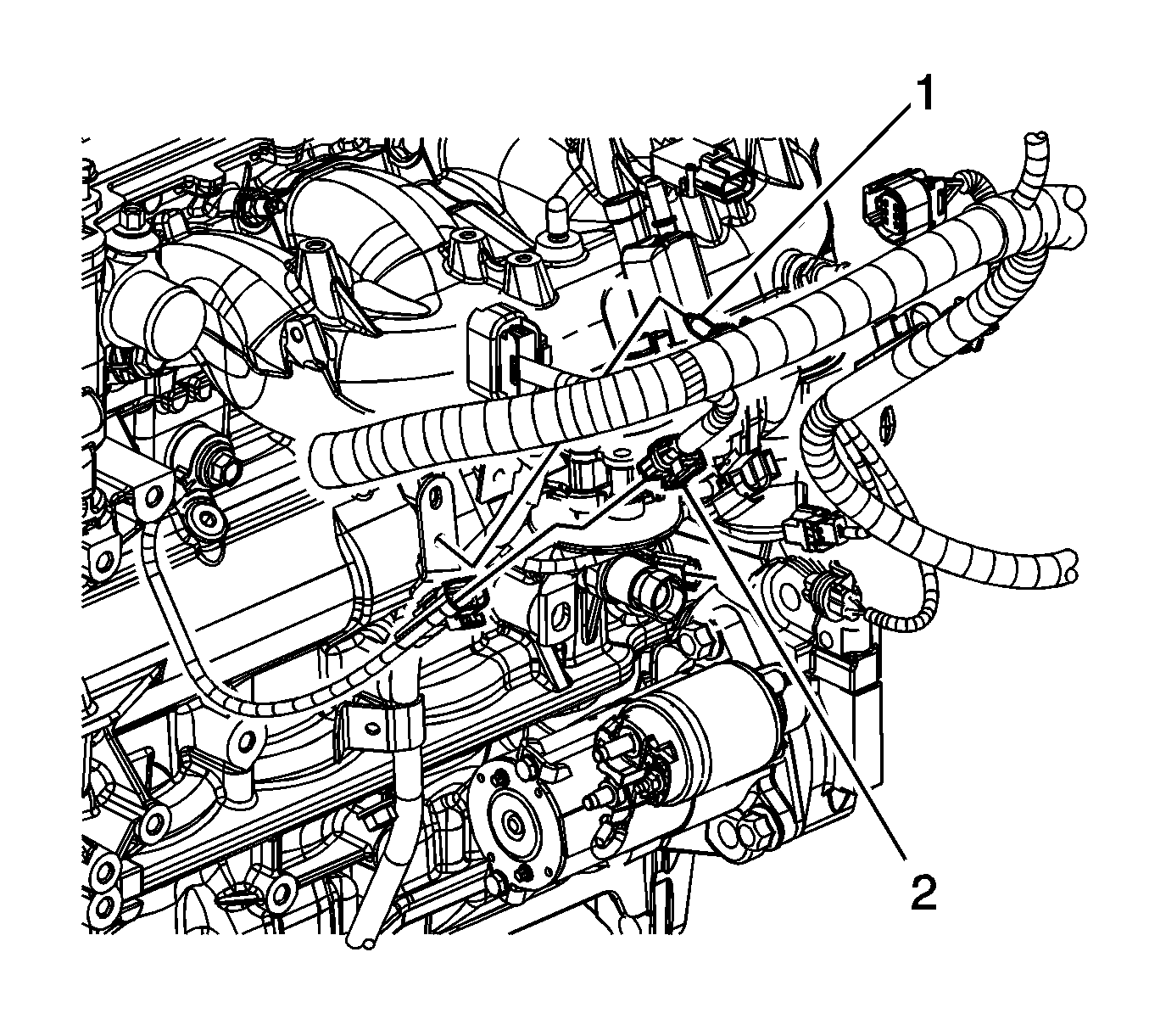
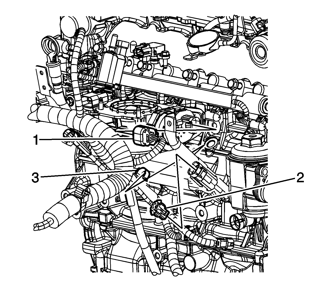
- Disconnect the engine wiring harness electrical connector (2) from the front knock sensor, if required.
- Disconnect the engine wiring harness electrical connector (2) from the rear knock sensor, if required.
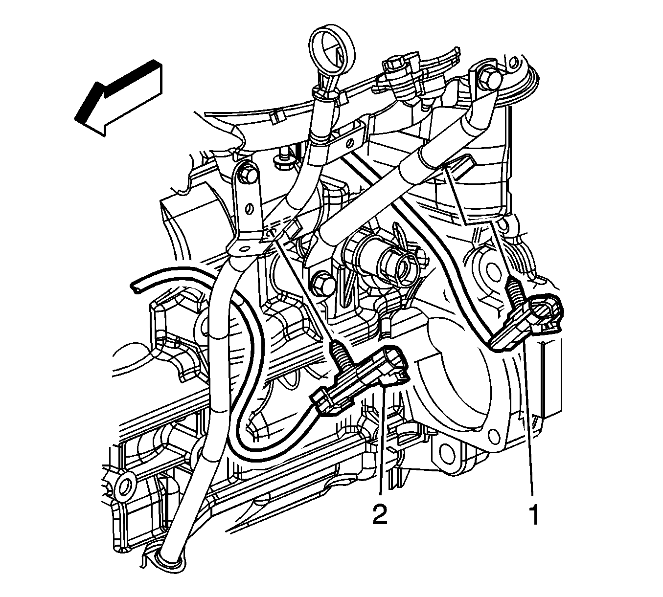
- Remove the front knock sensor clip (1) from the oil level indicator tube, if required.
- Remove the rear knock sensor clip (2) from the intake manifold brace, if required.
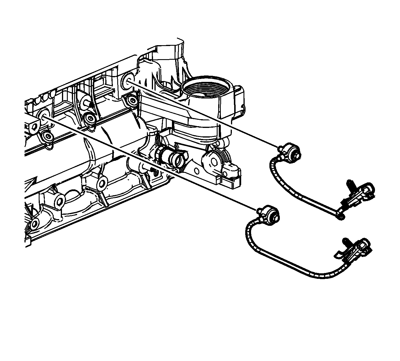
- Loosen the appropriate knock bolt.
- Remove the appropriate knock sensor.


Installation Procedure
Important: Rotate the pigtail 90 degrees from vertical before securing the fastener.
- Position the appropriate knock sensor to the engine block.
- Tighten the appropriate knock bolt.
- Install the front knock sensor clip (1) to the oil level indicator tube, if required.
- Install the rear knock sensor clip (2) to the intake manifold brace, if required.
- Connect the engine wiring harness electrical connector (2) to the rear knock sensor.
- Connect the engine wiring harness electrical connector (2) to the front knock sensor.

Notice: Refer to Fastener Notice in the Preface section.
Tighten
Tighten the bolt to 25 N·m (18 lb ft).


