For 1990-2009 cars only
Propeller Shaft Replacement Automatic
Removal Procedure
- Raise and support the vehicle. Refer to Lifting and Jacking the Vehicle.
- Remove the exhaust pipe and muffler. Refer to Muffler Replacement.
- Remove the floor panel rear panel. Refer to Floor Panel Tunnel Panel Replacement - Rear.
- Support the rear differential assembly with a suitable jack stand.
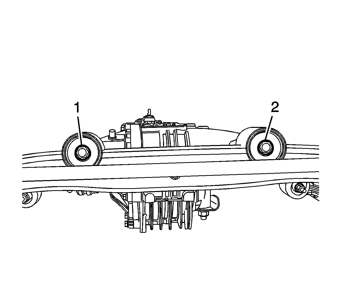
- Remove the left (1) and right (2) rear differential support bolts.
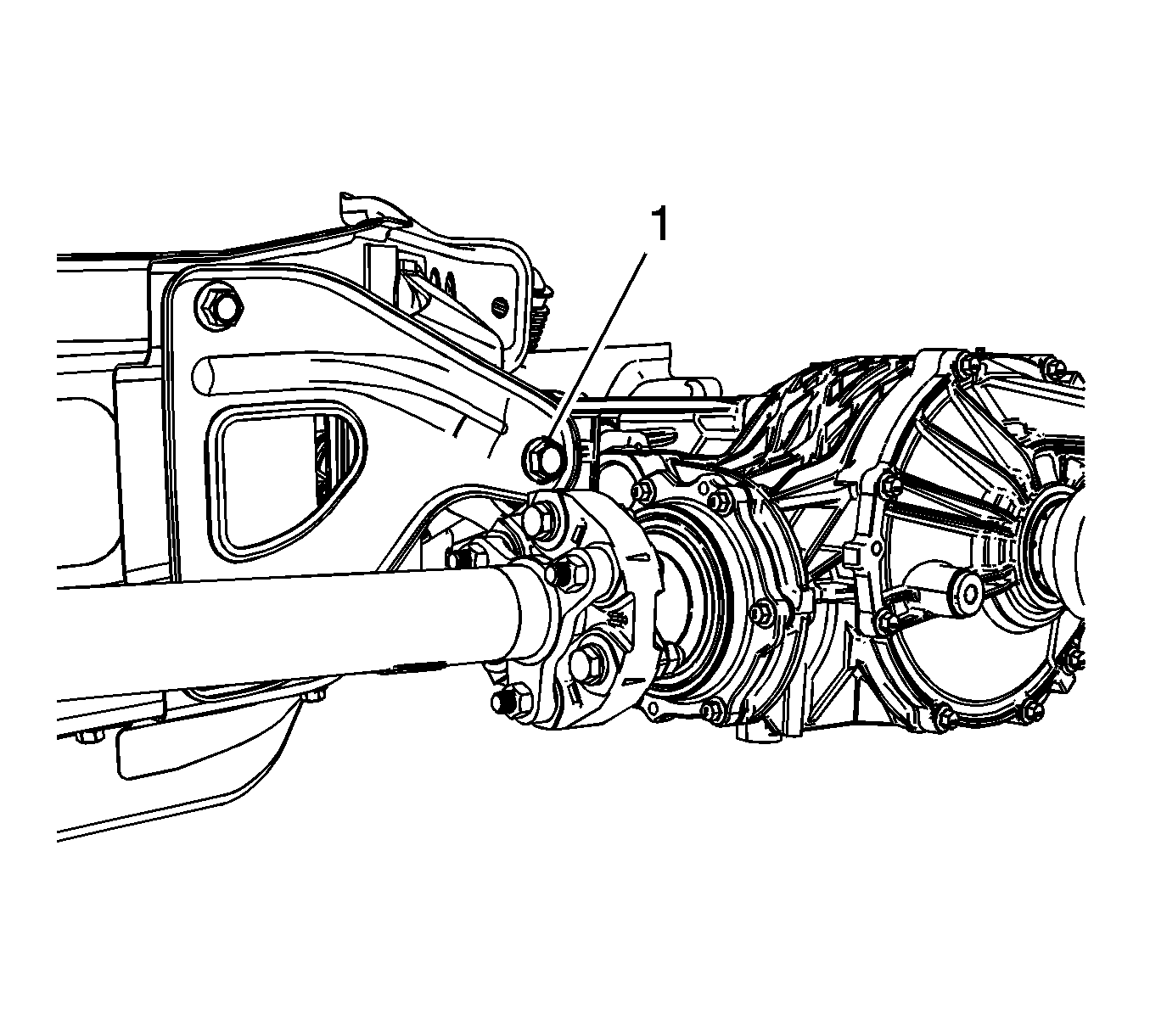
- Remove the front differential support bolt (1).
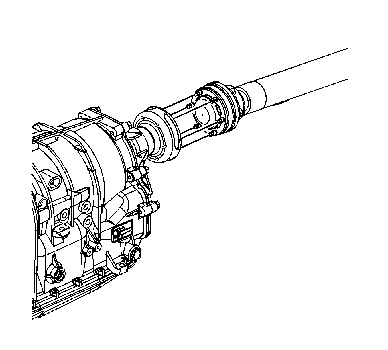
- Remove the propeller shaft bolts from the transmission output flange.
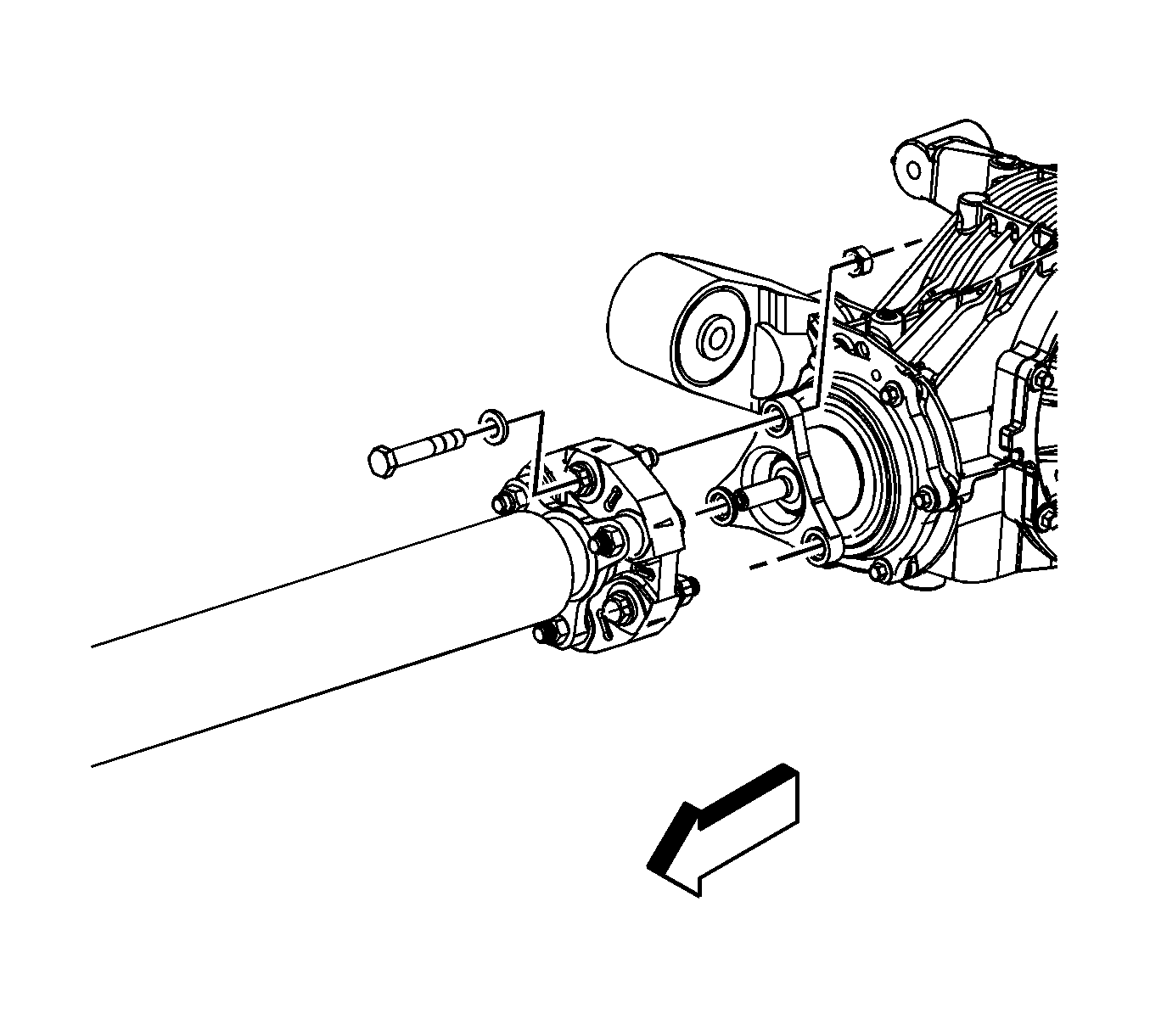
- Remove the propeller shaft nut and bolts from the differential drive flange.
- Lower the rear differential assembly enough to remove the propeller shaft from the vehicle.
Installation Procedure
- Remove all debris from the pilot shaft.
- Apply a small amount of chassis lube on the pilot shaft and pilot shaft hole in the propeller shaft.
- Position the propeller shaft on the transmission output flange.
- Raise the rear differential at the same time as aligning the propeller shaft pilot shaft and the propeller shaft pilot hole.
- Hand tighten the propeller shaft bolts to the transmission output shaft flange.
- Hand tighten the nuts and bolts to the rear differential drive flange.
- Position the rear differential assembly in the support.
- Install the left (1) and right (2) rear differential support bolts and tighten to 175 N·m (129 lb ft).
- Install the front differential support bolt (1) and tighten to 175 N·m (129 lb ft).
- Remove the jack stand from the rear differential assembly.
- Tighten the front propeller shaft bolts in sequence 1-6 to 40 N·m (30 lb ft).
- Tighten the rear propeller shaft bolts and tighten to 85 N·m (63 lb ft).
- Install the floor panel rear panel. Refer to Floor Panel Tunnel Panel Replacement - Rear.
- Install the exhaust pipe and muffler. Refer to Muffler Replacement.
- Remove the support and lower the vehicle.

Note: DO NOT tighten the propeller shaft front or rear fasteners until the front and rear differential support bolts are tighten to specifications.

Caution: Refer to Fastener Caution in the Preface section.


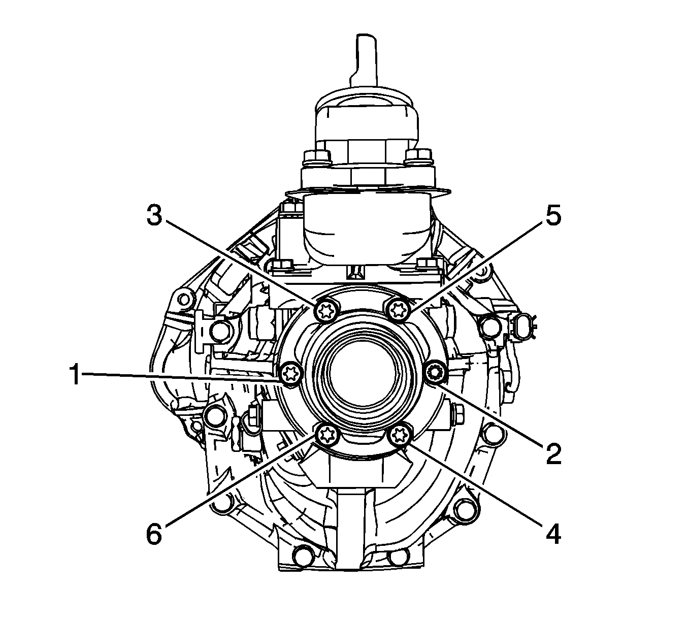

Propeller Shaft Replacement RPO ZOK
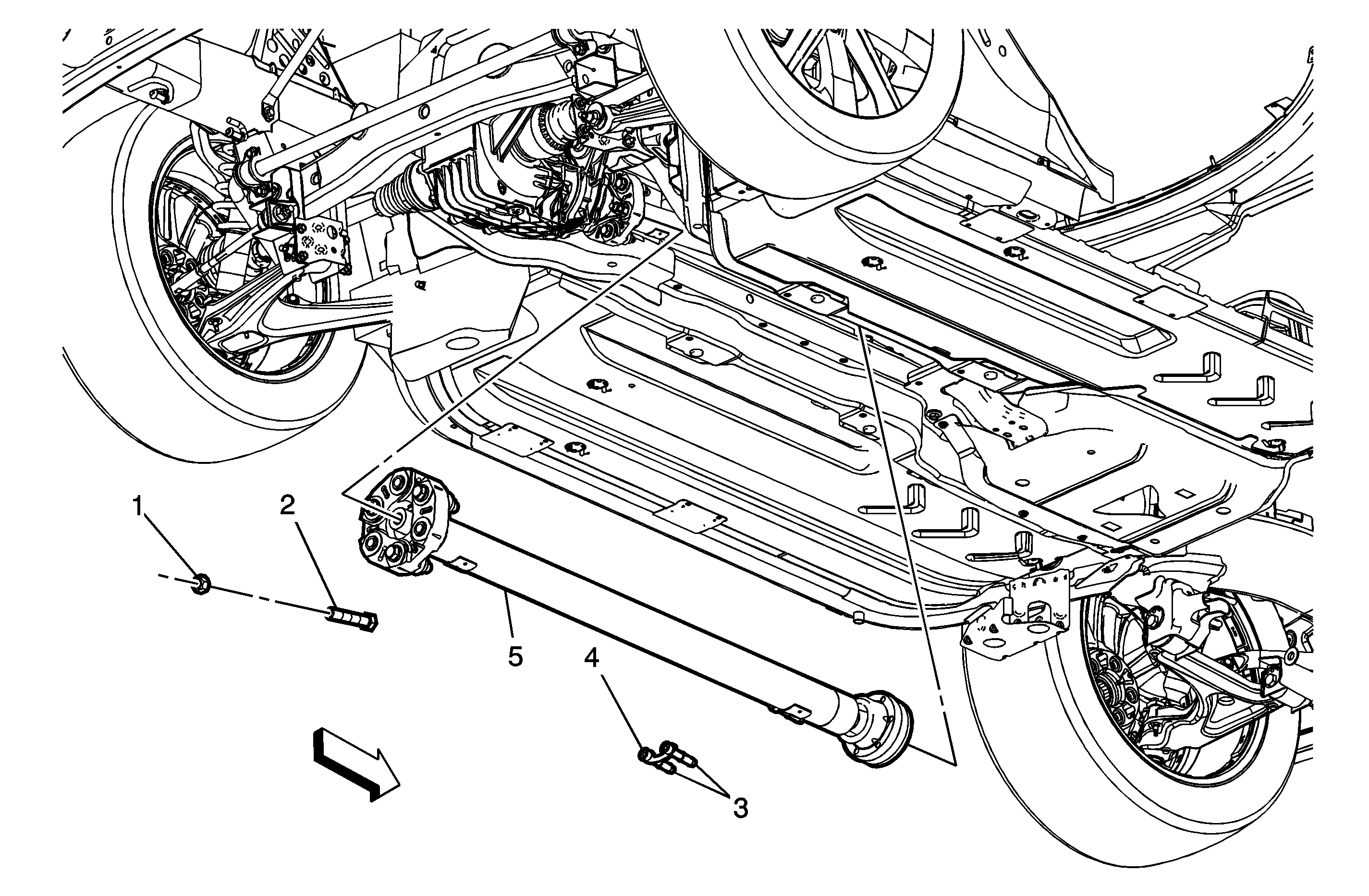
Callout | Component Name | ||||
|---|---|---|---|---|---|
Preliminary Procedures
| |||||
1 | Propeller Shaft Coupling Nut (Qty: 3) Caution: Refer to Fastener Caution in the Preface section. Tip
Tighten | ||||
2 | Propeller Shaft Coupler Bolt (Qty: 3) | ||||
3 | CV Joint Mounting Bolt (Qty: 6) Tip
Tighten | ||||
4 | CV Joint Mounting Bolt Spacer | ||||
5 | Propeller Shaft Tip
| ||||
