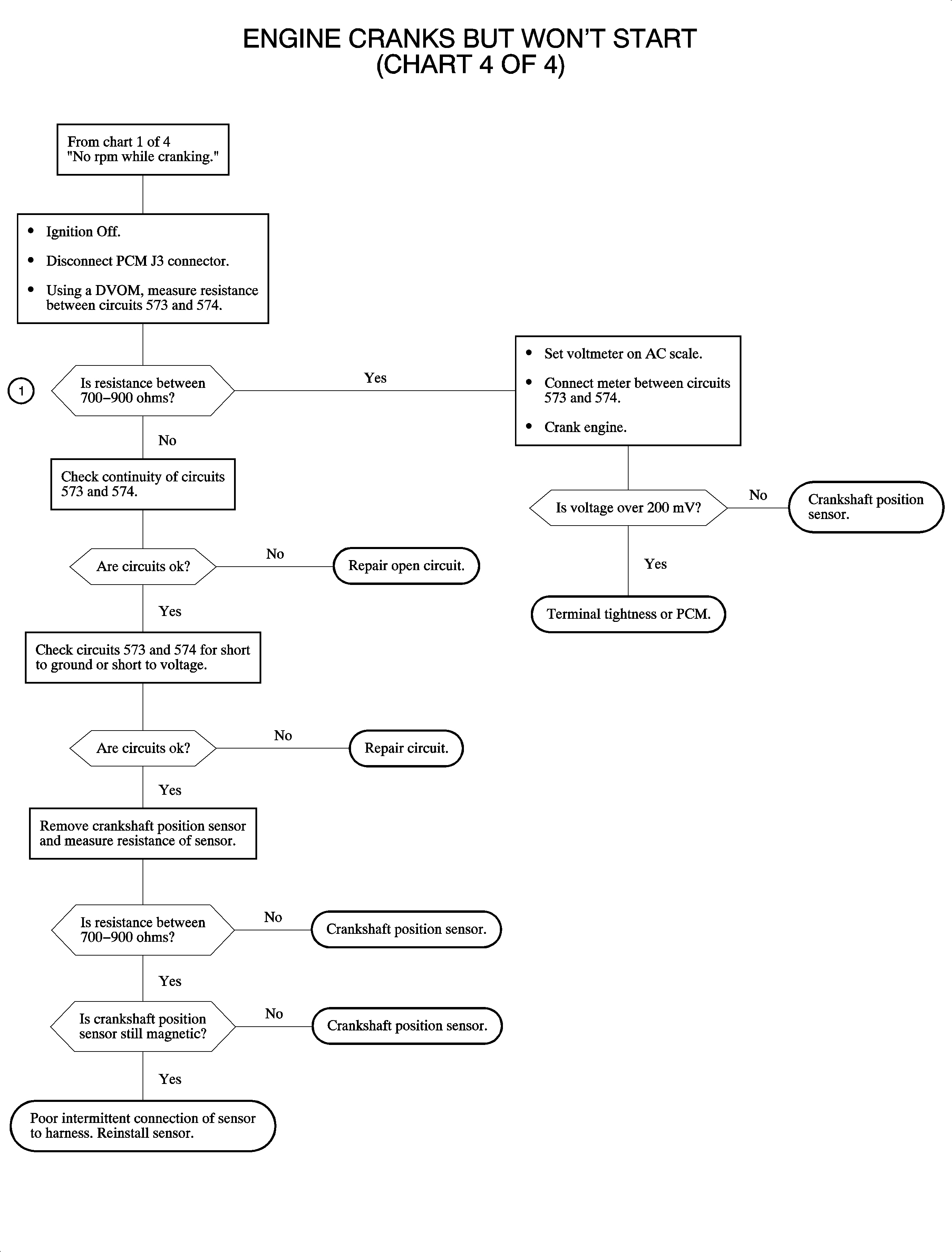
Engine Cranks But Does Not Run Chart 1 of 4
Circuit Description
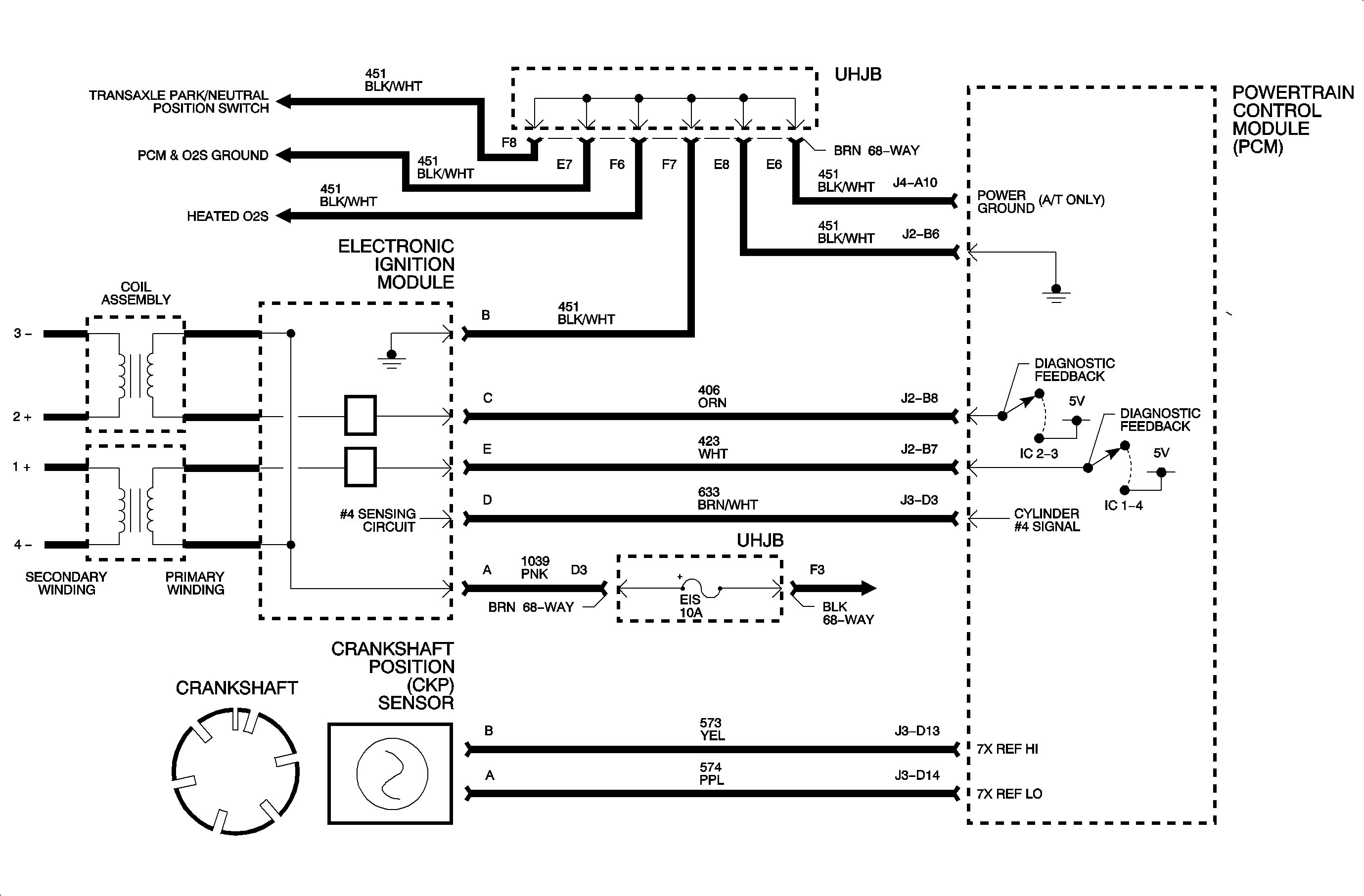
In order to diagnose this system, battery voltage must be above 11 volts. Cranking speed of the starter must be normal and fuel quality and quantity should be checked. When the ignition is ON and crank pulses are received, IC pulses are delivered to the EI module. Also, pulses are delivered to the injectors when crank pulses are received.
Diagnostic Aids
Water in the fuel causes a no start during cold weather starts.
An ECT sensor reading incorrectly can cause a no start or a hard start. This may be due to over-fueling or under-fueling.
ECT may be compared to IAT temperature with the scan tool if the engine has cooled overnight at ambient temperature. They should be within 4 degrees of each other with the ignition ON and the key OFF.
If the MAP sensor 5 volt line is shorted to ground, a DTC 1635 will set. Diagnose this DTC first.
Test Descriptions
- If an injector fuse is blown, all 4 injector DTCs will set when the ignition is turned ON.
- If the 5 volt reference circuit becomes shorted to ground it will result in a no start.
- An IC fault will cause 2 mating cylinders to not spark and may result in a no start, especially if the engine is cold.
- An EGR stuck open may result in a no start.
- If no RPM is indicated, spark and injectors will not be turned ON. The is no 7x signal to the PCM from the CKP sensor.
- Under normal cranking conditions, the 7x counter should count up to 14, 2 cranking revolutions, and reset to 0 when a cylinder #4 signal is received.
- Check for a flooded engine, or fouled plugs.
Important: Always check fuses first in the IPJB and the UHJB.
If the MAP sensor 5 volt line is shorted to ground, a DTC P1635 will set. Diagnose this DTC first.
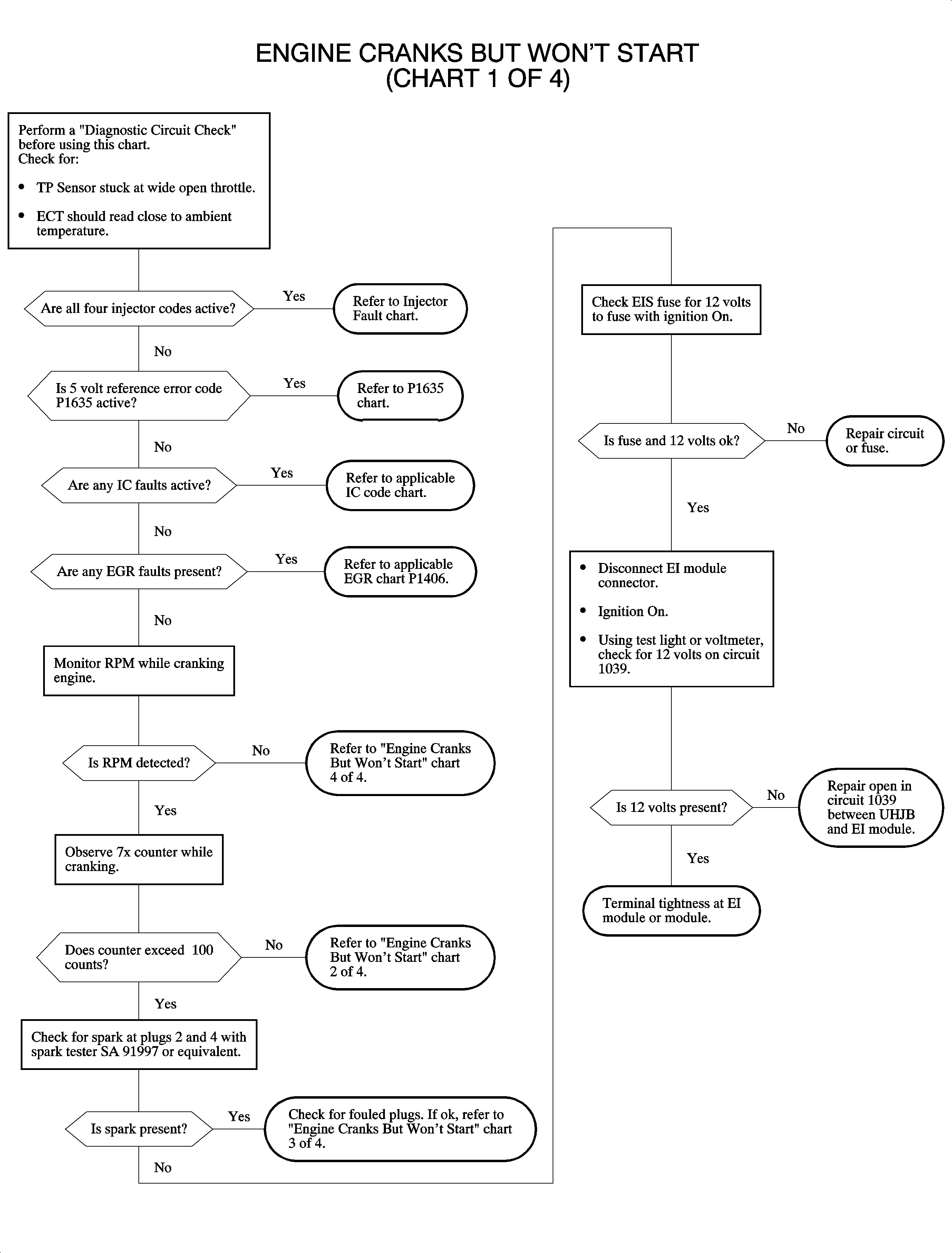
Engine Cranks But Does Not Run Chart 2 of 4
Circuit Description

This chart will isolate possible faults that could occur with the ignition system. Whenever the engine is cranking, as indicated by the sensor pulses, the PCM will send pulses to the EI module. The PCM pulses, 0-5 volts, to control the charge time and spark timing for each ignition event. Each pair, 1 and 4 or 2 and 3, of cylinders are controlled separately. An engine may or may not start on 2 cylinders.
Test Descriptions
- Since each coil is controlled separately, it is important to test for spark from each coil. If spark is available on both cylinders 2 and 4, it indicates the ignition system is OK. The fuel system should be checked at this point. Also the spark plugs could be fouled.
- Spark on one wire indicates that power and ground are OK to the module.
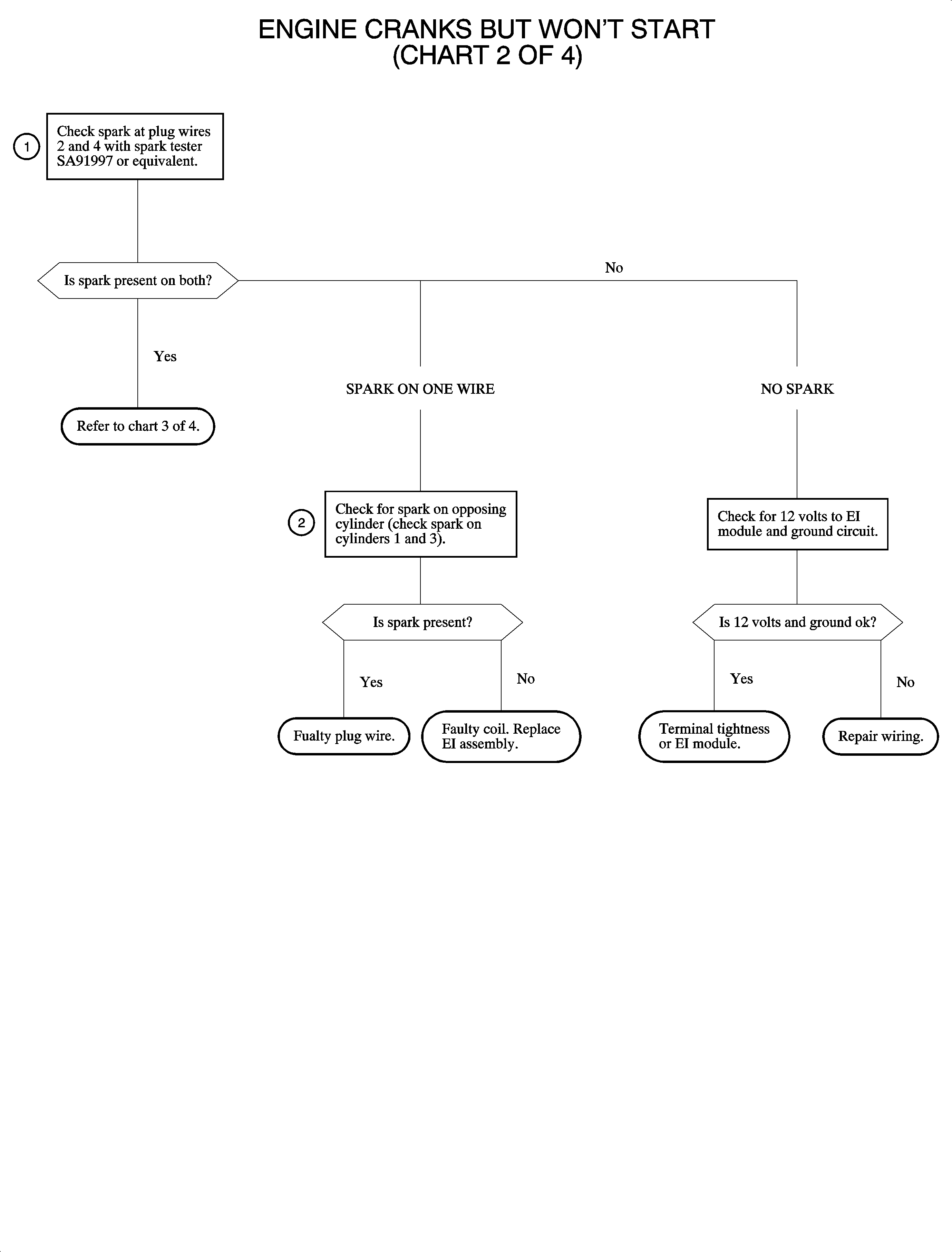
Engine Cranks But Does Not Run Chart 3 of 4
Circuit Description
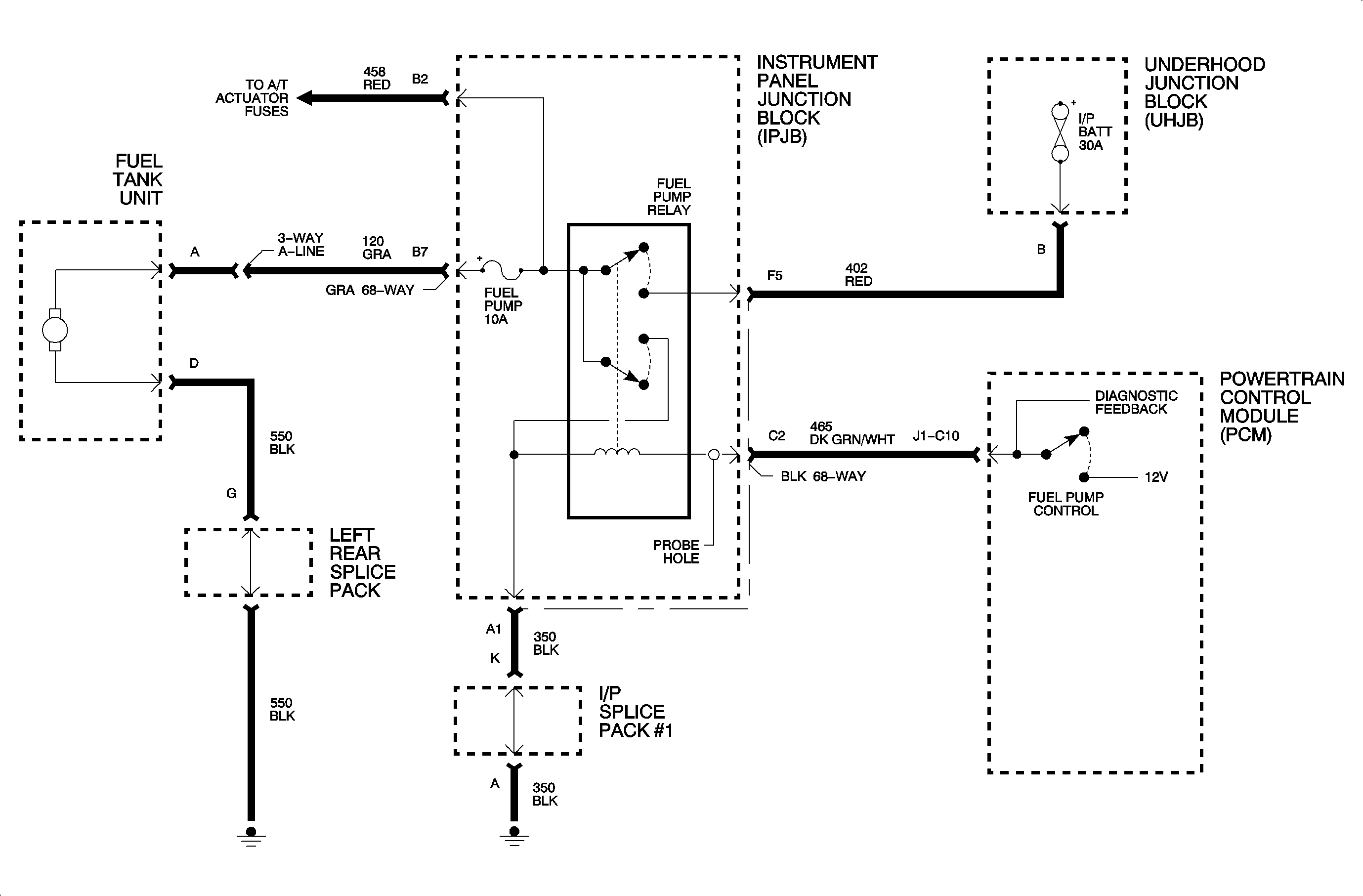
At this point in diagnosing a no start condition, it has been determined that the PCM inputs and the ignition system are OK. This chart will diagnose the fuel delivery system.
Test Description
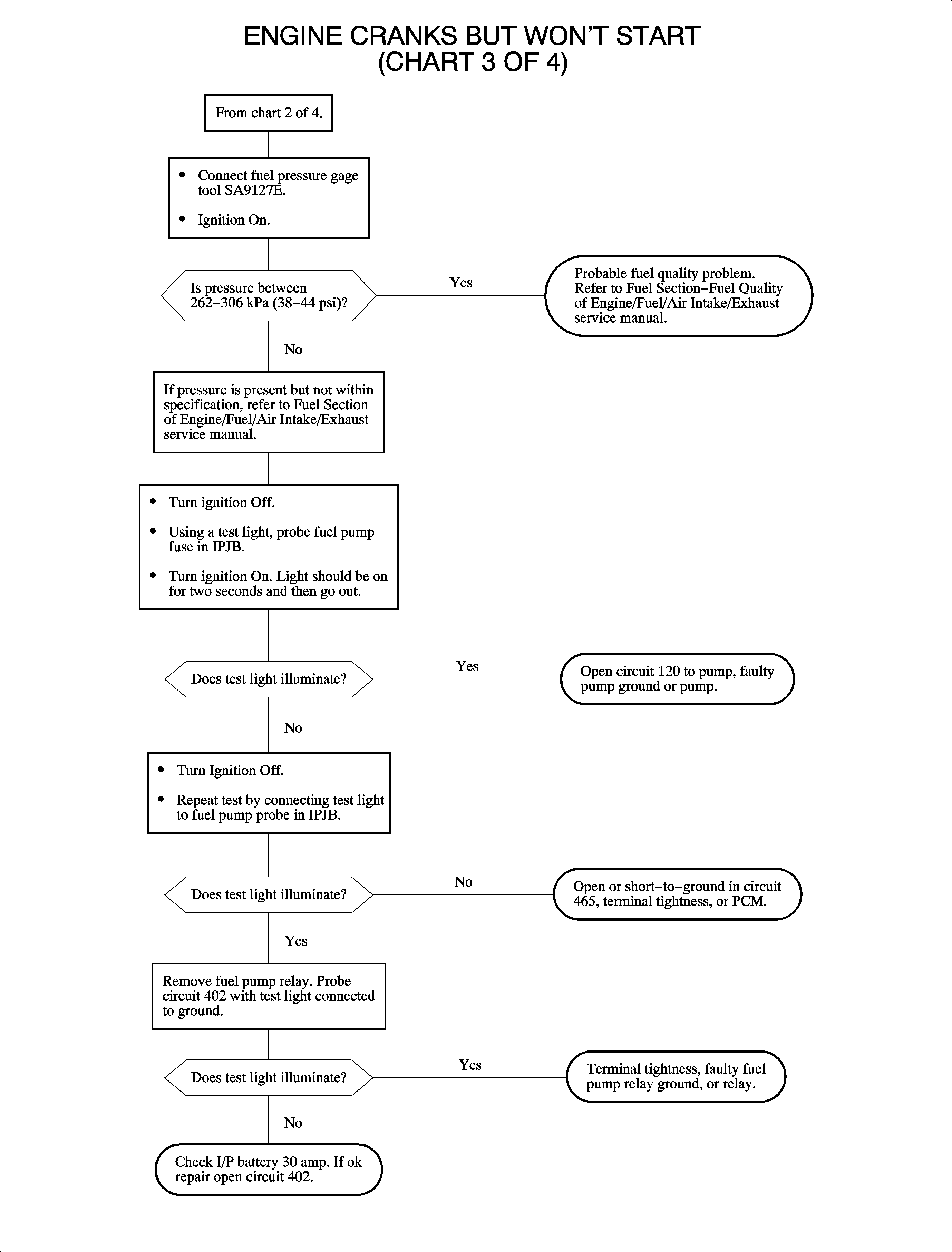
- When the ignition is turned ON, the fuel pump relay should be energized for about 2 seconds. After connecting a fuel pressure gage, the ignition may have to be cycled a few times before reaching the specified pressure. A scan tool can also be used to prime the fuel system. If pressure is available but low, it indicates the PCM and fuel pump relay circuit is OK.
- The ignition must be OFF for about 10 seconds before the fuel pump relay will be re-energized. If the test light illuminates at the fuel pump fuse, the PCM control and relay are OK.
- The PCM sends 12 volts to the relay coil.
Engine Cranks But Does Not Run Chart 4 of 4
Circuit Description

In order to control spark and fuel, the PCM must receive pulses from the crankshaft position sensor. The scan tool should always display RPM whenever the engine is running or cranking above 60 RPM. This chart will isolate the cause of crank pulses not being received by the PCM.
Diagnostic Aids
An intermittent in the crankshaft position sensor circuit may cause DTC P1599 engine stall DTC to set.
Test Description
The correct resistance of the crankshaft position sensor does not indicate the sensor is OK. The output voltage of the sensor must also be checked. If resistance is greater than 900 ohms, check for high resistance, corrosion, or open circuits. If resistance is less than 700 ohms, check for a short to ground or for circuits 573 and 574 shorted together.
