Energizing the Fuel Pump
All of the fuel system tests will require operation of the fuel pump to measure pressure, evaluate pressure decay, or perform the pressure at calibrated flow tests.
Although the fuel pump can be controlled with the ignition, this is fairly awkward for the following reasons:
| • | The pump is only energized for 2-3 seconds at Key ON. Then a wait of 10 seconds is required after Key OFF before the pump can be powered again. |
| • | Some of the tests are run with the vehicle on the hoist with control of the pump under the car required. |
| • | The pressure at flow tests require the pump to run for 10-20 seconds. |
Important: Once the fuel pump is commanded ON with the scan tool, it will be energized for 1 minute before it times out and returns to the OFF status. Do not leave the vehicle unattended while running any of the system tests with the pump ON.
The scan tool provides control of the fuel pump at the technician's finger-tips. The tool will run the pump for 1 minute after the ON command. This timer will then shut the pump OFF.
Fuel System Testing
The fuel system tests outlined in the fuel system diagnostic flow chart and detailed procedures, Tests 1-9, provide a systematic approach to determining whether the fuel system, from fuel pump to the fuel injectors, is functioning as intended.
For the engine to operate as designed, the fuel supply system must do the following:
| • | Deliver fuel at the proper pressure |
| • | Deliver fuel with adequate volume |
| • | Maintain pressure after the engine, and fuel pump, are turned OFF |
In addition, the fuel injectors must deliver the precise quantity of fuel at exactly the correct intervals with no leakage of fuel when the injector is turned OFF.
The battery of tests outlined in the Fuel Supply Diagnosis flow chart are designed to evaluate all the performance characteristics. Symptoms or complaints related to the fuel system include:
| • | Hard starting |
| • | No start (Hot and/or cold) |
| • | Extended cranking |
| • | No/low power |
| • | Start/stall |
| • | Rough idle |
| • | Poor acceleration, stalling, stumbling |
| • | Misfire/backfire |
| • | Rough/erratic idle |
| • | Surges/hesitates |
Diagnostic trouble codes associated with fuel supply problems include DTC P0171 and P0172.
Important: The performance of the fuel pump (pressure and flow) is very dependent on supply voltage. The voltage must be above 12 volts when running any of the diagnostic tests. Published test specifications cover the range of system operation from 12-14 volts, but are biased towards the lower voltages (12-12.7 volts) since all tests are run with the engine OFF. All accessory loads should be off when running any tests (DRLs, interior lights, radio, etc.) to provide maximum available voltage for the tests. If voltage is below 12 volts, the battery must be charged before running tests.
Test 1: Fuel Pump Operational Test -- Test to establish whether fuel pump is operating and providing fuel to the injectors.Test 2: Fuel System Pressure Test, at idle or engine OFF -- Tests the basic integrity of the fuel system to determine whether regulated operating pressure is achieved under low load conditions.
Test 3 and 4: Fuel Pump Flow/Pressure Tests -- Tests to determine if the fuel pressure is within operating limits while simulating the flow demand of the engine running at wide open throttle. These tests are run with the engine OFF and provide a means, based on testing at 2 points in the system, of determining if the fuel filter/pressure regulator and fuel pump are operating to design specifications. The testing is performed using the SA9127E-7 Fuel Flow/Pressure Adapter which incorporates a precision orifice to meter 50 liters/hr (13 gallons/hr) at a delivery pressure of 330 kPa (48 psi).
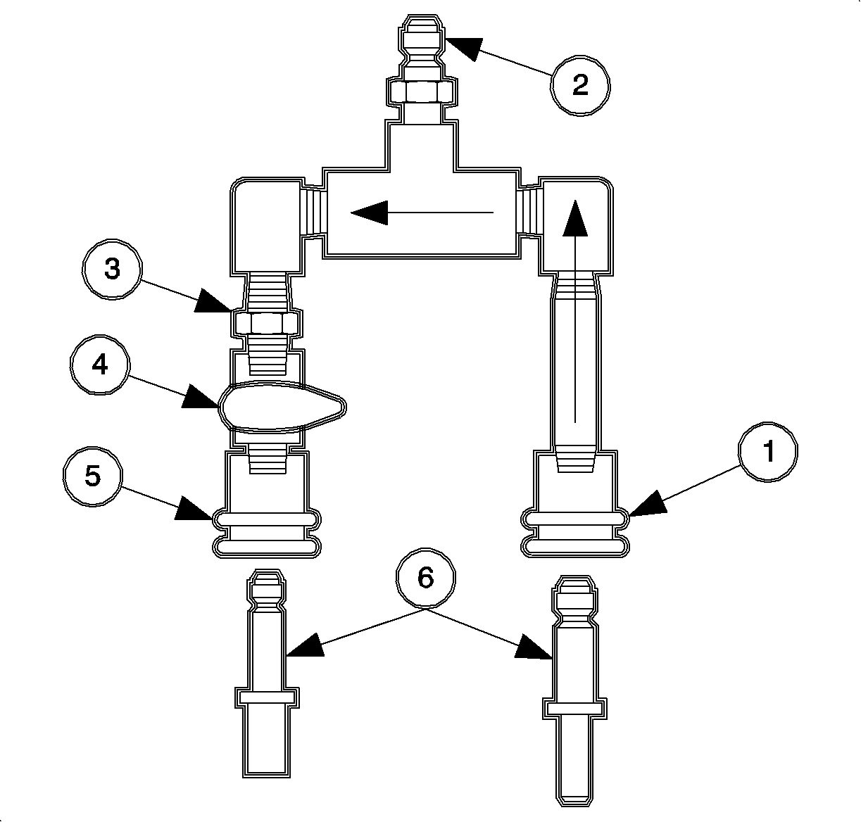
The flow/pressure adapter consists of the following:
| • | Female, quick connect inlet fitting (1) |
| • | Male, quick connect fitting (2) |
| • | Precision orificed fitting (3) |
| • | ON/OFF flow control valve (4) |
| • | Female, quick connect outlet fitting (5) |
| • | Adapter fittings - male 3/8 inch and 5/16 inch quick-connects for fuel lines to 1/4" quick-connects on test adapter (6) |
It is connected with the inlet side (1) to the fuel feed, either at the fuel rail or at the filter/pressure regulator inlet, the outlet (5) to fuel return (or drain), and the gage port (2) to the pressure gage. The ON/OFF control valve (4) provides a means to control fuel flow for pressure and leakdown testing.
The test criteria is the fuel pressure read while the fuel pump is energized with the engine OFF. Refer to Energizing the Fuel Pump. If the pressure measured is within specification, then the fuel supply is capable of meeting all volume requirements of the engine.
Tests 5, 6, and 7: Fuel System Pressure Leakdown, Decay - These tests determine if the fuel system will maintain pressure after the engine, and fuel pump, are shut OFF. Fuel pressure must be maintained after shut OFF to ensure quick restarts and prevent fuel vapor from forming at the fuel rail, causing hard or extended cranks. The tests are arranged to allow isolation of the problem components or area by evaluating components in sequence.Test 8: Fuel Injectors Tip Leakage Test - This test determines if the fuel injectors are leaking fuel into the intake system. Leaking fuel injectors can cause problems with extended cranks, hard starting, and rich running conditions, DTC P0172.
Test 9: Fuel Injector Balance Test - This test determines if the fuel injectors are metering an equal quantity of fuel when they are commanded open. By measuring the fuel pressure drop during a timed cycle of opening each injector, a relative evaluation of each injector's flow rate is made. This test is designed to identify injectors with significant differences in flow rate but will not identify problems with an injector flow pattern, i.e., improperly sized spray cone, non-uniform spray cone pattern, mis-directed spray cone, etc.
1 - Fuel Pump Operational Test
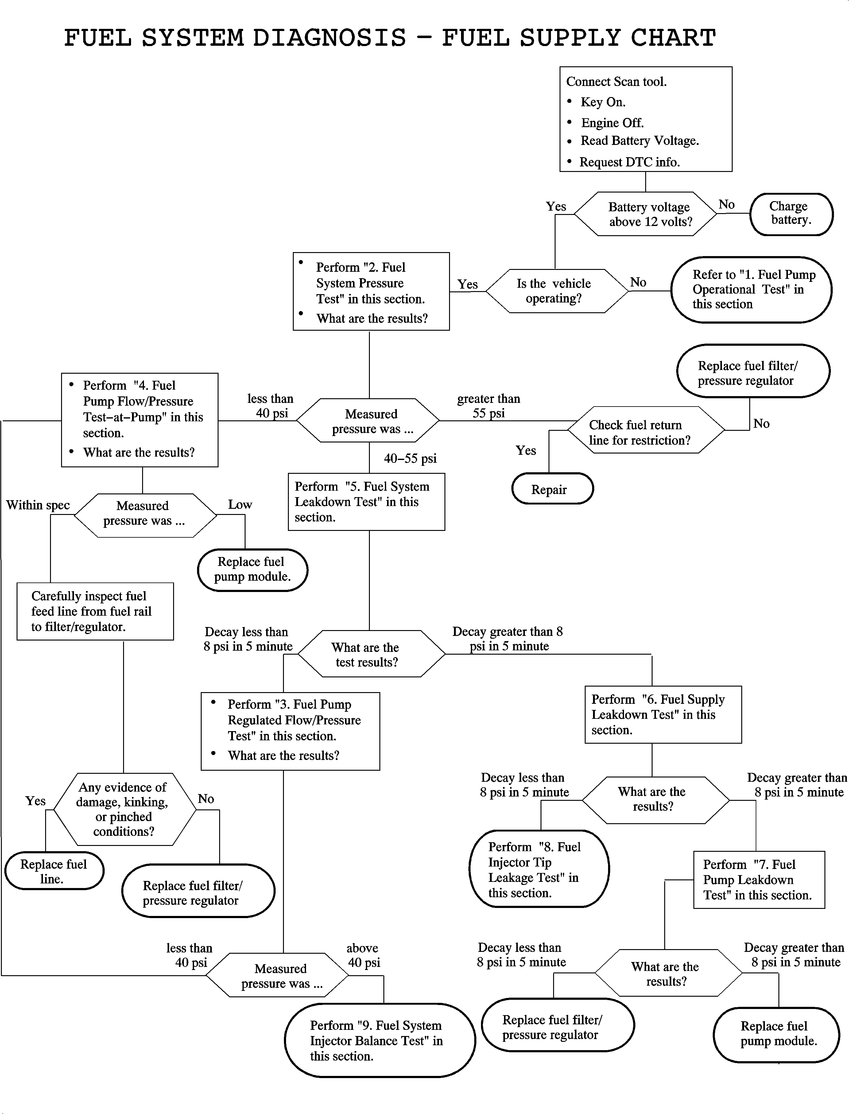
If the vehicle is not operating or will not start or run, then a determination must be made if the fuel pump is working and fuel under pressure is being delivered to the fuel rail.
- Remove the cap on the fuel pressure test port at the fuel rail and slightly depress the tip of the schrader valve. Note whether fuel is present.
- If fuel, under pressure, is present proceed to test 2 - FUEL SYSTEM PRESSURE TEST.
- If no fuel is present, assure that there is fuel in the tank. Check fuel gage.
- Evaluate the fuel pump electrical circuit.
Caution: Do not allow smoking or the use of open flames in the area where work on the fuel or EVAP system is taking place. Anytime work is being done on the fuel system, disconnect the negative battery cable, except for those tests where battery voltage is required.
Caution: Whenever fuel line fittings are loosened or removed, wrap a shop cloth around the fitting and have an approved container available to collect any fuel.
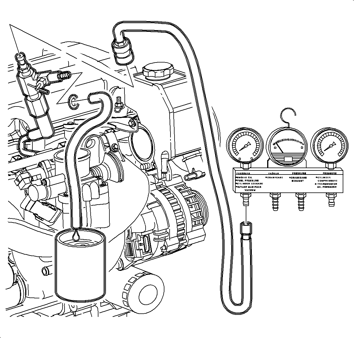
2 - Fuel System Pressure Test
This test will determine whether there is adequate fuel pressure delivered to the fuel injectors to start and run the engine under low load conditions.
- Remove the air induction tube.
- Relieve the fuel system pressure.
- Connect the SA9127E Gage Bar Set and pressure gage to fuel pressure test port.
- Energize the fuel pump for a minimum of 10 seconds. Refer to Energizing the Fuel Pump.
- Compare the pressure recorded to the published specification.
- Return to Fuel System Diagnosis - Fuel Supply Chart and use the test result to make the appropriate decision.
Caution: Do not allow smoking or the use of open flames in the area where work on the fuel or EVAP system is taking place. Anytime work is being done on the fuel system, disconnect the negative battery cable, except for those tests where battery voltage is required.
Important: Battery must be at a minimum of 12 volts when performing any fuel system test. Charge battery before proceeding if below 12 volts.
| 4.1. | Close the valve on the fuel gage pressure adapter. |
| 4.2. | Energize the fuel pump. |
| 4.3. | Record the fuel pressure, while the fuel pump is energized. |
| 4.4. | Relieve the fuel pressure. |
| 4.5. | Repeat this procedure a minimum of 2 times. |
Fuel System Pressure, Battery Voltage - Minimum 12 Volts
| • | Minimum - 40 psi (276 kPa) |
| • | Maximum - 55 psi (379 kPa) |
Fuel Pump Flow/Pressure Tests
These tests will determine whether the fuel system can supply adequate volume of fuel at the desired pressure to operate the engine under full load conditions. The test is done at 2 points in the system, fuel rail and fuel pump, to isolate and identify the problem component: fuel pump, filter pressure regulator, or fuel supply line.
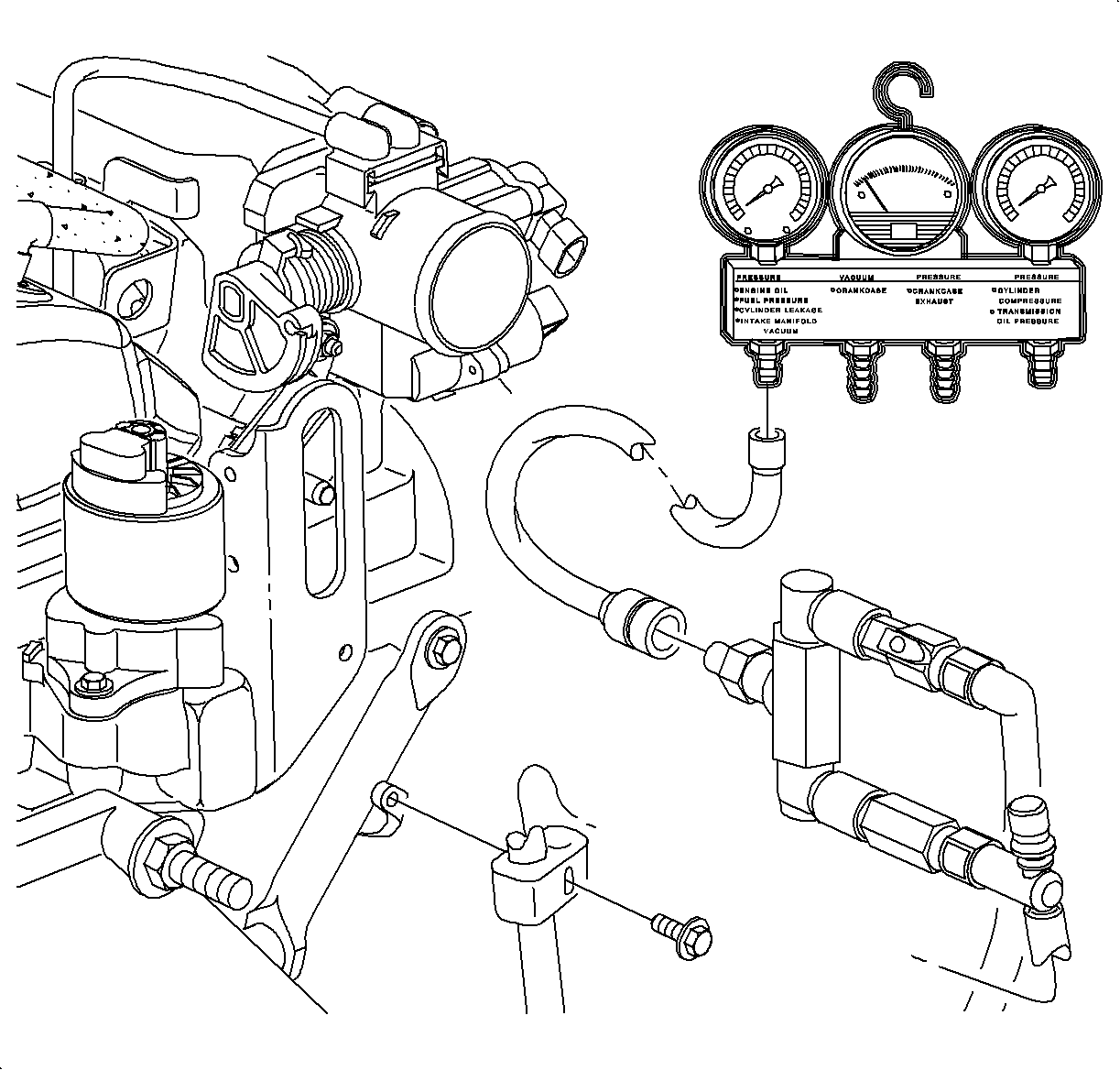
3 - Fuel Pump Regulated Flow/Pressure Test
- Remove the air induction tube.
- Relieve the fuel system pressure.
- Remove the fuel feed line retainer clip attachment screw , 10 mm hex.
- Disconnect the fuel feed line at the fuel rail.
- Connect the INLET side of the SA9127E-7 Fuel Flow/Pressure Test Adapter into fuel feed line 90 degree quick connect and make sure the fitting is firmly latched.
- Connect the fuel pressure gage to the test adapter.
- Connect a fuel return hose to the quick connect on the test adapter and place the other end of the line into an approved container or run a return hose back to the fuel filler pipe.
- Turn the ON/OFF valve on the test adapter to ON.
- Energize the fuel pump for a minimum of 10 seconds. Refer to Energizing the Fuel Pump.
- Compare the pressure recorded to the published specification.
- Refer to Fuel System Diagnosis - Fuel Supply Chart and use the test result to make the appropriate decision.
Caution: Do not allow smoking or the use of open flames in the area where work on the fuel or EVAP system is taking place. Anytime work is being done on the fuel system, disconnect the negative battery cable, except for those tests where battery voltage is required.
Important: Battery must be at a minimum of 12 volts when performing any fuel system test. Charge the battery before proceeding if below 12 volts.

Caution: Whenever fuel line fittings are loosened or removed, wrap a shop cloth around the fitting and have an approved container available to collect any fuel.
Notice: To properly utilize the fuel flow/pressure test adapter, it must always be connected with the fuel feed line on the INLET. The inlet side is the side of the adapter and the fuel return or drain line connected to the side with the flow control (ON/OFF) valve. If not connected properly, a zero pressure reading will always be read. Use the appropriately sized connector fittings to hook up the adapter to the feed and return lines.
The Regulated Fuel Pressure Under Flow at Fuel Rail is a Minimum 276 kPa (40 psi).
Important: The battery must be at a minimum of 12 volts when performing any fuel system test.
| 9.1. | Record the fuel pressure, while the fuel pump is energized. |
| 9.2. | Repeat this procedure a minimum of 2 times. |
4 - Fuel Pump Flow/Pressure Test
For this test, the vehicle will be raised on the hoist and a means of controlling the fuel pump from under the vehicle is required. The scan tool readily provides this function. Refer to Energizing the Fuel Pump.
- Connect the scan tool to the vehicle and turn the ignition to ON.
- Relieve the fuel system pressure.
- Raise the vehicle to a comfortable working position.
- Disconnect the fuel feed (5/16 in) and the fuel return (3/8 in) lines at the fuel filter/pressure regulator.
- Connect the SA9127E-7 Fuel Flow/Pressure Test Adapter to the (1) feed and (2) return lines and make sure the connections are firmly latched.
- Connect the fuel pressure gage to the test adapter.
- Turn the ON/OFF valve on the test adapter to ON.
- Energize the fuel pump for a minimum of 10 seconds.
- Using the scan tool, determine the battery voltage, with the pump OFF, and record.
- Compare the pressure and voltage recorded to the published specification.
- Use the test result to make the appropriate decision.

Caution: Do not allow smoking or the use of open flames in the area where work on the fuel or EVAP system is taking place. Anytime work is being done on the fuel system, disconnect the negative battery cable, except for those tests where battery voltage is required.
Important: The battery must be at a minimum of 12 volts when performing any fuel system test. Charge battery before proceeding if below 12 volts.
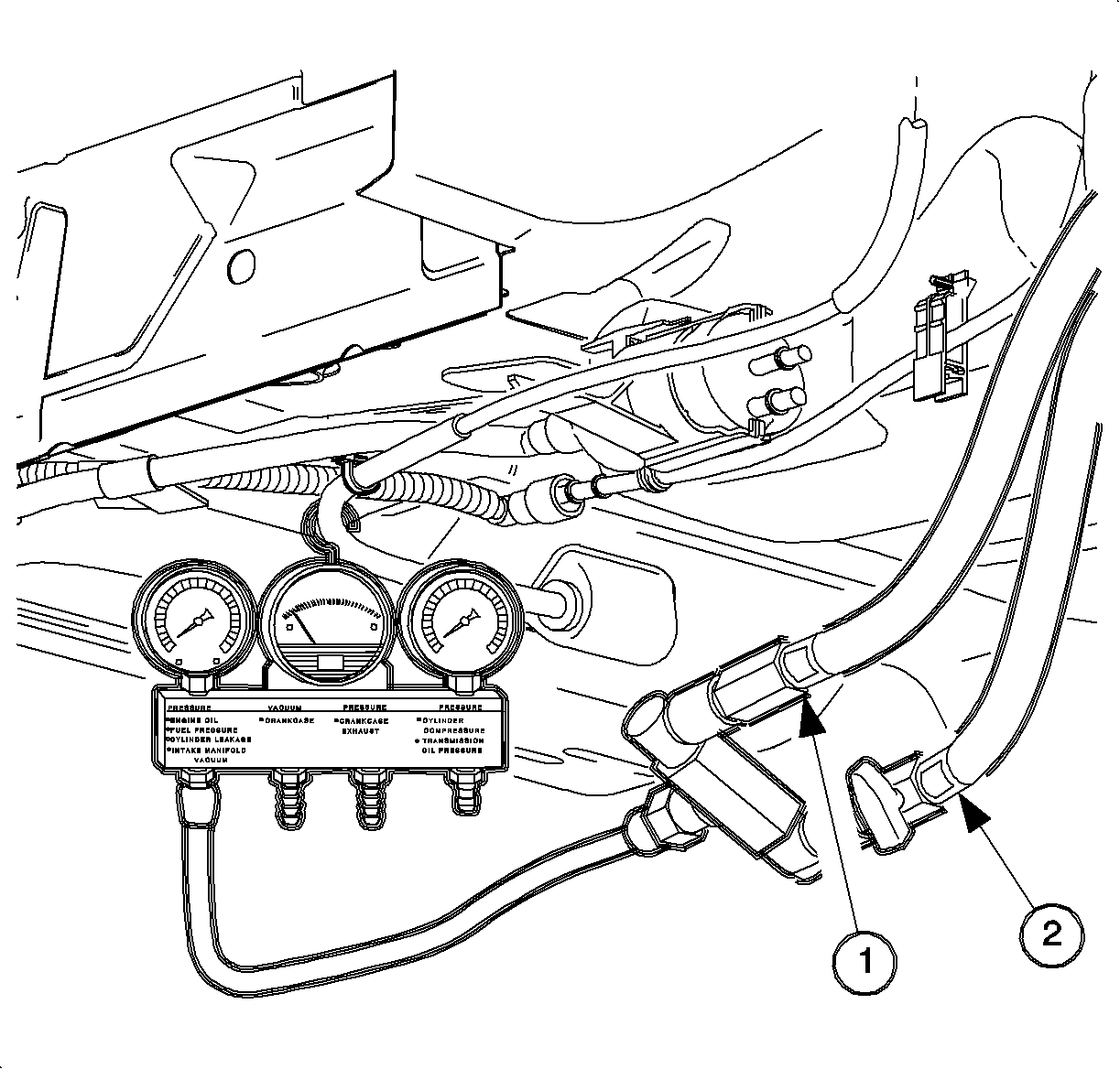
Caution: Whenever fuel line fittings are loosened or removed, wrap a shop cloth around the fitting and have an approved container available to collect any fuel.
Notice: To properly utilize the fuel flow/pressure test adapter, it must always be connected with the fuel feed line on the INLET. The inlet side is the side of the adapter and the fuel return or drain line connected to the side with the flow control (ON/OFF) valve. If not connected properly, a zero pressure reading will always be read. Use the appropriately sized connector fittings to hook up the adapter to the feed and return lines.
Fuel Pressure Under Flow at Fuel Rail
| • | 12-12.4 volts |
| • | Minimum 276 kPa (40 psi) |
| • | 12.4-12.8 volts |
| • | Minimum 276 kPa (44 psi) |
| 8.1. | Record the fuel pressure while the pump is energized |
| 8.2. | Repeat this procedure a minimum of 2 times. |
5 - Fuel System Leakdown Test
The fuel system leakdown test will determine if the fuel system is able to hold fuel pressure when the fuel pump is not operating. The system must hold pressure to assure that the fuel supply circuit, fuel lines, filter/regulator, and fuel rail, is full of fuel. When the fuel supply is completely charged, fuel will be available at the injectors as soon as the ignition is turned ON.
- Remove the air induction tube.
- Relieve the fuel system pressure.
- Connect the SA9127E Gage Bar Set to the fuel pressure port.
- Energize fuel pump for a minimum of 10 seconds. Refer to Energizing the Fuel Pump in this manual.
- Shut the fuel pump OFF and wait 5 minutes.
- Record the fuel pressure and subtract from the pressure recorded in Step 4.1.
- Compare the pressure loss, decay, to the published specification.
- Use the test result to make the appropriate decision.
Caution: Do not allow smoking or the use of open flames in the area where work on the fuel or EVAP system is taking place. Anytime work is being done on the fuel system, disconnect the negative battery cable, except for those tests where battery voltage is required.
Caution: Whenever fuel line fittings are loosened or removed, wrap a shop cloth around the fitting and have an approved container available to collect any fuel.
Important: The battery must be at a minimum of 12 volts when performing any fuel system test. Charge battery before proceeding if below 12 volts.
| 4.1. | Record the fuel pressure. |
| 4.2. | Repeat this procedure a minimum of 2 times. |
Fuel System Leakdown Test: The Maximum Pressure Decay after 5 minutes - 55 kPa (8 psi).
6 - Fuel Supply Leakdown Test
This test will determine if the fuel supply system, up to the fuel rail and injectors, will maintain pressure after the fuel pump is turned off.
- Remove the air induction tube.
- Relieve the fuel system pressure.
- Remove the fuel feed line retainer clip attachment screw, 10 mm hex.
- Disconnect the fuel feed line at the fuel rail.
- Connect the pressure gage to the test adapter.
- Energize the fuel pump for a minimum of 10 seconds. Refer to Energizing the Fuel Pump in this manual.
- Shut the fuel pump OFF and wait 5 minutes.
- Record the fuel pressure and subtract from the pressure recorded in step 6.
- Compare the pressure loss, decay, to the published specification.
- Use the test result to make the appropriate decision.

Caution: Do not allow smoking or the use of open flames in the area where work on the fuel or EVAP system is taking place. Anytime work is being done on the fuel system, disconnect the negative battery cable, except for those tests where battery voltage is required.
Important: This test can be performed using the J 37287-100 Fuel Line Shut Off Quick Connect Adapter.
Important: The battery must be at a minimum of 12 volts when performing any fuel system test. Charge battery before proceeding if below 12 volts.
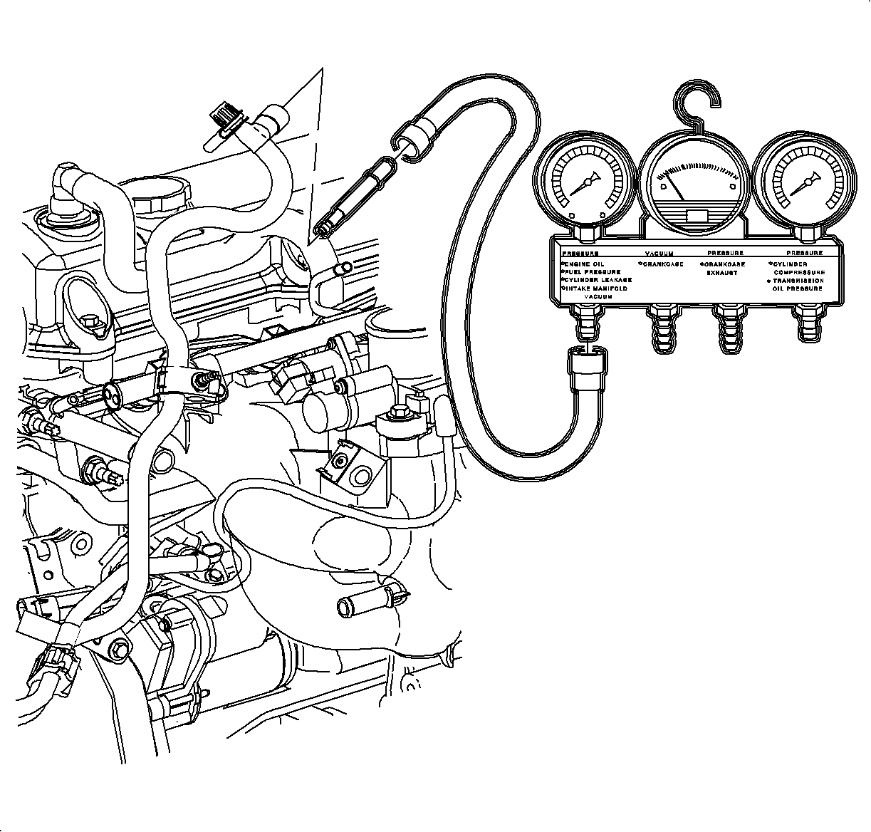
Caution: Whenever fuel line fittings are loosened or removed, wrap a shop cloth around the fitting and have an approved container available to collect any fuel.
| 4.1. | Connect the fuel feed line directly to the pressure gage using the J 37287-100 (3/8 in x 1/4 in). |
| Notice: To properly utilize the fuel flow/pressure test adapter, it must always be connected with the fuel feed line on the INLET. The inlet side is the side of the adapter and the fuel return or drain line connected to the side with the flow control (ON/OFF) valve. If not connected properly, a zero pressure reading will always be read. Use the appropriately sized connector fittings to hook up the adapter to the feed and return lines. |
| 4.2. | If using the fuel flow/pressure test adapter, connect the INLET to the fuel feed line and assure that the flow valve is OFF. |
Fuel System Leakdown Test: Maximum Pressure Decay after 5 minutes - 55 kPa (8 psi).
| 6.1. | Record the fuel pressure. |
| 6.2. | Repeat this procedure a minimum of 2 times. |
7 - Fuel Pump Leakdown Test
This test will determine if the fuel pump will maintain pressure after the pump is turned OFF.
For this test, the vehicle will be raised on the hoist and a means of controlling the fuel pump from under the vehicle is required. The scan tool readily provides this function. Refer to Energizing the Fuel Pump.
- Connect the scan tool to the vehicle and turn the ignition to ON.
- Relieve the fuel system pressure.
- Raise the vehicle to a comfortable working position.
- Disconnect the fuel feed (5/16 in) and fuel return (3/8 in) lines at the fuel filter/pressure regulator.
- Connect the SA9127E-7 Fuel Flow/Pressure Test Adapter to the (1) feed and (2) return lines and make sure the connections are firmly latched.
- Connect the fuel pressure gage to the test adapter.
- Turn the ON/OFF flow valve on the test adapter to ON.
- Energize the fuel pump.
- Shut the fuel pump OFF and wait 5 minutes.
- Record the fuel pressure and subtract from the pressure recorded in Step 8.3.
- Compare the pressure loss, decay, to the published specification.
- Use the test result to make the appropriate decision.
Caution: Do not allow smoking or the use of open flames in the area where work on the fuel or EVAP system is taking place. Anytime work is being done on the fuel system, disconnect the negative battery cable, except for those tests where battery voltage is required.
Important: The battery must be at a minimum of 12 volts when performing any fuel system test. Charge battery before proceeding if below 12 volts.

Caution: Fuel supply lines will remain pressurized for long periods of time after the engine is shutdown. This pressure must be relieved before servicing the fuel system.
Caution: Whenever fuel line fittings are loosened or removed, wrap a shop cloth around the fitting and have an approved container available to collect any fuel.

Notice: To properly utilize the fuel flow/pressure test adapter, it must always be connected with the fuel feed line on the INLET. The inlet side is the side of the adapter and the fuel return or drain line connected to the side with the flow control (ON/OFF) valve. If not connected properly, a zero pressure reading will always be read. Use the appropriately sized connector fittings to hook up the adapter to the feed and return lines.
| 8.1. | Cycle the ON/OFF flow valve at least 2 times over a 10 second interval. |
| 8.2. | Turn the ON/OFF flow valve to OFF. |
| 8.3. | Record the fuel pressure. |
Fuel System Leakdown Test: Maximum Pressure Decay after 5 Minutes - 55 kPa (8 psi).
8 - Fuel Injector Tip Leakage Test
- Remove the air induction tube and resonator.
- Relieve the fuel system pressure.
- Remove the throttle cable from the throttle cable support bracket.
- Remove the upper power steering support brace.
- Connect the SA9127E Gage Bar Set to the fuel pressure port.
- Remove the fuel feed line clip attachment nut, 10 mm hex.
- Remove the fuel rail assembly attachment bolts and pull the fuel rail back far enough so that the nozzles of the fuel injectors are visible but still in the ports. Attach the fuel rail to the intake manifold with the safety wire.
- Connect the fuel pressure gage bar to the pressure adapter.
- Wipe the tips of the fuel injectors free of any fuel or debris and place a clean white towel directly under the fuel injectors. The clean white towel must lightly contact each fuel injector tip. This will serve as an indicator of leaky fuel injectors by showing spots where fuel has leaked as well as block the injector ports from any debris that might enter.
- Connect the scan tool and turn the ignition ON. Refer to Energizing Fuel Pump.
- Energize the fuel pump using the scan tool and observe the fuel injector tips for leakage of fuel. If one or more of the white towels becomes wet with fuel after five minutes, replace the faulty fuel injector. It is very difficult to measure drops of fuel from a injector.
- Test the assembly a minimum of 2 times.
- Install the bleed hose from the J 39893 Pressure Test Adapter into an approved container and open the valve to bleed system pressure. Once the pressure is bled, remove the fuel gage adapter from the fuel pressure test port and recap it.
- Lubricate the injector O-rings with clean engine oil and install the fuel rail assembly.
- Start the engine and check for leaks.

Caution: Do not allow smoking or the use of open flames in the area where work on the fuel or EVAP system is taking place. Anytime work is being done on the fuel system, disconnect the negative battery cable, except for those tests where battery voltage is required.
Caution: Whenever fuel line fittings are loosened or removed, wrap a shop cloth around the fitting and have an approved container available to collect any fuel.
Caution: Lay shop towels on the intake manifold and cam cover to collect any fuel.
Caution: Make sure the injectors are positioned to prevent fuel from being sprayed onto the engine. Make sure that the injector retaining clips are properly installed.
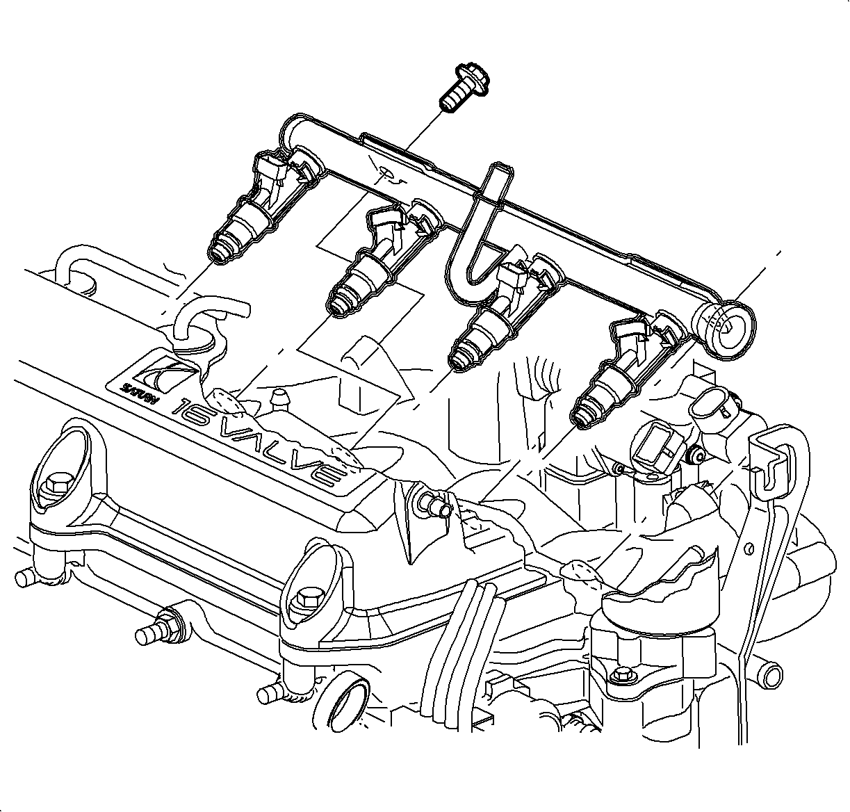
Important: The battery must be at a minimum of 12 volts when performing any fuel system test. Charge battery before proceeding if below 12 volts.

Important: The pressure gage reading should be approximately 276-379 kPa (40-55 psi).
9 - Fuel Injector Balance Test
- On the SOHC (L24), remove the air intake tube.
- Before the Fuel Injector Balance Test is started, the electrical connector should be tested using a J 34730 Noid Lite.
- Connect the SA9127E Gage Bar Set to the fuel test port.
- Connect the SA9182E Electronic Fuel Injection Tester.
- Set the switch on the fuel injector tester to the 50 Pulse - 10 MS setting.
- Cycle the ignition key ON/OFF several times, do not start the engine, and bleed off all the air in the system using the pressure gage shut-off valve.
- Turn the ignition to the OFF position for 10 seconds. After 10 seconds, turn the ignition key to the ON position, do not start engine, and record the gage pressure, 1st reading.
- Using the injector tester, pulse the #1 injector.
- Record the pressure at the instant the gage needle stops moving, 2nd reading.
- Repeat steps 6-9 for the remaining 3 injectors.
- Add all the 2nd Readings together and divide by 4. This is the 2nd reading Average.
- Subtract the Average of 2nd Readings from each 2nd Reading to obtain the Difference .
- An injector is faulty if the Difference is greater than +/- 10 kPa (1.5 psi).
- Check that all fuel injector connectors are connected. Pull back to ensure a positive engagement.
- Remove the fuel gage bar adapter from the fuel pressure test port and recap it.
- Install the air intake tube.
- Start the engine and check for leaks.
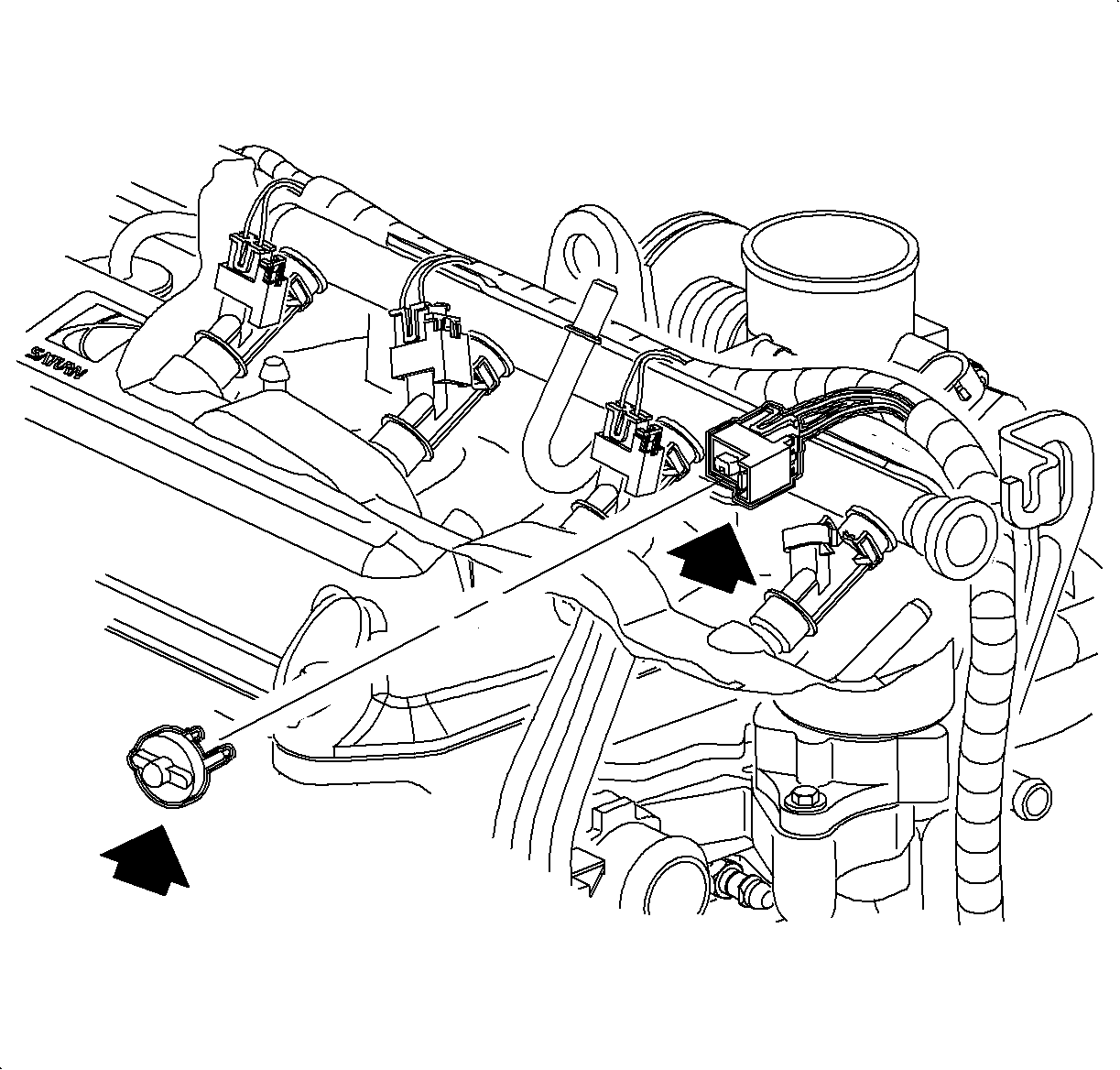
Caution: Do not allow smoking or the use of open flames in the area where work on the fuel or EVAP system is taking place. Anytime work is being done on the fuel system, disconnect the negative battery cable, except for those tests where battery voltage is required.
Important: If the engine is at operating temperature, allow a 10-minute cool down period.
| 2.1. | Disconnect the electrical connectors at the fuel injectors. |
| 2.2. | Connect a Noid Lite to the female connector. |
| 2.3. | Crank the engine. |
| 2.4. | If the Noid Lite does not blink, the electrical problem must be corrected before continuing. |

Caution: Whenever fuel line fittings are loosened or removed, wrap a shop cloth around the fitting and have an approved container available to collect any fuel.
| 4.1. | Connect the plug to a fuel injector. |
| 4.2. | Connect the red clip to the positive battery post. |
| 4.3. | Connect the black clip to a clean ground. |
| 4.4. | Check the power light. If it is not ON, check the battery connection again. |
Important: It may be necessary to cycle the key ON/OFF a minimum of 3 times to bleed all air from the system and achieve maximum system pressure. The key must be OFF 30 seconds.
Notice: The engine must be started after four cylinders have been tested to prevent flooding or internal damage.
EXAMPLE | ||||
Cylinder | 1 | 2 | 3 | 4 |
1st Reading (psi) | 45 | 45 | 45 | 45 |
2nd Reading (psi) | 40 | 42 | 44 | 42 |
Average of 2nd readings (psi) | 42 | 42 | 42 | 42 |
Difference (2nd Reading - Avg of 2nd Readings) | -2 | 0 | 2 | 0 |
Allowable Difference -- +/- 1.5 psi (10 kPa) | ||||
Cylinder #1 is faulty (rich) or too much drop. Cylinder #3 is faulty (lean) or not enough drop. | ||||
