All new Saturn vehicles are certified by the United States Environmental Protection Agency (EPA) as conforming to the requirements of the regulations for the control of air population from new motor vehicles. This certification is contingent on certain adjustments being set to factory standards. In most cases, these adjustment points either have been permanently sealed and/or made inaccessible to prevent indiscriminate or routine adjustments in the field. For this reason, the factory procedure for temporarily removing plugs, caps, etc., for purposes of servicing the product must be strictly followed and, wherever practical, returned to the original intent of this design.
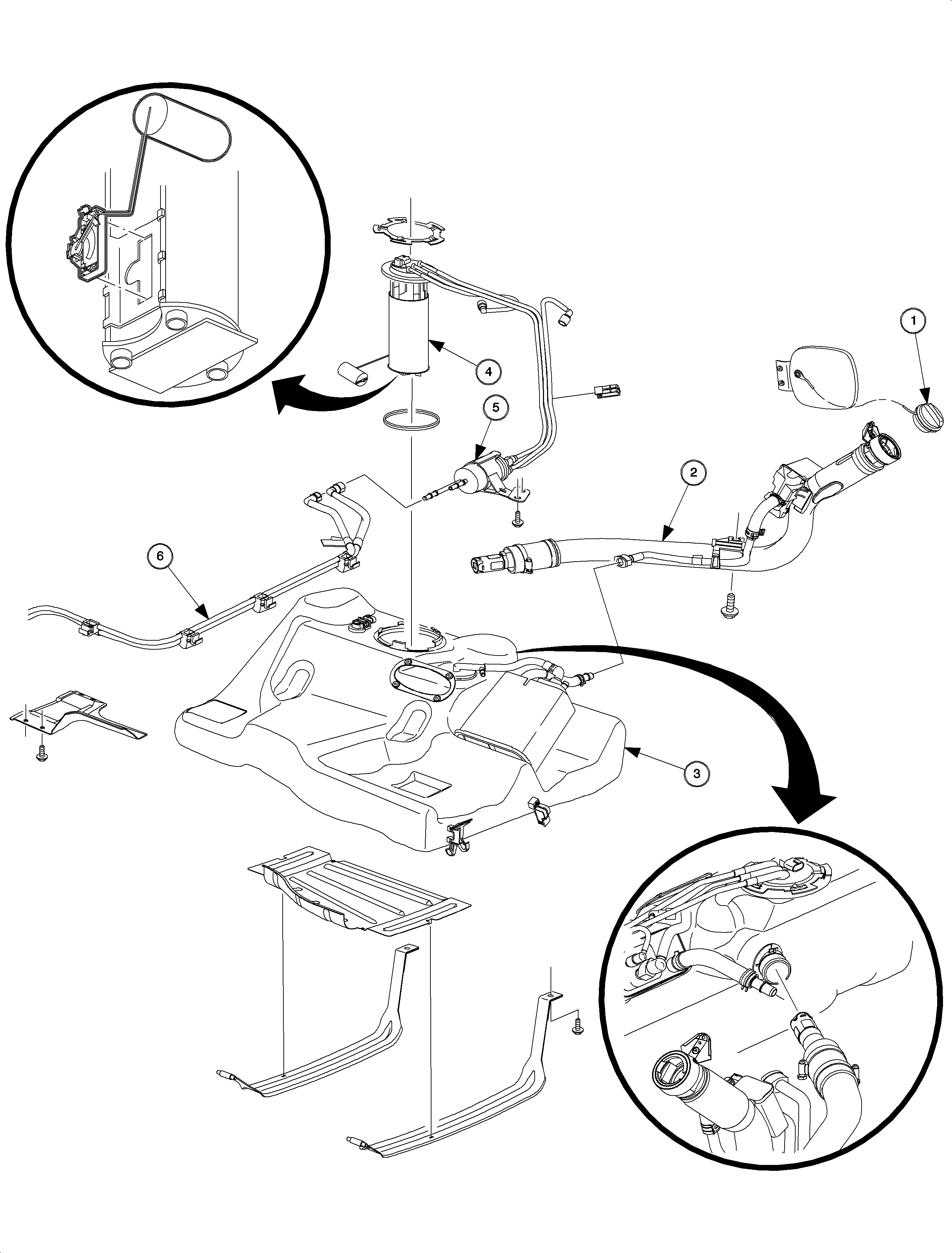
The Saturn fuel system is made up of the components involved in the dispensing, storage, and delivery of gasoline to the engine. It is made up of the following components:
- Fuel filler cap
- Fuel filler pipe
- Fuel tank
- Fuel pump module
- Fuel filter/pressure regulator
- Fuel lines
Multi-Port Fuel Injection (SFI)

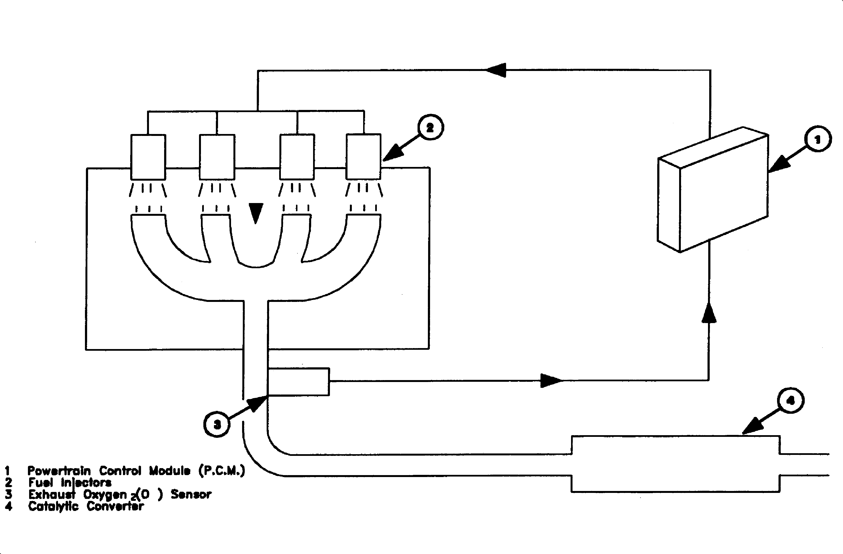
The purpose of the fuel control system is to deliver the correct amount of fuel to the engine under all operating conditions. Fuel is delivered to the engine by individual fuel injectors mounted in the ports of the intake manifold.
The PCM controls the amount of fuel delivered by changing how long the fuel injectors are turned ON and OFF. Injectors are turned ON individually and sequentially before intake valve opening, sequential fuel injection (SFI).
During closed loop operation, the main control sensor is the oxygen sensor, which is located in the exhaust manifold. This sensor indicates to the PCM how much oxygen is in the exhaust gas, and the PCM changes the fuel to the engine based on this information by controlling how long the fuel injectors are pulsed. The best mixture to minimize exhaust emissions is 14.7:1 air/fuel ratio, which allows the three way catalytic converter to operate most efficiently. Because of the constant measuring and adjusting of the air/fuel ratio, the fuel injection system is called a Closed Loop system.
Fuel injector pulses are synchronized with the ignition reference (2X) pulse to the PCM. All fuel injectors are pulsed once each time that the number one cylinder is 60 degrees before top dead center (BTDC).
Modes Of Operation
The PCM uses voltage inputs from several sensors to determine how much fuel to deliver to the engine. The fuel is delivered under one of several conditions, called modes. All of the modes are controlled by the PCM, and are described below.
Starting Mode
When the ignition is first turned to the ON position, the PCM turns ON the fuel pump relay for 2 seconds, allowing the fuel pump to build pressure. The PCM also checks the engine coolant temperature (ECT) sensor and throttle position (TP) sensor to determine the proper air/fuel ratio for starting. This ranges from approximately 0.8:1 at -40°C (-40°F) to 14.6:1 at 104°C (220°F) engine coolant temperature.
Clear Flood Mode
If the engine floods, it may be cleared by pressing the accelerator pedal all the way to the floor. The PCM then completely turns OFF the fuel. The PCM holds this fuel injector rate as long as the throttle stays wide open and the engine speed is below approximately 400 RPM. If the throttle position becomes less than approximately 75 percent, the PCM returns to the starting mode.
Run Mode
The run mode has 2 conditions, called Open Loop and Closed Loop.
Open Loop
When the engine is first started, and engine speed is above 400 RPM, the system goes into Open Loop operation. The PCM ignores the signal from the oxygen sensor, and calculates the fuel required based on inputs from the engine coolant temperature (ECT) and manifold absolute pressure (MAP) sensors. The system stays in open loop until the following conditions are met:
- The oxygen sensor has varying voltage output, showing that it is hot enough to operate properly. This depends on temperature.
- The engine coolant temperature (ECT) sensor is above a specified temperature.
- A specific amount of time has elapsed after starting the engine.
Closed Loop
Specific values for the above conditions exist and are stored in the memory calibration module. When these values are met, the system goes into Closed Loop operation. In closed loop, the PCM calculates the fuel required in the same manner as open loop, but corrects for small errors based on the signal from the oxygen sensor. This allows the air/fuel ratio to stay very close to 14.7:1. The best mixture to minimize exhaust emissions is 14.7:1 air/fuel ration, which allows the three way catalytic converter to operate most efficiently. Because of the constant measuring and adjusting of the air/fuel ratio, the fuel injection system is called a closed loop system.
Acceleration Mode
The PCM responds to rapid increases in throttle position and manifold pressure, providing extra fuel needed for smooth acceleration.
Deceleration Mode
The PCM responds to decreases in throttle position and manifold pressure reducing the amount of fuel. When deceleration is extended, the PCM cuts-off fuel completely when power is not needed.
Battery Voltage Correction Mode
When battery voltage is low, the PCM compensates by:
| • | Increasing the fuel injector pulse width to provide proper fuel |
| • | Increasing the engine idle RPM to increase generator output |
Fuel Cut-Off Mode
To prevent possible engine damage from over-speed, the PCM cuts-off fuel from the fuel injectors when engine speed is above the following RPM:
SOHC (L24) | Auto Trans. | 5750+/-150 |
SOHC (L24) | Manual Trans. | 6000+/-150 |
DOHC (LL0) | Auto/Manual Trans. | 6750+/-150 |
In neutral or while stopped, the engine speed is limited to 4,000 RPM.
