AIR BAG TELLTALE ON WITH DTC 61 IN SENSING & DIAGNOSTIC

SUBJECT: AIR BAG Telltale On with DTC 61 in Sensing and Diagnostic Module ---------------------------------------------------------------- (SDM) Memory (Verify the SDM Connector and CPA Device Are Properly -------------------------------------------------------------------- Installed) ----------
MODELS AFFECTED: 1996 and 1997 Saturns ---------------------
CONDITION: AIR BAG telltale is On with DTC 61 set in the sensing and diagnostic module (SDM) memory.
CAUSE: The SDM connector has a dual-action shorting bar across terminal cavities 6 & 7, which connects the AIR BAG telltale lamp to ground. One end of the dual-action shorting bar is opened when the SDM connector is fully seated in the SDM. The other end of the shorting bar is opened when the CPA device is fully seated in the SDM connector. The CPA device also locks the SDM connector body into the SDM module
If the ignition is turned to the ON position and either the CPA is not fully engaged or the SDM connector is not fully seated, the shorting bar will cause the AIR BAG telltale to turn On and set a DTC 61.
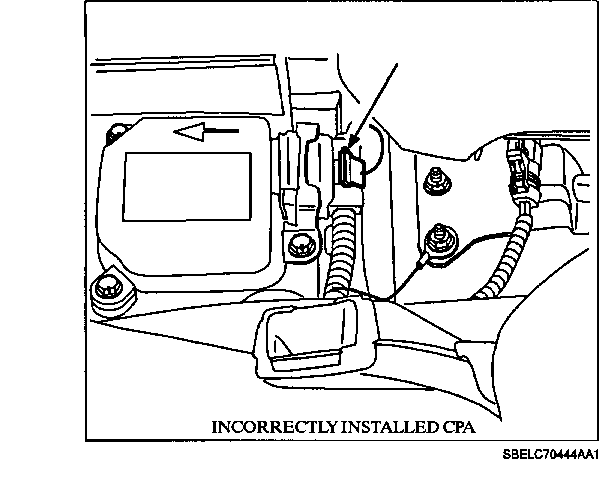
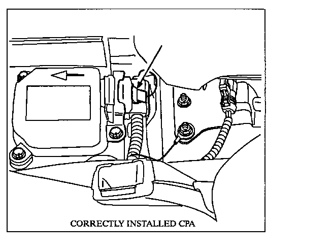
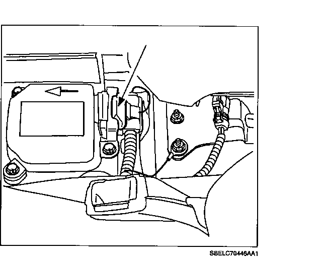
CORRECTION: When performing the "SIR Diagnostic System Check" in the "SIR Service Manual," one of the steps is to check that the SDM connector is properly installed in the SDM and that the connector position assurance (CPA) device is properly installed in the SDM connector. Refer to the following page for checking the SDM's connector position assurance device to make sure it is properly installed. Also, refer to page 3 of this bulletin for added information on how to remove the SDM connector from the SDM.
If the connector and CPA are installed correctly, refer to appropriate diagnostic chart in the appropriate year "SIR Service Manual."
PROCEDURE
CAUTION:
WHEN YOU ARE PERFORMING SERVICE ON OR NEAR THE SIR COMPONENTS OR THE SIR WIRING, YOU MUST DISABLE THE SIR SYSTEM. REFER TO THE DISABLE PROCEDURE IN THE SIR SERVICE MANUAL TO TEMPORARILY DISABLE THE SIR SYSTEM. FAILURE TO FOLLOW THE CORRECT PROCEDURE COULD CAUSE AIR BAG DEPLOYMENT, PERSONAL INJURY, OR UNNECESSARY SIR SYSTEM REPAIRS. THE INFLATABLE RESTRAINT SENSING AND DIAGNOSTIC MODULE MAINTAINS A RESERVE ENERGY SUPPLY. WHEN THE VEHICLE POWER IS INSUFFICIENT TO CAUSE DEPLOYMENT OF THE AIR BAGS, THE RESERVE ENERGY SUPPLY PROVIDES THE DEPLOYMENT POWER. DEPLOYMENT POWER IS AVAILABLE FOR AS MUCH AS TEN MINUTES AFTER DISCONNECTING THE VEHICLE POWER BY ANY OF THE FOLLOWING METHODS.
- YOU TURN OFF THE IGNITION SWITCH.
- YOU REMOVE THE FUSE THAT PROVIDES POWER TO THE INFLATABLE RESTRAINT SENSING AND DIAGNOSTIC MODULE.
- YOU DISCONNECT THE VEHICLE BATTERY FROM THE VEHICLE ELECTRICAL SYSTEM.
When checking the SDM connector, make sure that the CPA device is completely inserted into the SDM connector. If the CPA device is not completely inserted into the SDM connector, the shorting bar will not be opened, and the CPA device will not function as a lock for the SDM connector.
When inserting the CPA, make sure that the CPA clicks into place and that the top of the CPA is totally flush with the SDM connector. (Refer to the two illustrations above.)
Sensing and Diagnostic Module (SDM) Connector Removal
IMPORTANT: The SDM connector has been intentionally designed with higher than normal insertion and removal force characteristics to prevent the connector from inadvertently disengaging. When disconnecting the SDM connector from the SDM, refer to the following procedure.
1. Once the SDM connector has been accessed, remove the connector position assurance (CPA) device and then push connector inward toward the SDM, to seat the connector. (This allows the connector lock ramps to move freely.)
2. Once the connector has been seated, depress connector strain relief housing "Dome" to free up the lock ramps. (The dome is located directly above the connector lock release.)
3. While holding the connector strain relief housing dome downward against the connector body, remove connector.
Sensing and Diagnostic Module (SDM) Connector Assembly
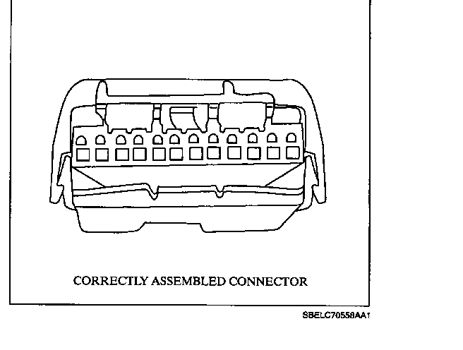
The SDM connector is assembled from basically three parts:
- The connector body (P/N 12188017) that contains the terminals for all of the SDM wiring.
- A "clamshell" housing that surrounds the connector body and serves as a terminal position assurance (TPA) device.
- A tethered connector position assurance (CPA) device (P/N 12191277).
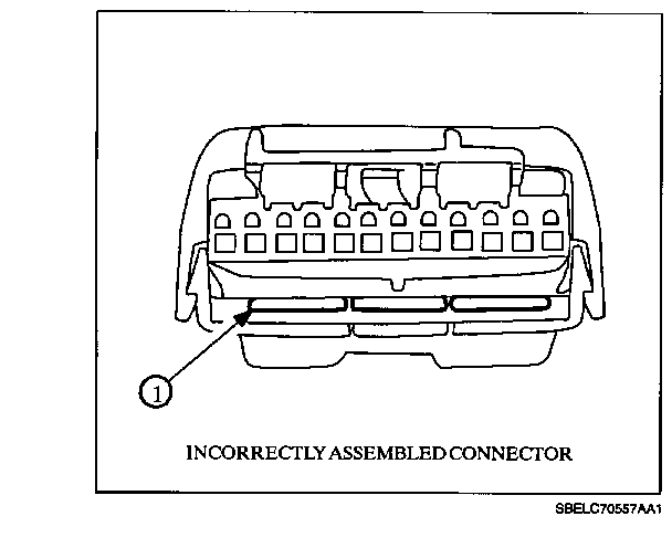
When assembling these three parts, care must be taken to slide the connector body into the "clamshell" housing so that the terminal position provision (1) is inserted into the connector body. The following connector views illustrate correct and incorrect SDM connector assembly.
General Motors bulletins are intended for use by professional technicians, not a "do-it-yourselfer". They are written to inform those technicians of conditions that may occur on some vehicles, or to provide information that could assist in the proper service of a vehicle. Properly trained technicians have the equipment, tools, safety instructions and know-how to do a job properly and safely. If a condition is described, do not assume that the bulletin applies to your vehicle, or that your vehicle will have that condition. See a General Motors dealer servicing your brand of General Motors vehicle for information on whether your vehicle may benefit from the information.
