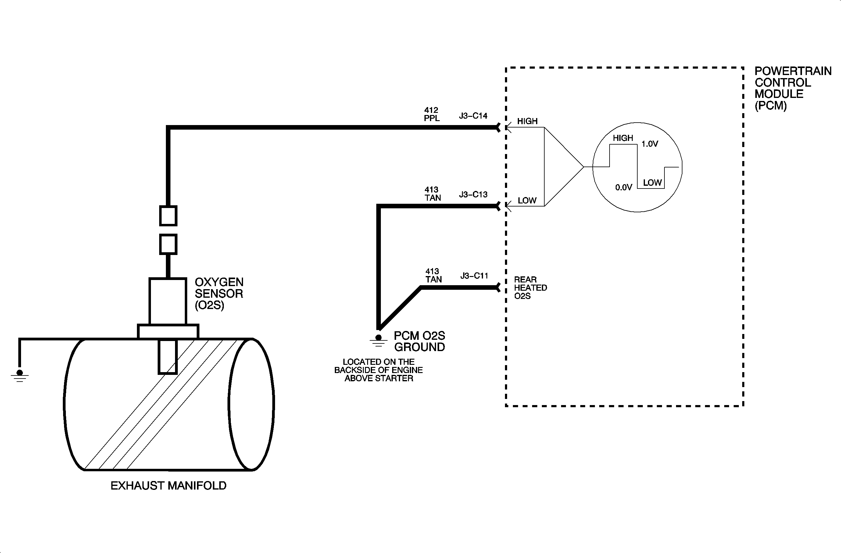
Circuit Description

After achieving closed loop fuel control, a commanded air fuel ratio of 14.7:1, RPM between 1,500-3,200, and air flow between 7-25 grams per second, the PCM will continuously monitor the front oxygen sensor signal for 100 seconds. During this time, the PCM counts the number of rich to lean and lean to rich switches. To be considered a switch, the voltage must go below 300 mv and above 600 mv. The PCM also keeps track of the time it takes to make the switch. The number of switches along with the time to achieve these switches are used to calculate the average response time to perform each switch. Also this information is used to calculate if the proper ratio of the switches is correct. The 3 diagnostic trouble codes listed below are used to identify different types of faults that can occur with oxygen sensors.
Conditions for Setting the DTC
DTC P0133: This DTC is set if the average response time of the switches from the sensor is too slow after the 100 second test is performed. If the lean to rich time is greater than 125 ms or the rich to lean time is greater than 156 ms, this code will set.DTC P1133: If less than 10 switches take place during the test, this code will set.
DTC P1134: If the transition ratio of the sensor is greater than 2.8 or less than 0.6, this DTC will set.
Diagnostic Aids
Repair Procedure
- The oxygen sensor wiring and connections should be checked if any of these DTCs are set because corrosion or loose connections could cause these DTCs to set.
- The most likely cause of setting any of these DTCs is contamination. This contamination could be caused by fuel, improper use of RTV sealant, engine oil, or coolant contamination.
- The source of contamination should be identified and corrected before replacing the sensor.
