Circuit Description

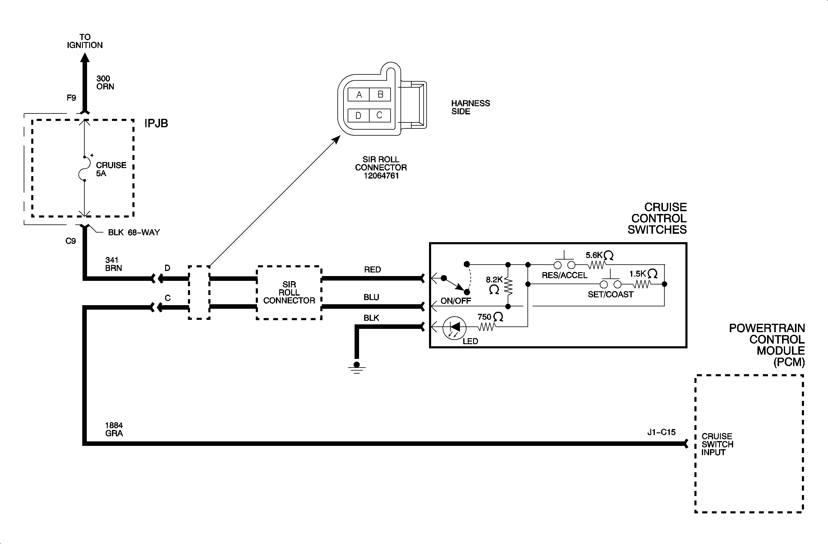
Command state voltage levels are divided through a resistor network from ignition
voltage provided through the 5A cruise fuse. The network consists of resistors
both in the cruise control switch and internal powertrain control module (PCM). If
the voltage level is within an acceptable window for all 3 switches, the PCM
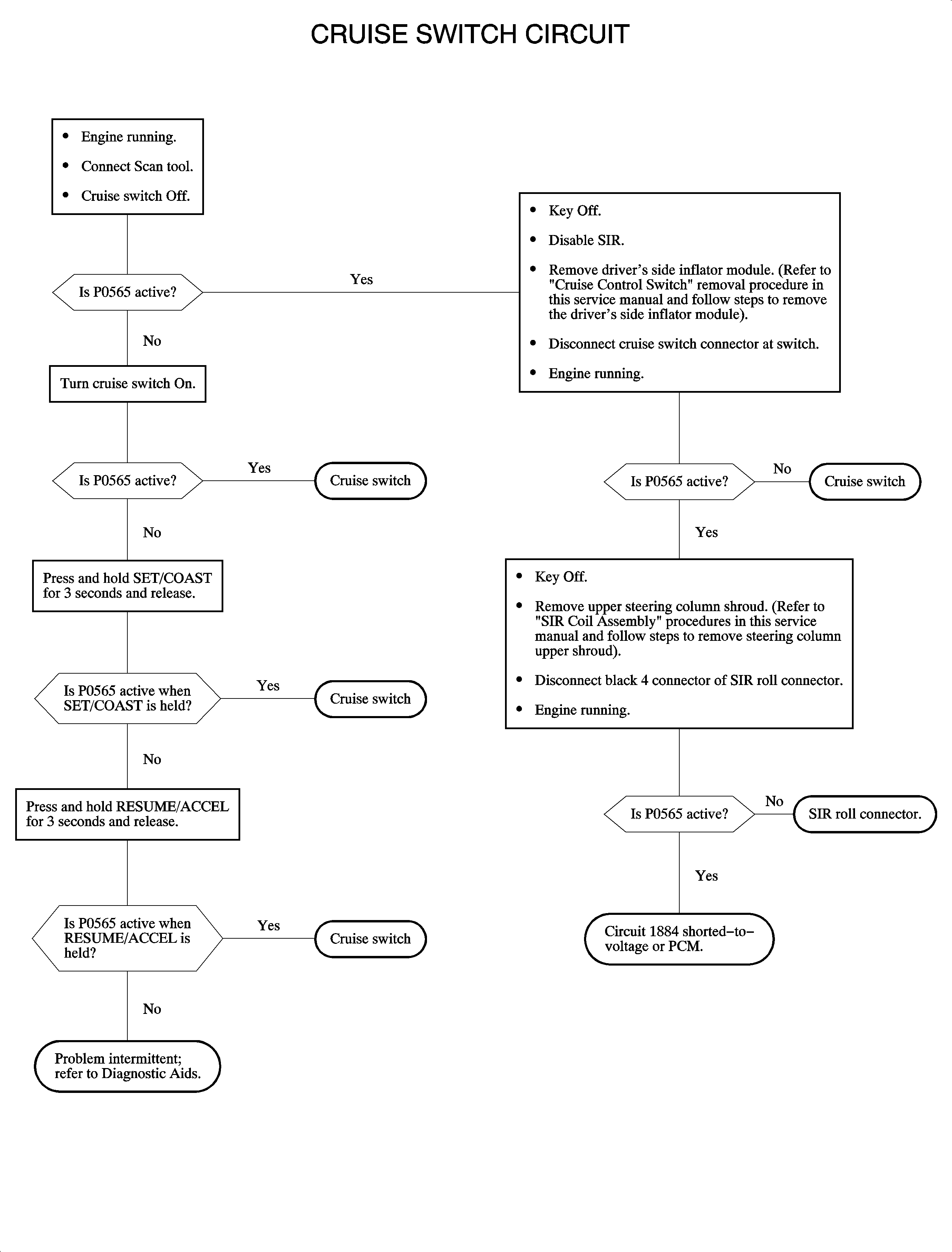
decodes the command. If voltages are outside the windows, DTC P0565 will set.
Conditions for Setting the DTC
Important: Voltage windows vary dependent to B+ calculations.
DTC will set if:
| • | Cruise switch ON less than 0.5 volts or greater than 1 volt
at circuit 1884. |
| • | RESUME/ACCEL switch depressed, less than 1.2 volts or greater than
1.7 volts at circuit 1884. |
| • | SET/COAST switch depressed, less than 3 volts or greater than 3.5 volts
at circuit 1884. |
Diagnostic Aids
| • | Inspect malfunction history data. Attempt to distinguish which portion
of the switch input was lost. Attempt to reproduce it. |
| • | Shorts high or low in circuit 1884 will result in an inoperative
system. |
| • | Intermittents: Inspect the harnesses, observe the parameters on the scan
tool while moving the harnesses and connectors. |


