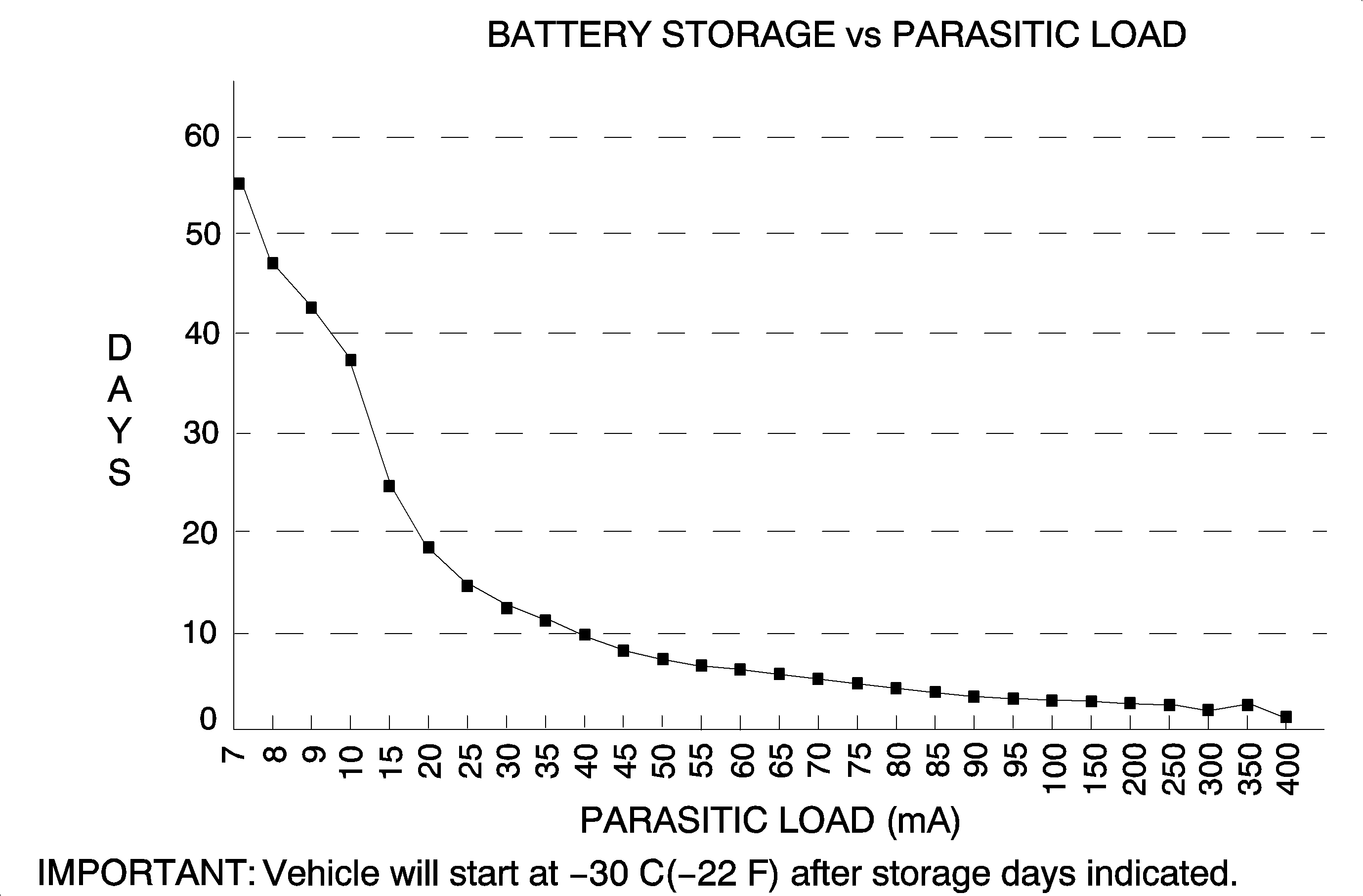
Small current drains, called parasitic drains, constantly draw current from the battery even with the ignition switch in the OFF position. These parasitic drains can discharge a battery in four to six weeks depending on the battery's state of charge and when the vehicle went into storage.
For normal parasitic current drain, refer to individual component parasitic loads. Remember, when checking for parasitic current draw, take a look to see what types of equipment the customer may have had installed on the vehicle. A cellular phone, anti-theft system, or any device added, that requires constant voltage to retain a memory, will draw current at all times. So take these added accessories into account when testing for parasitic current drain.
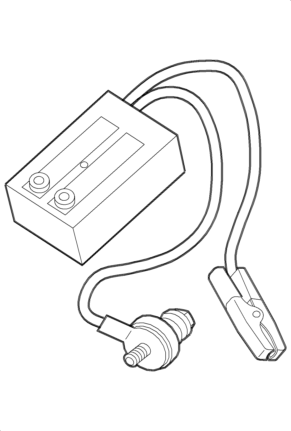
Saturn Parasitic Load Test Device
The SA9130Z Parasitic Load Test Device is used with a digital multimeter. The test device is used to measure parasitic current drain from the battery with the ignition and all accessories OFF. The load tester, constructed with 1 ohm resistance and built-in circuit protection devices, opens when the current exceeds approximately 1 amp. When the circuit is opened, the user is alerted by a red light-emitting diode (LED) indicator. The parasitic load test device is put into the circuit between the negative battery terminal and the negative battery cable so it effectively becomes a load in series with all other vehicle loads.
- Turn the ignition and all accessories OFF and remove the key from the ignition switch.
- Disconnect the cable from the negative battery terminal.
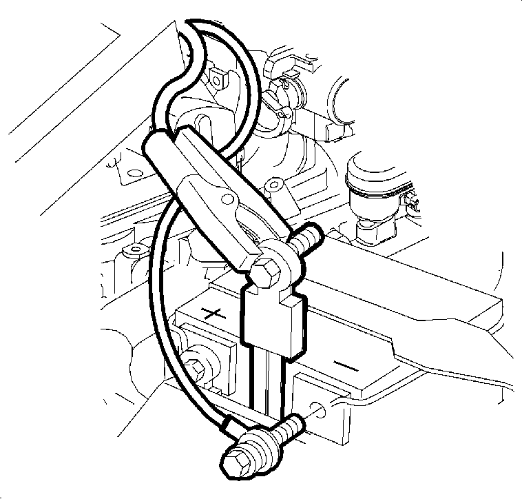
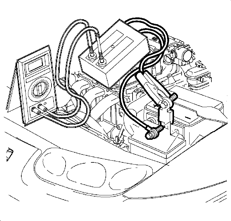
- Install the parasitic load tester between the negative cable and the negative battery terminal so that the 1 ohm resistor is in series with the other resistances.
- Set the multimeter to the MILLIVOLT scale.
- Measure the current across the tester by putting the multimeter probes on two terminals on the end of the tester. The reading obtained is in volts. This reading is directly converted to milliamps. Should the parasitic current draw exceed 1 amp, the LED indicator on the test device will light. This may indicate that a vehicle accessory is ON. For normal parasitic current drain, see the next page for individual component parasitic loads.
- To find the source of the excessive load, start removing the fuses and modules in a systematic way. When the voltage drops across the tester, the circuit or circuits protected by that fuse is the source of the current drain.
- Remove the fusible link from the generator to check for a voltage drop. If the voltage drop is greater than 2 volts replace the generator.
- Repair the circuit and perform the parasitic load test again to verify the repair.

Important: The fog lamp switch must be in the OFF position before load testing. In the ON position, the fog lamp switch consumes about 6 miliamps of current draw regardless of the park ignition switch position or whether the key is in the ignition.
Important: The ignition key must be removed from the cylinder before parasitic load testing. The key minder circuit is activated by the key cylinder switch when the key is in the ignition cylinder, which adds 20 milliamps of current draw.
Important: The alligator clamp on the parasitic load test device must be connected to the flat pad part on the negative battery cable. Do not connect the alligator clamp to the bolt on the negative battery cable. This will cause incorrect readings.

Parasitic Current Drain Testing With An Ammeter
- Turn the ignition and all accessories OFF.
- Disconnect the cable from the negative battery terminal.
- Follow the manufacturers instructions for the multimeter or ampmeter being used. This could involve plugging the leads into different locations on a multimeter and changing the scale to read amperage. On some testers you should start on the 10 AMP scale setting, and after verifying that the current drain is less than two milliamps, set the scale to 200 milliamps or 20 milliamps.
- Connect the ampmeter between the negative cable and the negative battery terminal so that it is in series. Read the parasitic current drain from the battery.
- To find the source of the excessive load, start removing the fuses in a systematic way. When the voltage drops across the tester, the circuit or circuits protected by that fuse is the source of the current drain.
- Repair the circuit and perform the parasitic load test again to verify the repair.
Important: Typical parasitic load for the vehicle is 10-15 mA. If the vehicle does not have one of the following components, then subtract the parasitic load of the component from the total vehicle parasitic load (10-15 mA) to determine the load range for the vehicle being tested.
Typical Parasitic Loads | |
|---|---|
PCM | 1 mA |
Generator | 0-1 mA |
Radio | 2.8-4.3 mA |
BCM | 1-3.5 mA |
CD Changer | 3 mA *See note on the next page. |
Remote Keyless Entry | 2.75 mA |
I/P Cluster flashing "Security" telltale | 1.2 mA |

Important: During CD changer initialization, the parasitic current draw will fluctuate between 3 mA-1 A. The initialization period lasts up to a maximum of 90 seconds. After initialization, the CD changer parasitic current draw will stabilize at approximately 3 mA.
If the CD changer door is open and the light is illuminated, the parasitic current draw will be approximately 65 mA. The light will remain on for two minutes. After the light goes out, the CD changer parasitic current draw will stabilize at approximately 3 mA.
Typical Undesired Parasitic Loads
| • | Park lamps ON |
| • | Headlamps ON |
| • | Dome lamp ON |
| • | Map lights ON |
| • | Cargo lamp ON |
| • | Radio ON |
| • | Cigar lighter ON |
| • | Fog lamp switch ON, will draw current even with ignition switch OFF |
