Tools Required
| • | SA9127E Gage Bar Set |
| • | SA9603E Oxygen Sensor Wrench Remover/Installer |
Removal Procedure
- Raise the vehicle squarely on a lift.
- Remove the HO2S-2 wiring harness from the cradle by pushing up on the retaining clip tab.
- Remove the connector position assurance (CPA) device and disconnect the HO2S-2 harness connector.
- Remove the HO2S-2 wiring harness from the trough in the converter heat shield by gently pulling the wiring harness from its retaining clips.
- Remove HO2S-2 using the SA9127E . If necessary, use a liquid penetrate before removing the sensor.
- Remove the3 front exhaust pipe nuts at the manifold.
- Loosen the front exhaust pipe clamp (15 mm hex) at the engine block bracket and slide the clamp out of engagement with the bracket.
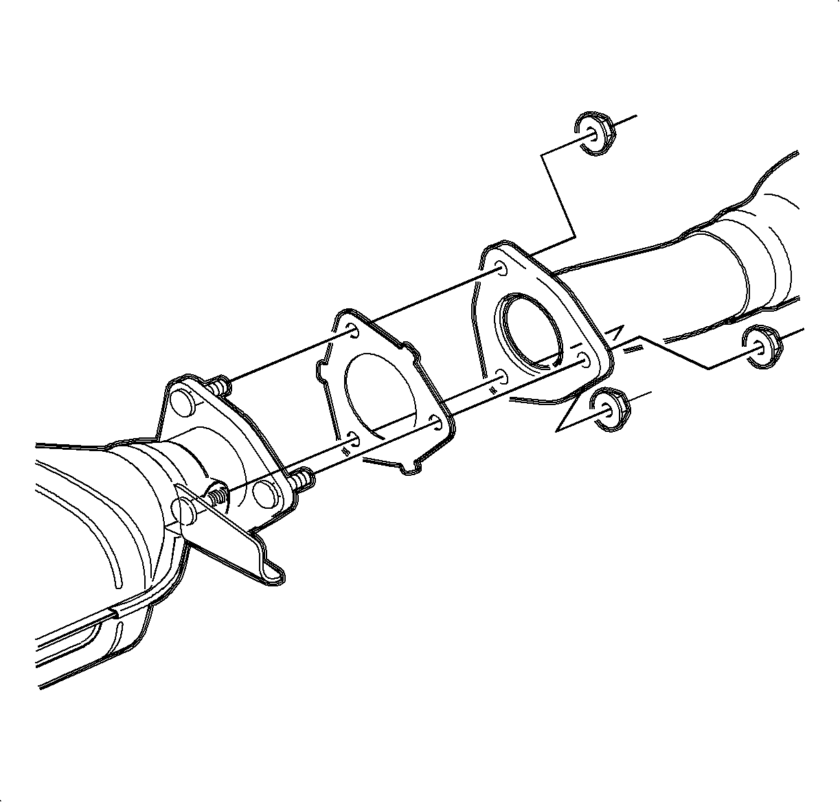
- Remove the nuts at the outlet of the catalytic converter to intermediate pipe.
- Disengage the 2 rubber isolators from the hanger rod on the front exhaust pipe and remove the pipe from the vehicle
- Inspect the front exhaust pipe-to-exhaust manifold flange.

Caution: Ensure that the vehicle is properly supported and squarely positioned. To help avoid personal injury when a vehicle is on a hoist, provide additional support for the vehicle on the opposite end from which the components are being removed.
Important: The front exhaust pipe and catalytic converter are only serviced as an assembly; components are not serviced separately.
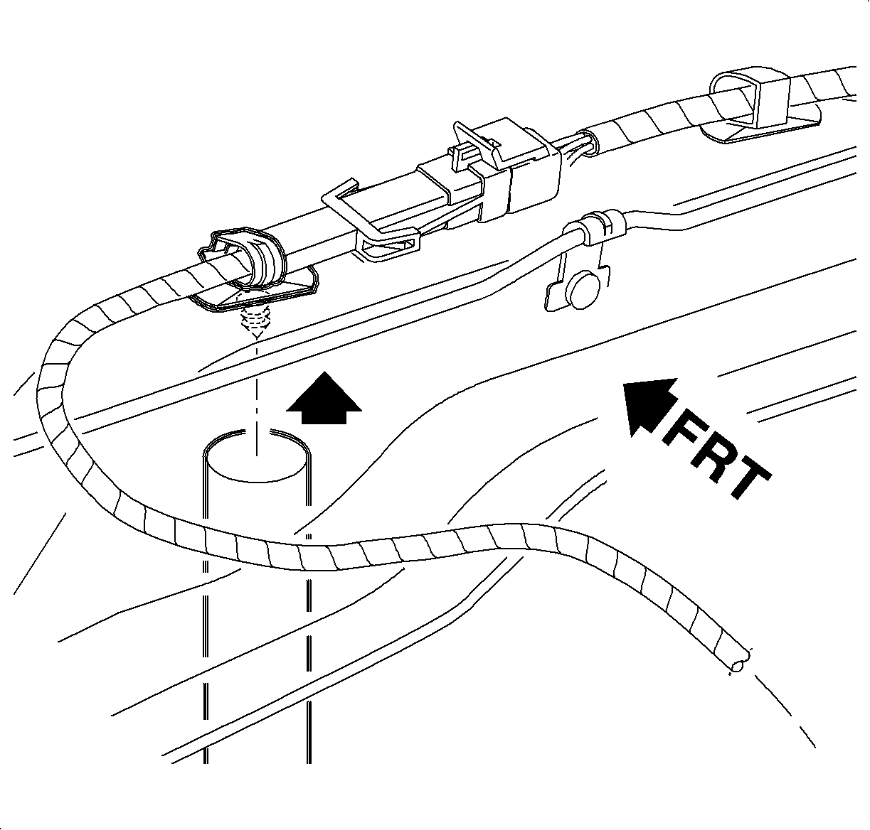
Notice: Do not apply grease or silicon products to the heated oxygen sensor (H02S-2). Do not alter the wiring in any way. The wires carry air reference to the sensor.
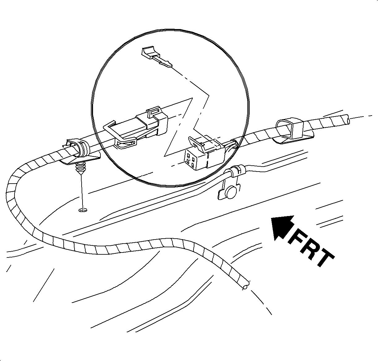
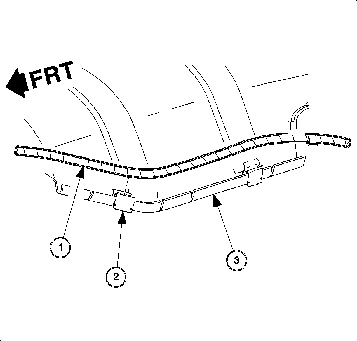
Important: The HO2S-2 uses a permanently attached pigtail and connector. This pigtail should not be removed from the sensor. Damage or removal of the pigtail or connector will affect proper operation of the sensor.
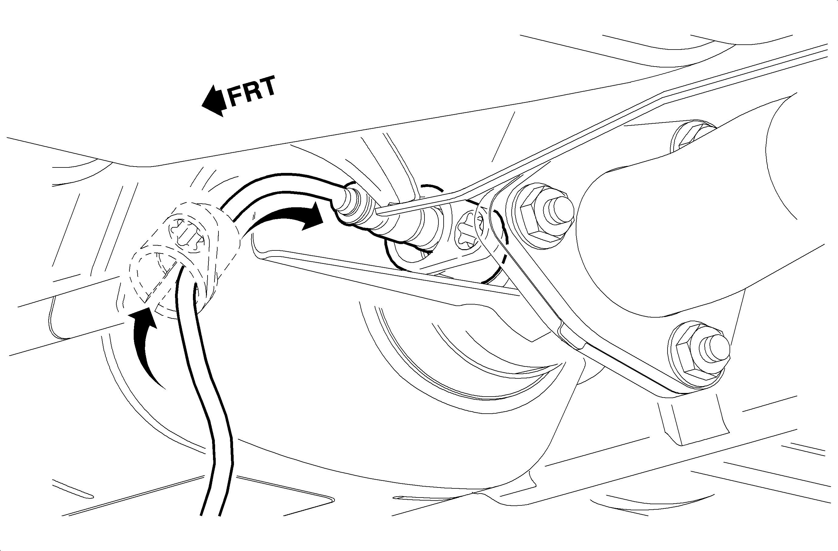
Front Exhaust Pipe to Manifold Flange Warpage:
Service Limit: 0.7 mm (0.028 in) max.
Standard: 0.7 mm (0.028 in) max.
Installation Procedure
- Install a new gasket on the exhaust manifold studs.
- Install the 2 rubber isolators supporting the front exhaust pipe to hanger rod on the pipe.
- Install the front exhaust pipe-to-manifold nuts.
- Slide the front exhaust pipe clamp over the engine block bracket and tighten the clamp.
- Install the catalytic converter outlet gasket and fasten the outlet to intermediate pipe with the nuts.
- Install heated oxygen sensor (HO2S-2) using the SA9603E .
- Attach the HO2S-2 harness to the clips on the converter heat shield.
- Connect the HO2S-2 harness to the connectors and install the connector position assurance clip.
- Install the tab on the harness connector to the hole in the engine cradle.
- Lower the vehicle to the ground, start the engine, and check for exhaust leaks.
Notice: When installing a replacement front exhaust pipe and catalytic converter assembly, three bolts and three nuts will be required to make the installation to the intermediate pipe. The replacement front exhaust pipe has a 6-hole flange at the outlet of the converter vs. three studs on the production assembly.
Tighten
Tighten the exhaust pipe-to-manifold to 31 N·m (23 lb ft).
Notice: When installing a replacement front exhaust pipe, procure an exhaust pipe hanger clamp for installation on the pipe.
Tighten
Tighten the exhaust pipe clamp-to-support bracket to 60 N·m (44 lb ft).
Tighten
Tighten the catalytic convertor-to-isolator to 25 N·m (19 lb ft).

Notice: Always use a nickle-based anti-seize compound Saturn P/N 21485279 (or equivalent) on the threads of the heated oxygen sensor (H02S-2). If the H02S-2 is replaced, do not apply anti-seize to the new sensor. New sensors have anti-seize pre-applied. Never use silicone products. Silicone products will damage the sensor.
Tighten
Tighten the sensor - oxygen-to-exhaust manifold to 45 N·m (33 lbs ft).
