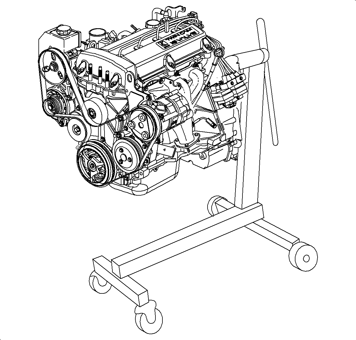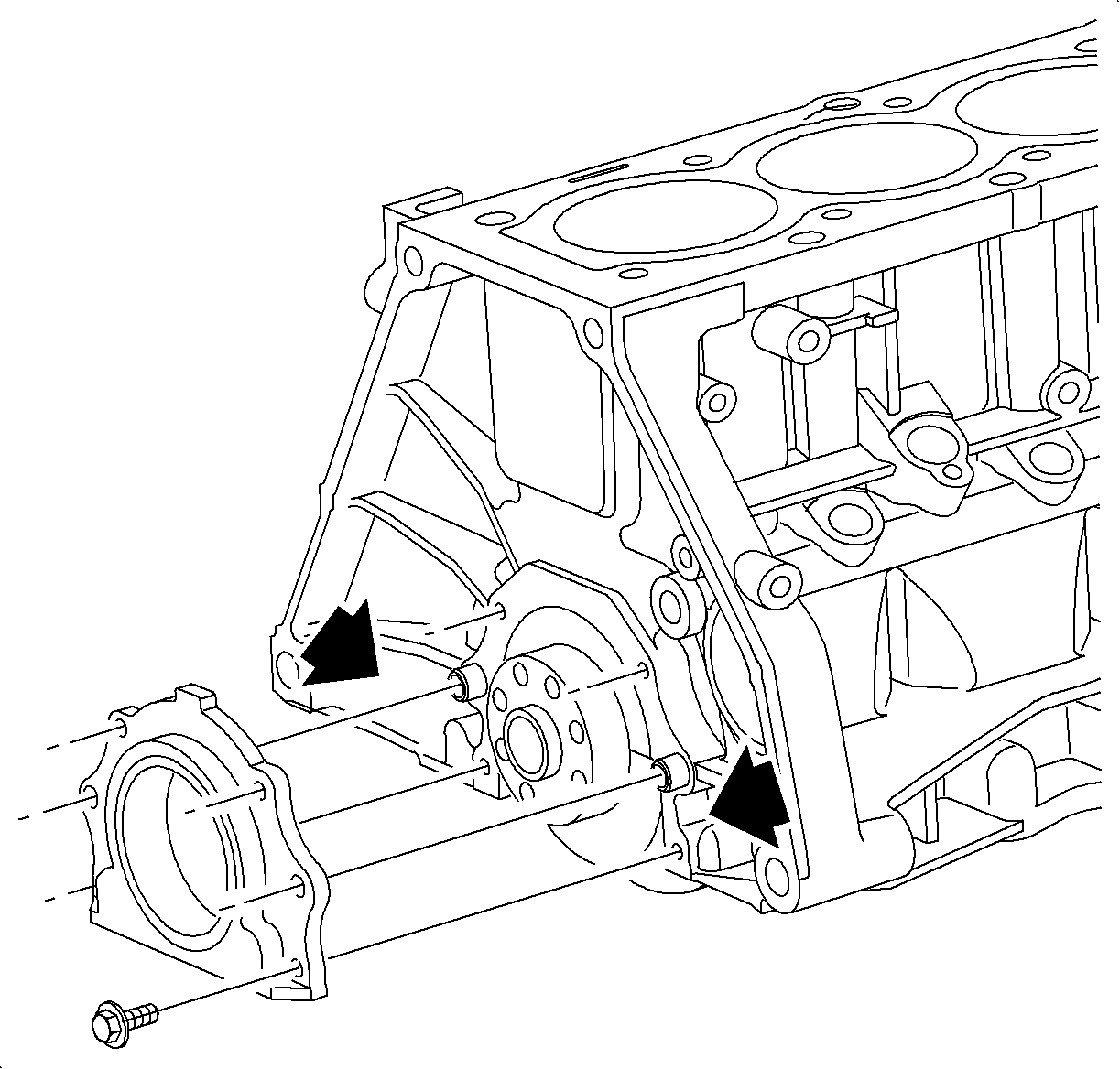
- Remove rear oil seal carrier.
Remove the four bolts and rear oil seal carrier. Pry tangs are located on both
sides of the rear seal carrier. A rolling head pry bar or pinch bar will separate
the carrier from the cylinder block, use care not to damage the sealing surface.
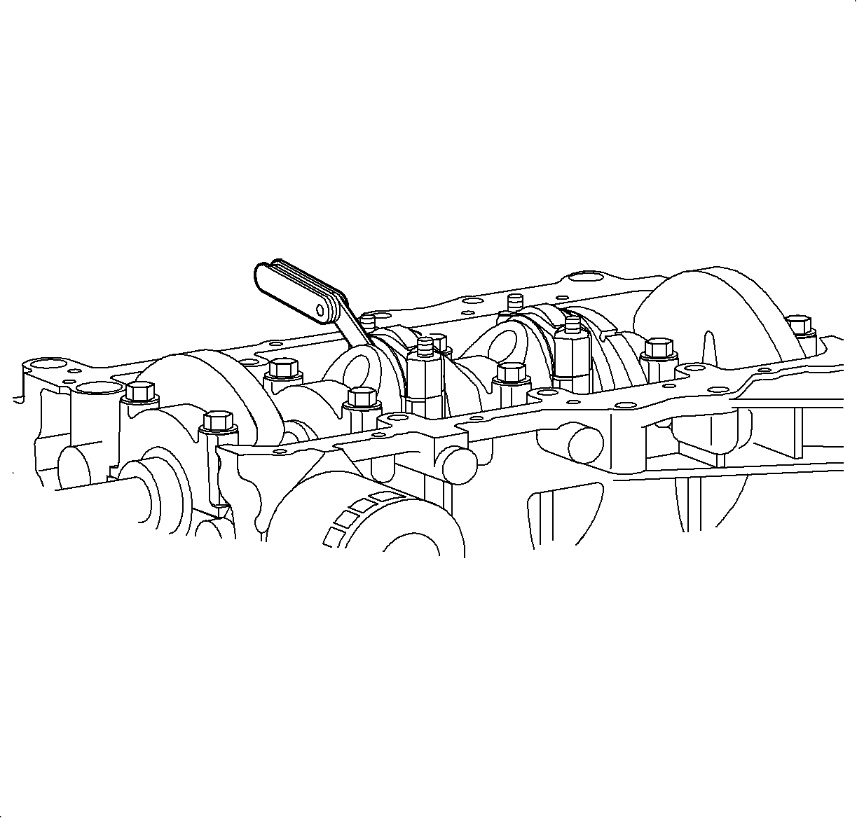
- Check connecting rod side clearance vertically along side the rod:
Using a SA9179NE
or equivalent
or a SA91101NE
or equivalent,
measure the side clearance while moving the rod back and forth.
Side Clearance
| • | Standard: 0.165-0.435 mm (0.0065-0.01713 in) |
| • | Service Limit: 0.470 mm (0.0185 in) max. |
Important: Connecting rods and caps are identified with a serial number during manufacture
to prevent interchanging of parts.
- Remove connecting rod caps and check oil clearance.
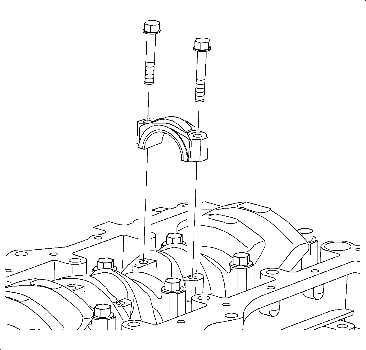
Important: Do not pull the piston assembly down through the cylinder bore beyond its normal
travel. The oil control rings can lodge between the bottom of the cylinder liner
and machined step in block, and act as a snap ring, holding the piston firmly in place.
Cylinder liner removal is required to free the piston.
Important: Keep the lower bearing inserted in the connecting rod cap.
- Remove the connecting rod caps.
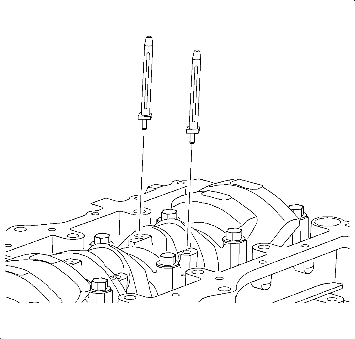
Important: Do not remove the connecting rod and piston assembly until all measurements
are taken and the cylinder ridge has been removed, if present.
- Install the J 41742
to
protect the crankshaft from damage during piston and connecting rod assembly removal.
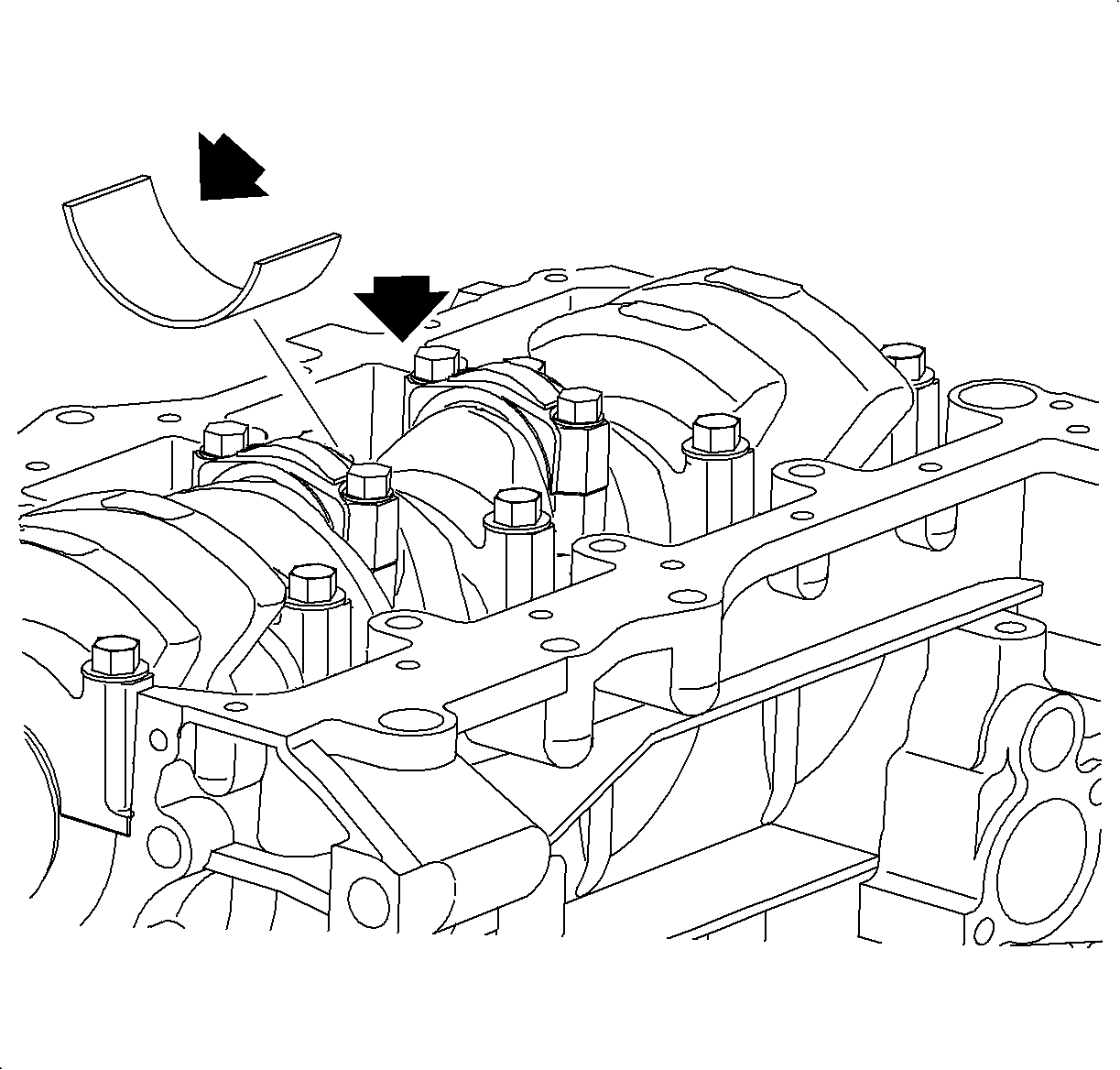
- Clean rod journal and bearing.
Important: If the crank pin, connecting journal, or bearings are damaged, replace the bearings.
If necessary, grind the connecting rod journals or replace the crankshaft. 0.25 mm
(0.01 in) undersized crankshaft bearings are available for crankshaft repair.
- Check the crank pin and bearing for pitting and scratches.
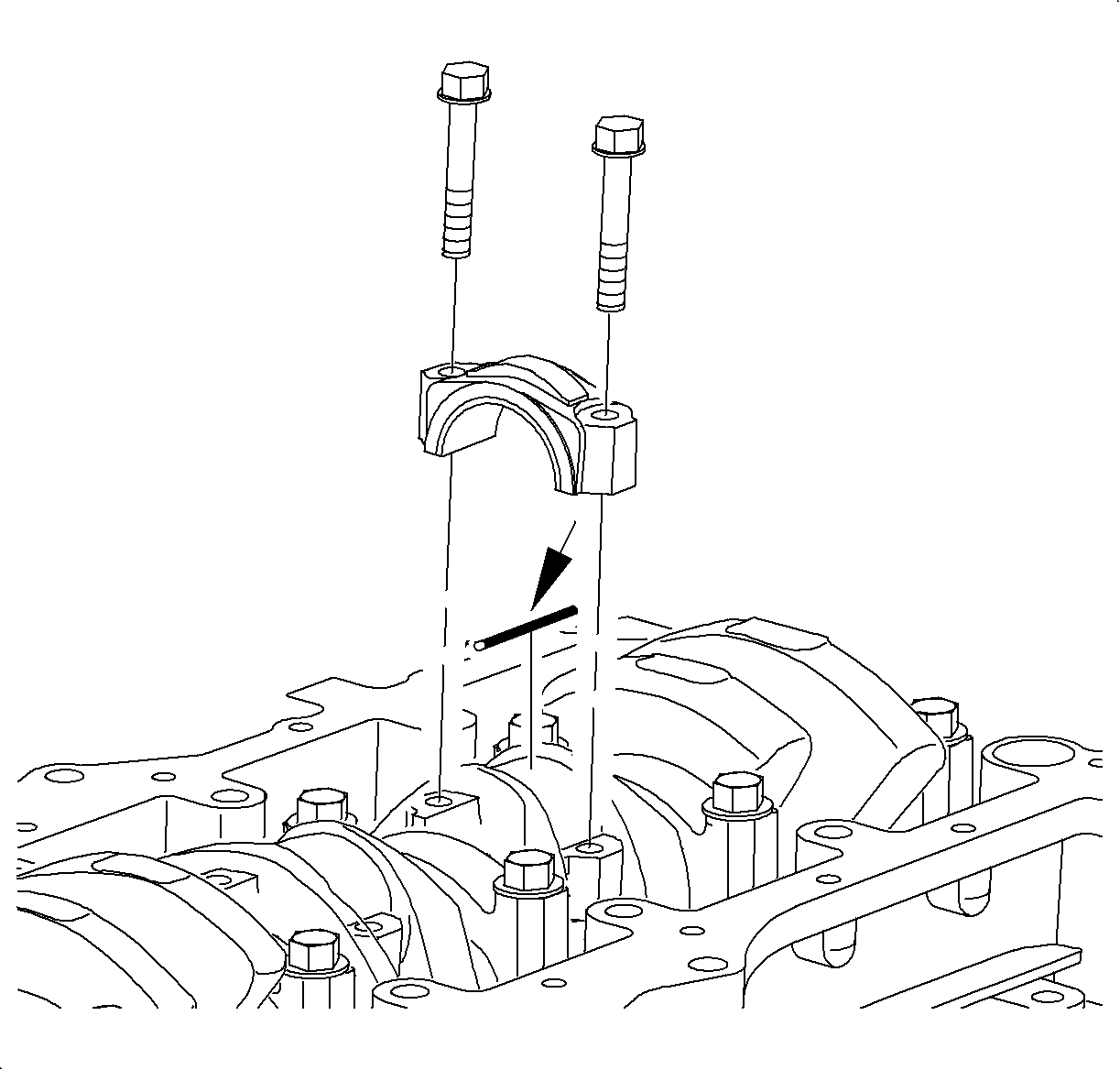
Important: The connecting rod bolts are torque-to-yield fasteners. It is acceptable to
use the original rod bolts when using Plastigage® , or equivalent to determine
crankshaft pin clearance. New bolts, which have never been tightened, must be used
when the connecting rod and rod cap are final assembled in the engine.
- Lay a strip of Plastigage®, or equivalent across the rod journal.
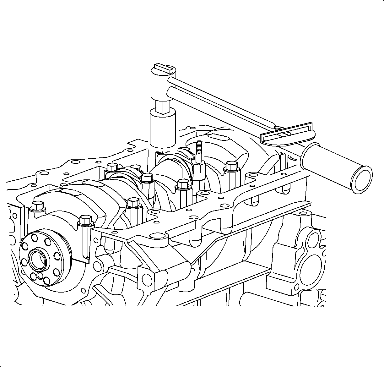
Important: Do not turn the crankshaft when there is a Plastigage®, or equivalent strip
between the bearing and crankshaft journal.
- Install connecting rod cap.
Tighten
Tighten the connecting rod cap-to-rod to 25 N·m (19 lb ft)+75 degrees.
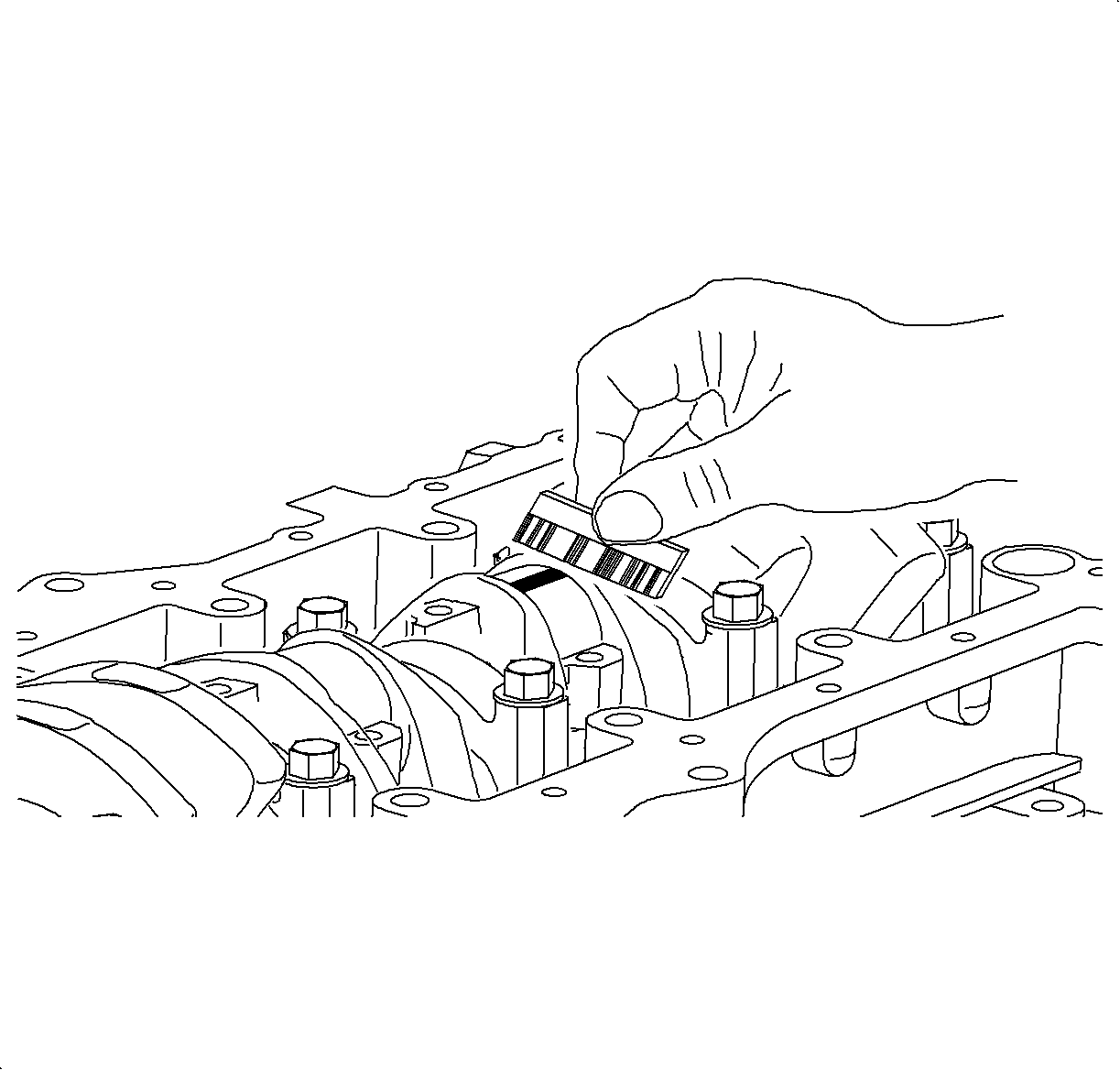
- Remove the connecting rod cap.
- Measure the Plastigage®, or equivalent at its widest point.
Rod Journal Oil Clearance
| • | Standard: 0.003-0.053 mm (0.0001-0.0021 in) |
| • | Service Limit: 0.055 mm (0.0022 in) max. |
| • | If the oil clearance is greater than maximum, replace the bearings. If necessary,
grind the connecting rod journals or replace the crankshaft. |
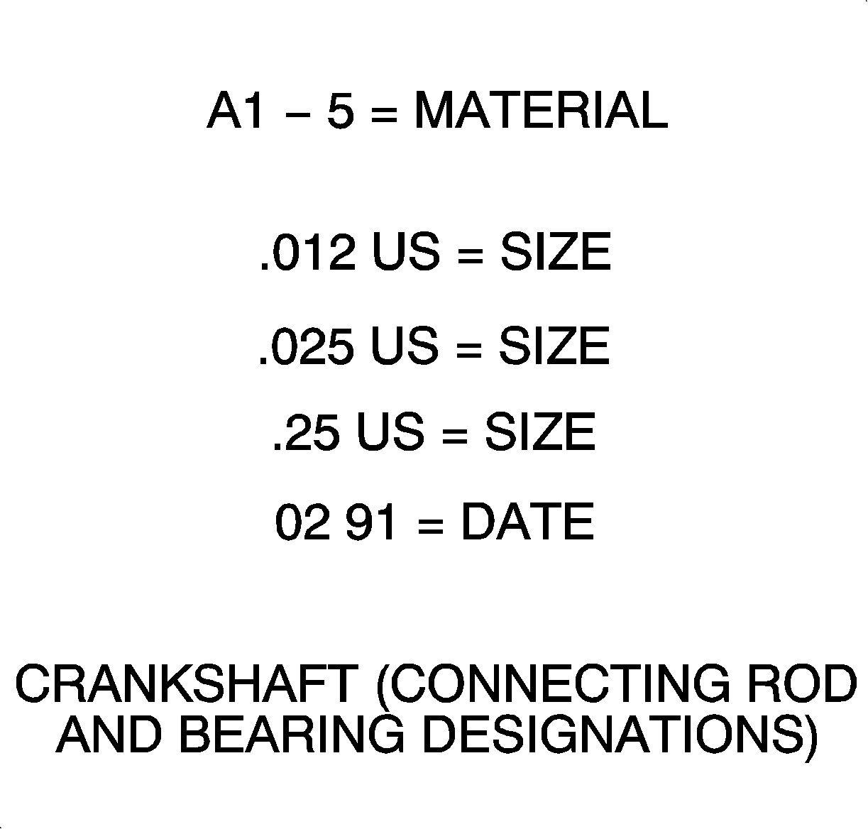
- Completely remove
the Plastigage®, or equivalent.
Important: There are three bearing sizes available, (standard, 0.012 mm (0.0005 in),
and 0.025 mm (0.001 in) to adjust fro correct connecting rod bearing
oil clearance. 0.25 mm (0.01 in) undersized bearings are available
for crankshaft repair.
Important: Do not pull the piston assembly down through the cylinder bore beyond its normal
travel. The oil control rings can lodge between the bottom of the cylinder liner
and machined step in block, and act as a snap ring, holding the piston firmly in place.
Cylinder liner removal is required to free the piston.
- Complete the procedure on the rest of the bearings.
- Remove piston and connecting rod assemblies. Do not pull the pistons down
through the cylinder bore beyond their normal travel.
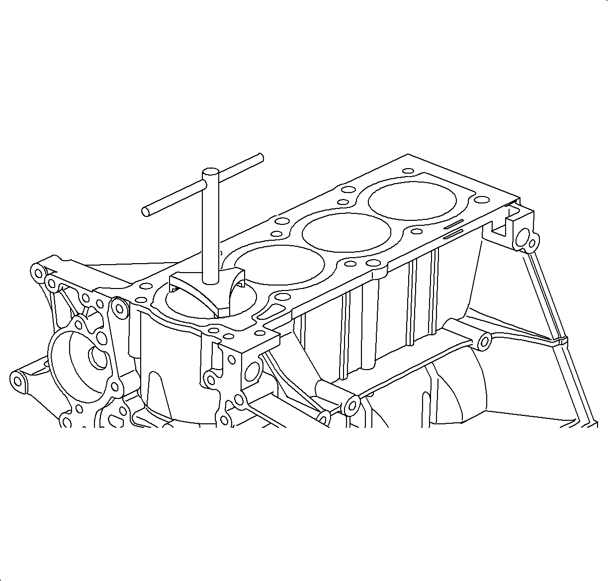
Notice: When removing a ridge in the cylinder, do not damage the top of a cylinder bore.
- If a ridge can be felt at the top of the cylinder bore, it must
be removed. If necessary, install cylinder ridge reamer and remove the ridge at the
top of the bore per the manufacturer's instructions.
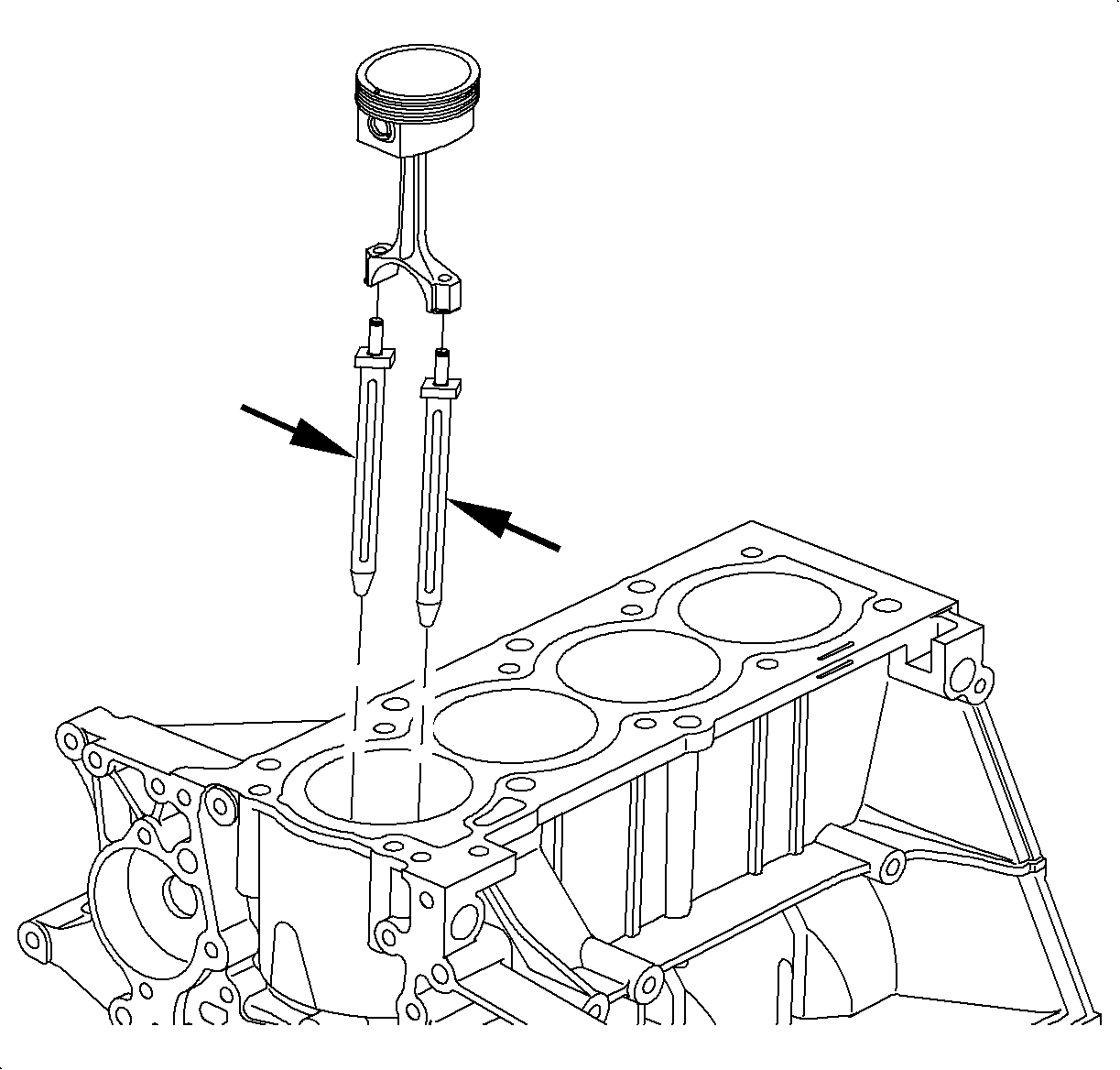
- Make sure the J 41742
are
installed to protect the crankshaft from damage.
- Push out the piston and connecting rod assembly through the top of the
cylinder bore.
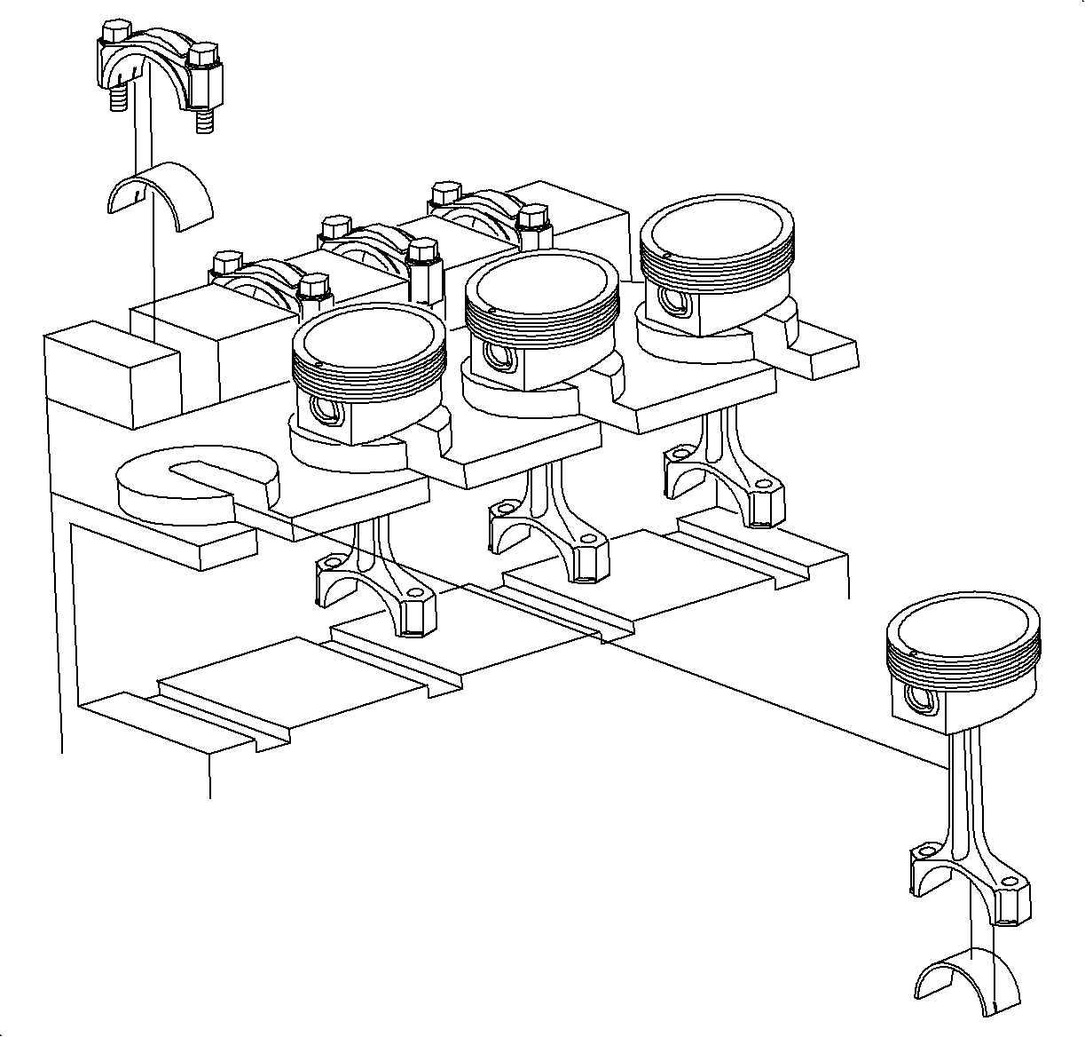
Important: Keep the bearing inserts with the connecting rod and cap. Arrange the piston
and connecting rod assemblies in order.
- Keep the bearing inserts with the connecting rod and cap.
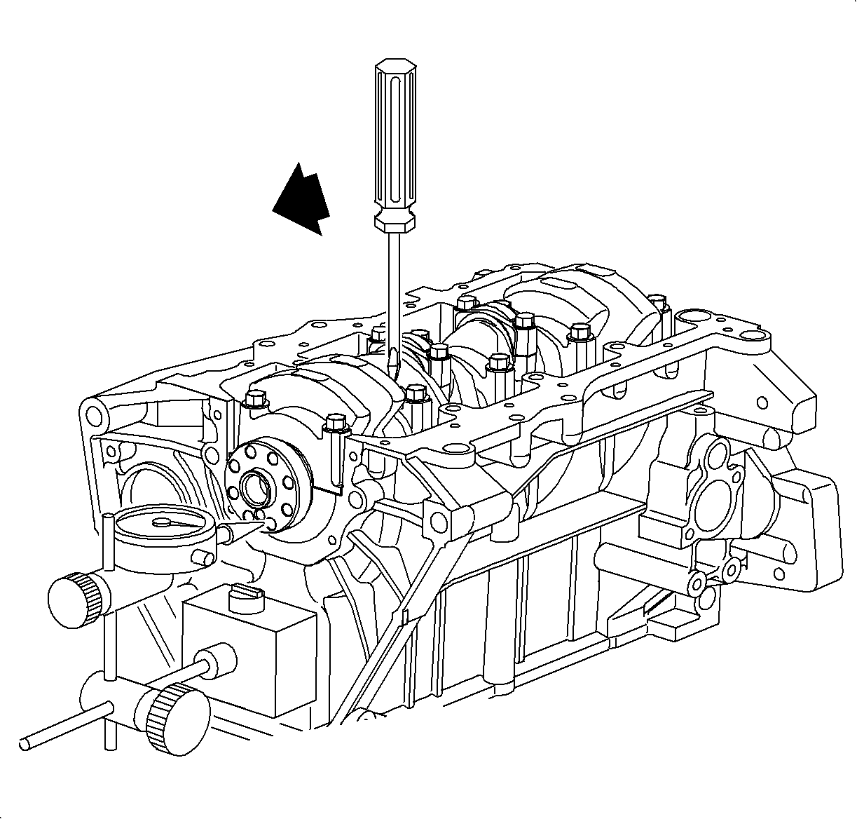
- Check crankshaft thrust clearance:
Using a dial indicator SA9179NE
or equivalent, measure the thrust clearance while prying the crankshaft back
and forth with a screwdriver.
Thrust Clearance
| • | Standard: 0.05-0.2 mm (0.002-0.0089 in) |
| • | Service Limit: 0.25 mm (0.0098 in) max. |
| • | If the clearance is greater than maximum, replace the thrust bearing. |
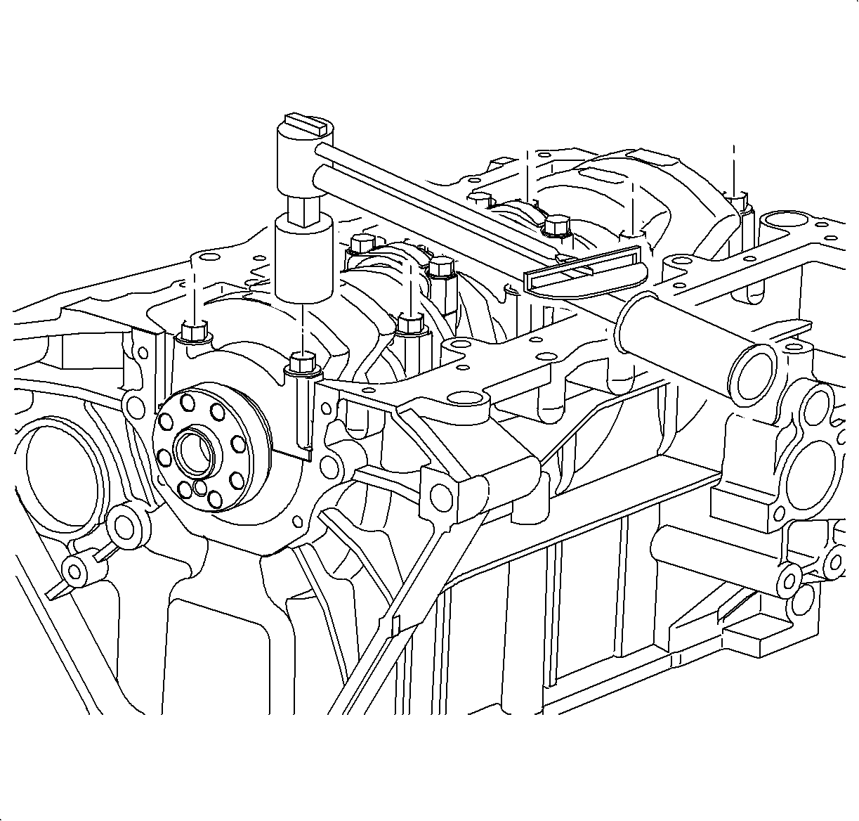
- Uniformly loosen and remove main bearing cap bolts.
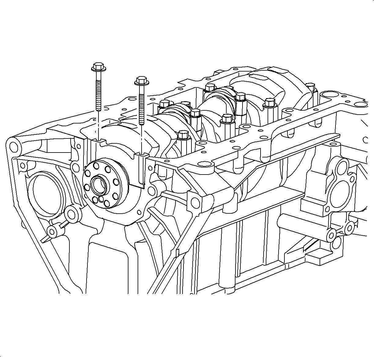
Important: Keep the lower bearing inserted with the cap. Arrange the caps in correct order
according to the number and arrow stamped on each cap.
- Using the main bearing cap bolts, move the cap back and forth, to loosen and
remove the cap and bearing. Bolts can be tapped lightly with a plastic hammer.
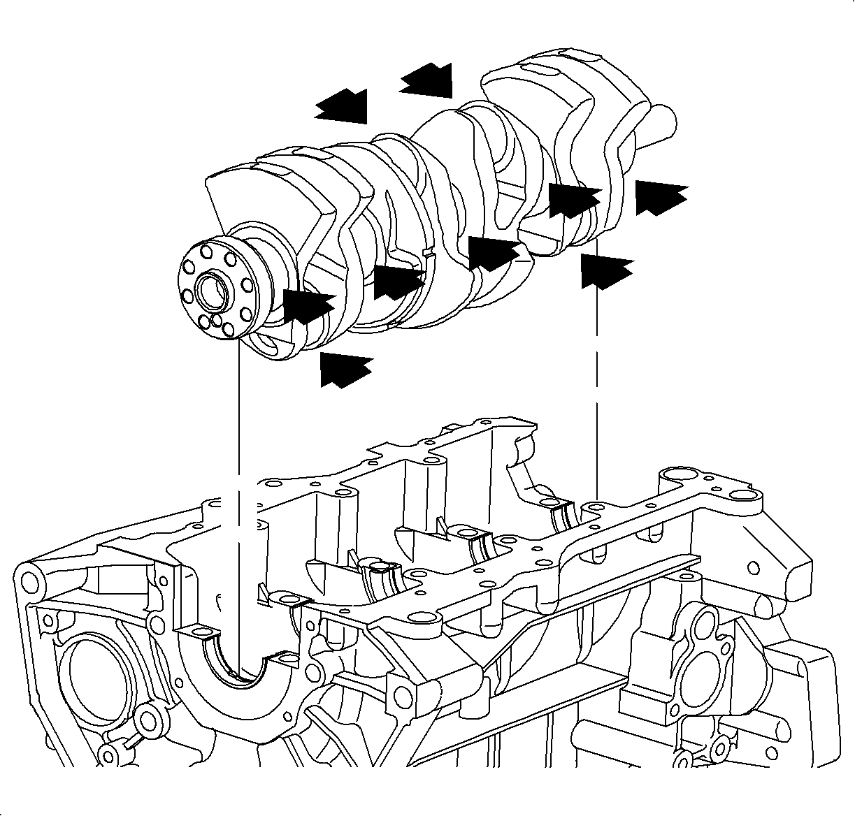
Important: If the journal or bearing is damaged, the bearing will require replacement.
The crankshaft journals can be reground. 0.25 mm (0.01 in) undersized
bearings are available for crankshaft repair.
- Check each journal and bearing for pitting and scratches.
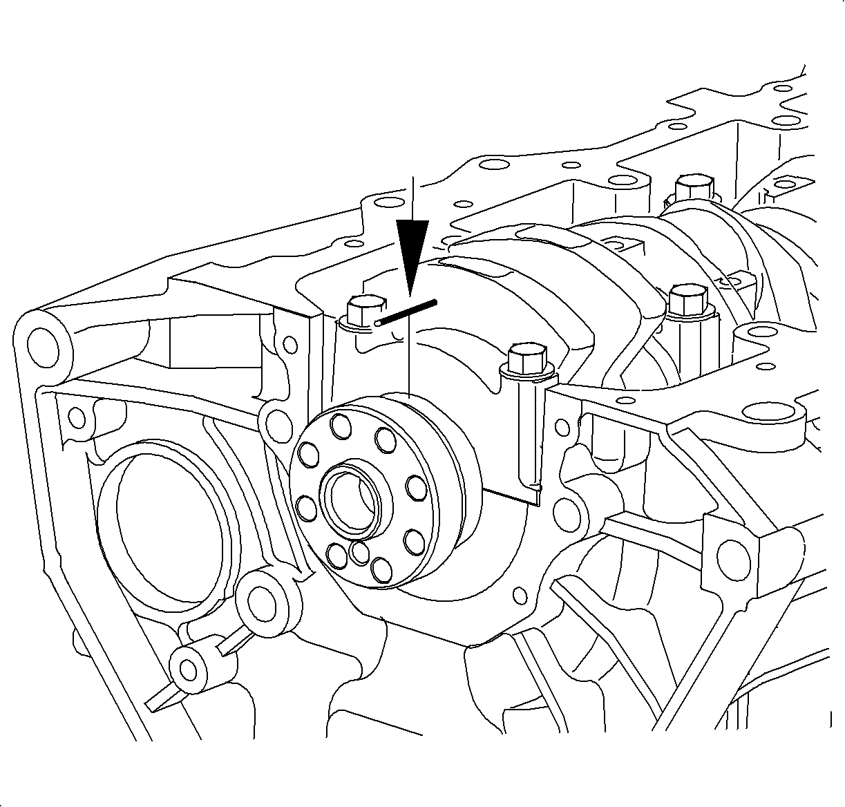
- Lay a strip of Plastigage®, or equivalent across each journal.
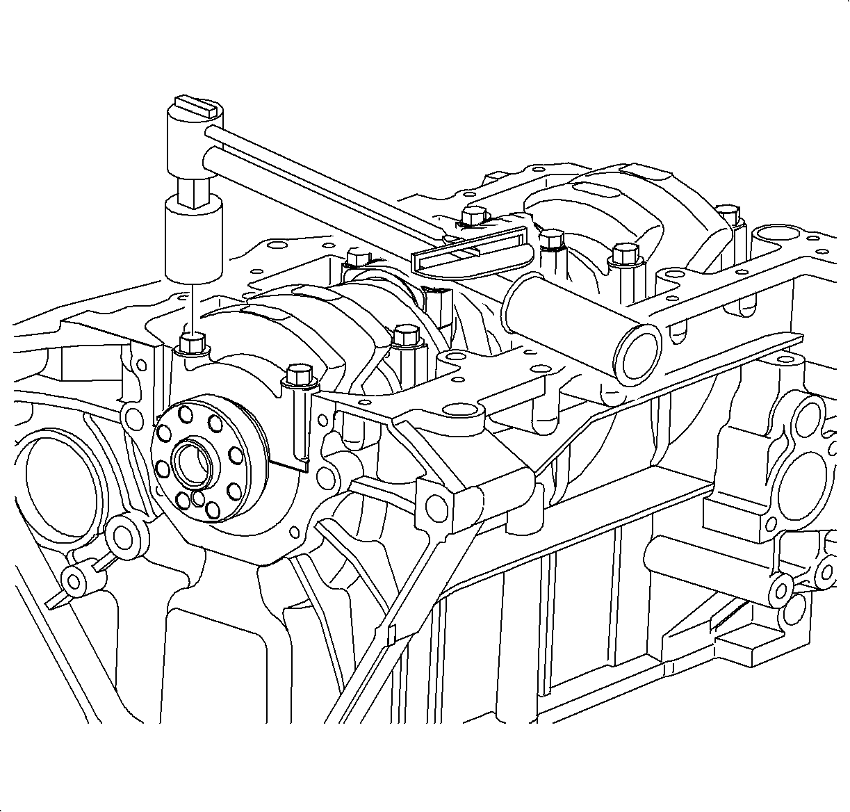
Important: Do not turn the crankshaft.
- Install main bearing caps.
Tighten
Tighten the crankshaft bearing cap-to-block to 50 N·m (37 lb ft).
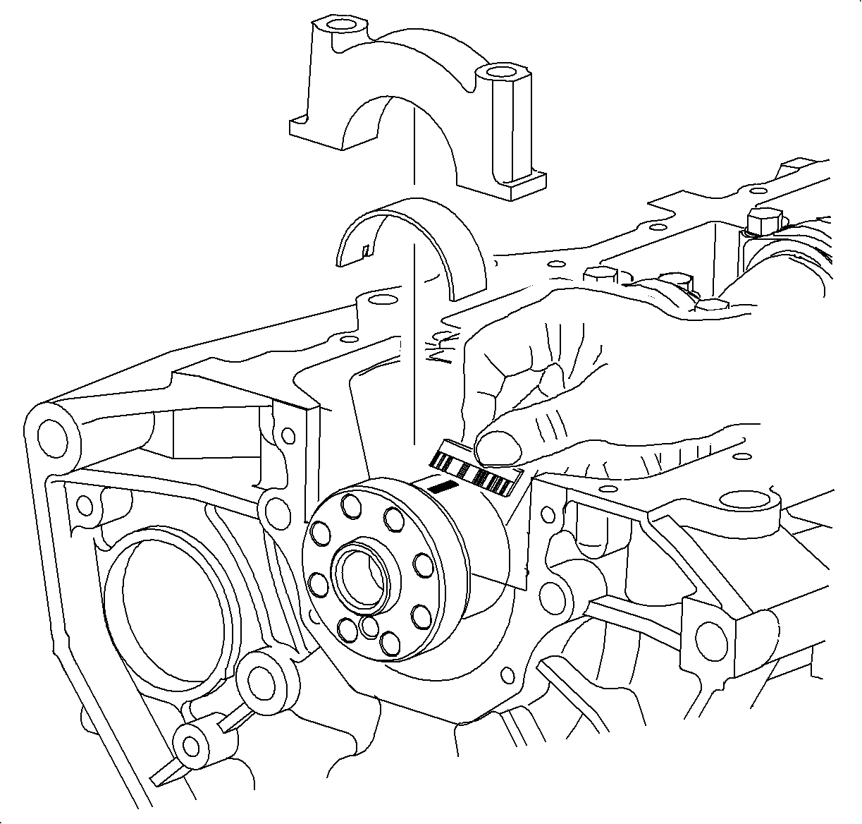
Important: There are three bearing sizes available, standard, 0.012 mm (0.0005 in)
and 0.02 mm (0.001 in) available to adjust for correct main bearing
journal oil clearance. 0.25 mm (0.01 in) undersized bearings are available
for crankshaft repair.
- Remove main bearing caps.
- Measure the Plastigage®, or equivalent at its widest point.
Oil Clearance
| • | Standard: 0.006-0.05 mm (0.0002-0.002 in) No. 1,
2, 3, 4, and 5 |
| • | Service Limit: 0.06 mm (0.0024 in) max. |
| • | If the oil clearance is greater than maximum, replace the bearings. If necessary,
grind the main bearing journals or replace the crankshaft. |
- Completely remove all Plastigage®, or equivalent material.

- Remove the crankshaft:
Important: Arrange caps and bearings in correct order according to the number and arrow
stamped on each cap.
- Lift out crankshaft and remove upper bearings.
