Cylinder Head Assemble SOHC
Tools Required
| • | SA9102E-A Valve Seal Remover/Replacer |
| • | SA9124E Valve Spring Compressor/Remover |
- Clean all parts.
- Oil the valve stems and install the valves stem seals, the valves, the springs, retainers, and the camshaft:
- Use the SA9102E-A to install the valve stem seals.
- Install the valves and the springs.
- Use the SA9124E to install the valve spring caps and the retainers.
- If removed, clean the thrust plate bolts and the camshaft bolt hole threads of any residual sealer, oil, or foreign material. Remove the foreign material with solvent.
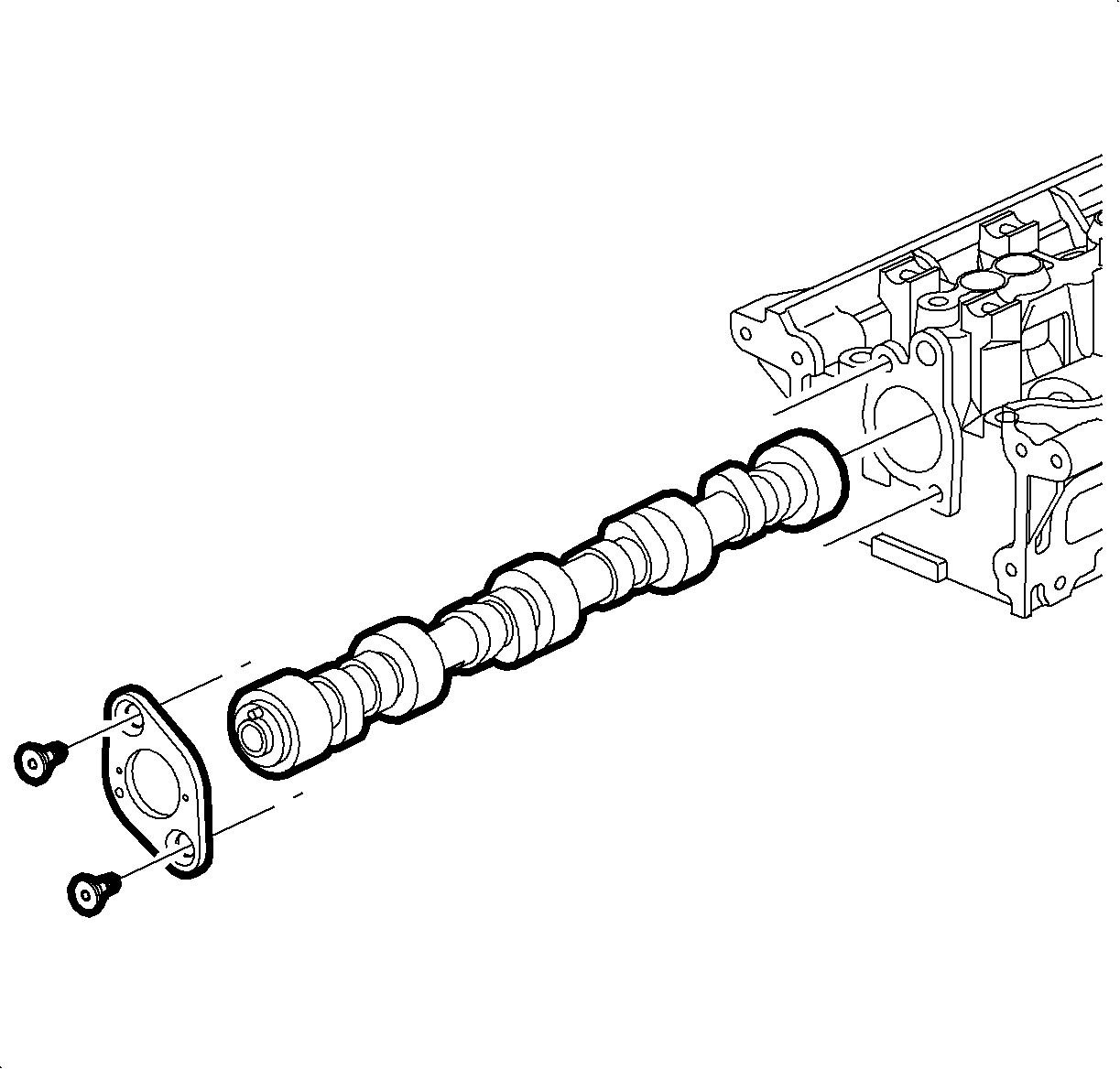
- Oil the camshaft and install it into the cylinder head with the dowel pin at the 12 o'clock position.
- Install the thrust plate and 2 new TORX™ screws.
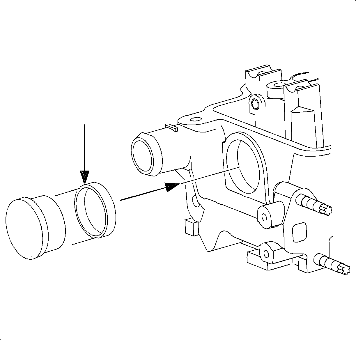
- Coat the rear camshaft cylinder head and 2 oil gallery plugs with Saturn P/N 21485277 LOCTITE® 242 or equivalent, and install it using a standard bushing driver, if removed. Refer to the General Description page of this section for plug locations.
- Oil the hydraulic lifters with clean engine oil and install them in the cylinder head. Rotate the lifters until the flat sides are parallel to the intake and exhaust manifold flanges.
- Install the lifter guide plates.
- Oil the rocker arm shaft and install the rocker arms on both shafts.
- Snap 1 end of each lifter guide plate retaining spring onto the rocker arm shaft between the No 1-2 and the No 3-4 cylinder rocker arms.
- Install the rocker arm and shaft assembly on the cylinder head. Ensure the rocker arm tangs, slots, are squarely seated on the hydraulic lifter plunger. The retaining spring must be positioned in the guide plate slot.
- Tighten down the 5 rocker arm shaft bolts uniformly.
- Install the second rocker arm assembly. Snap the lifter guide plate retaining spring onto the shaft. Ensure the rocker tangs, slots, are squarely seated on the hydraulic lifter plunger as the assembly is installed.
- Check all lifters, guide plates, guide plate retaining springs and rocker arm tangs, slots, for proper installation.
- Install the intake manifold using a new intake manifold gasket.
- Tighten the bolts in the following sequence:
- Install the exhaust manifold using a new exhaust manifold gasket.
- Install the rear engine support, lift, bracket, if removed.
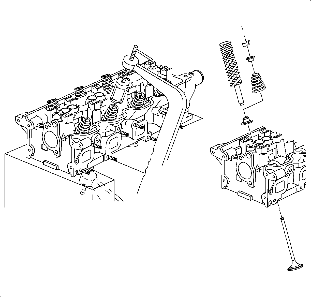
Important: After each valve is installed, oil the valve stem and guide before installing the seal. If a valve stem seal is removed, it must be discarded.
Notice: Do not depress the spring cap too far as it will cause valve stem seal and valve stem damage.
Notice: The dowel pin end of the camshaft must be located at the 12 o'clock position during installation to prevent valve and piston damage.
Tighten
Tighten the camshaft thrust bearing-to-head (L24)
to 25 N·m (19 lbs ft)
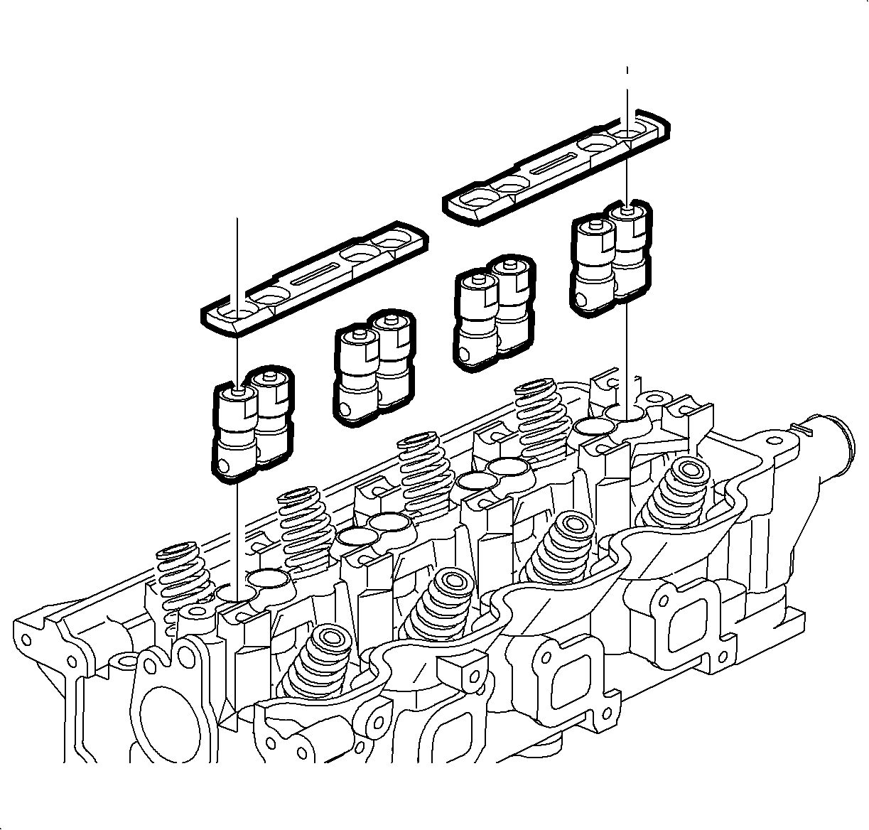
Important: Ensure the guide plates are properly seated, retaining spring slot upward on the cylinder head and all lifters fit squarely in the guide plate.
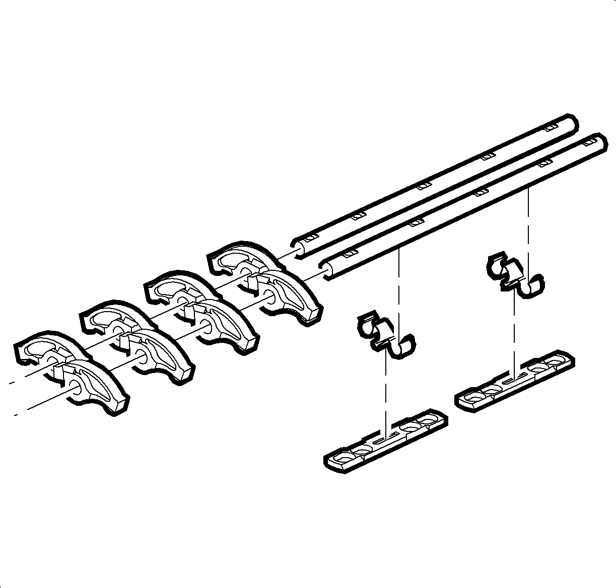
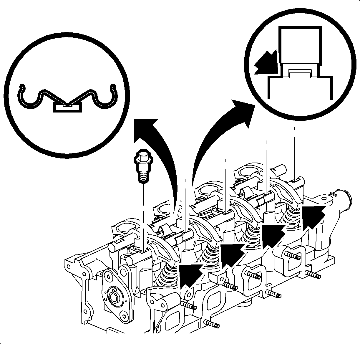
Notice: Rocker arm tangs (slots) must be properly seated prior to tightening the rocker arm shaft bolts or valve and piston damage will occur.
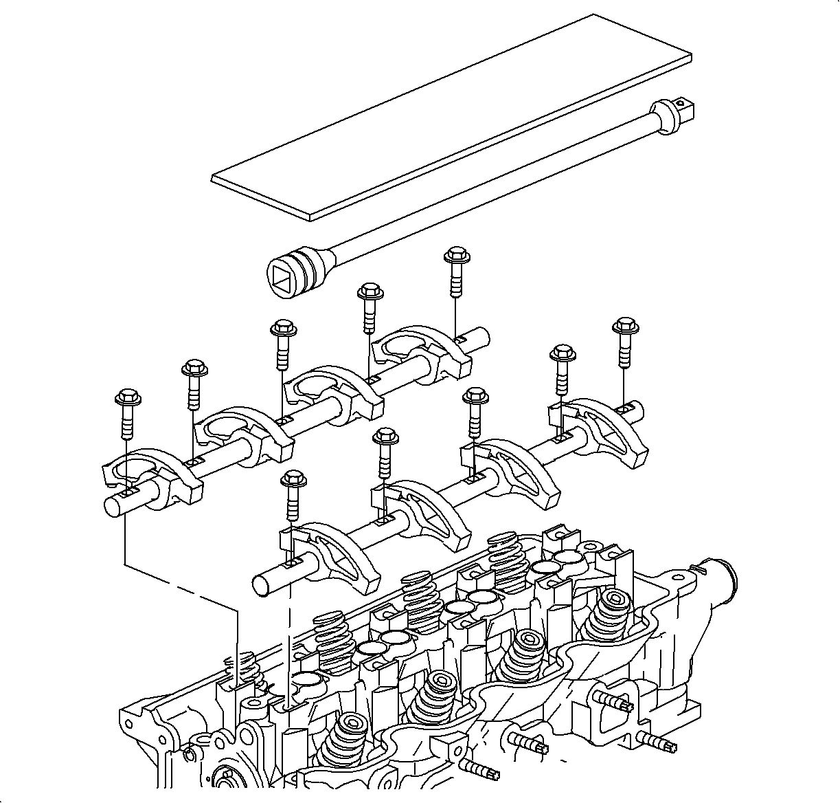
Notice: The rocker arm assembly must be properly assembled to prevent engine damage.
Important: A flat piece of cardboard (2 in x 14 in) or extension bar can be placed on top of the rocker arm assemblies, both shafts with all rocker arms during installation for alignment of rocker arms on valves and hydraulic lifters.
Tighten
Tighten the rocker arm shaft-to-head to 25 N·m
(19 lb ft).
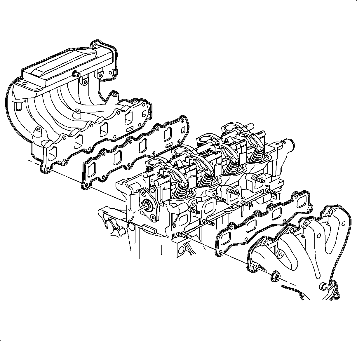
Important: Ensure all gasket surfaces are clean when installing manifolds and cylinder head assembly to prevent oil leakage.
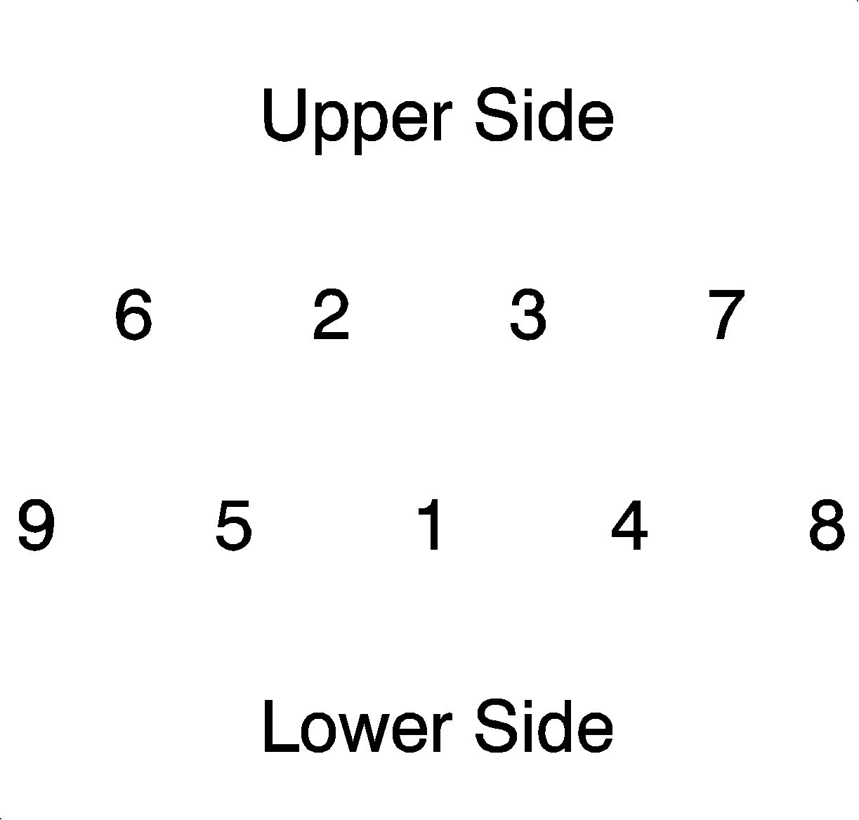
Tighten
Tighten the intake manifold-to-head (L24) to 30 N·m
(22 lb ft).
Important: Install the gasket with the smooth side toward the exhaust manifold. In sequence, torque the exhaust manifold attachment nuts. The center fasteners may lose torque when the outer fasteners are tightened. Therefore, torque all fasteners a second time.
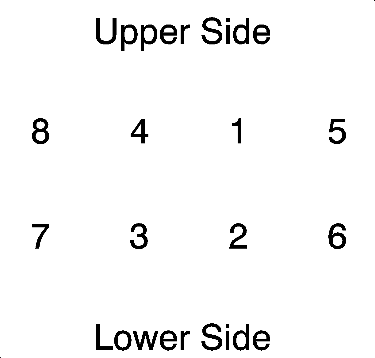
Tighten
Tighten the exhaust manifold-to-head (L24) to 22 N·m
(16 lb ft).
Cylinder Head Assemble DOHC
Tools Required
SA9102E-A Valve Seal Remover
- Clean all parts. Coat the 3 oil gallery plugs with Saturn P/N 21485277 Loctite 242® Threadlocker, or equivalent, and install them using a standard driver, if removed.
- Install new valve stem seals using the SA9102E-A . Do not oil the seal's inner diameter where it contacts the guide.
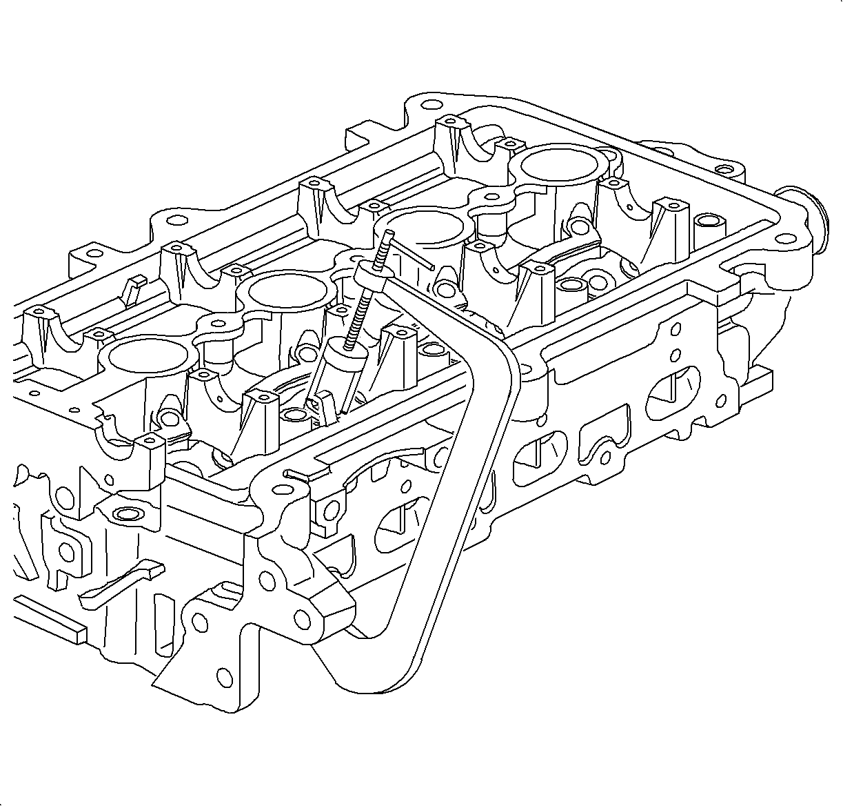
- Oil the valve stems and install the valves, springs, caps, and retainers.
- Fill the hydraulic lash adjusters with clean engine oil using an oil squirt can, lubricate the lash adjuster body and install them in their proper locations.
- Assemble rocker arms over lash adjusters and valve stems.
- Oil the camshaft (lobes and journals) and install each in the cylinder head with the dowel pin at the 12 o'clock position.
- Install all the bearing caps on each camshaft with the arrows pointed toward the camshaft sprockets. The camshaft bearing caps are numbered and have an I -- for intake side and an E -- for exhaust manifold side stamped on them. Tighten the caps down uniformly.
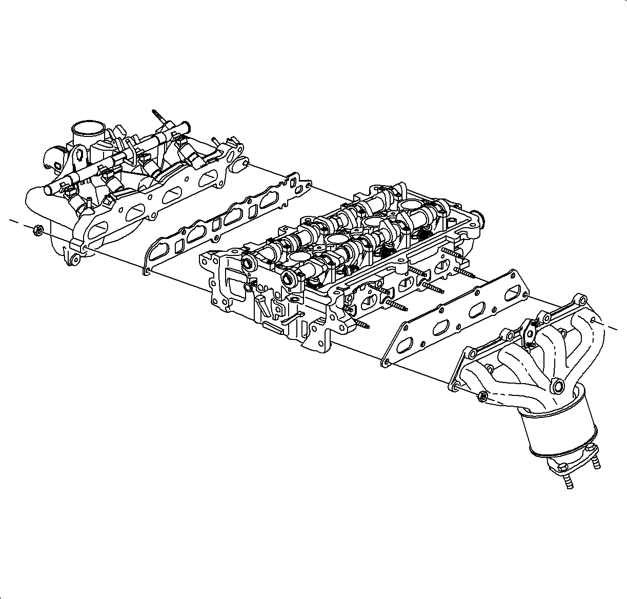
- Install the intake manifold.
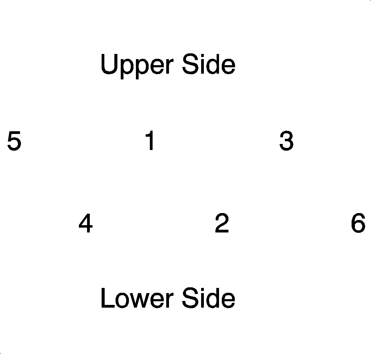
- Tighten the nuts in the following sequence:
- Install the exhaust manifold using a new exhaust manifold gasket.
- Torque the exhaust manifold attachment nuts in the following sequence:
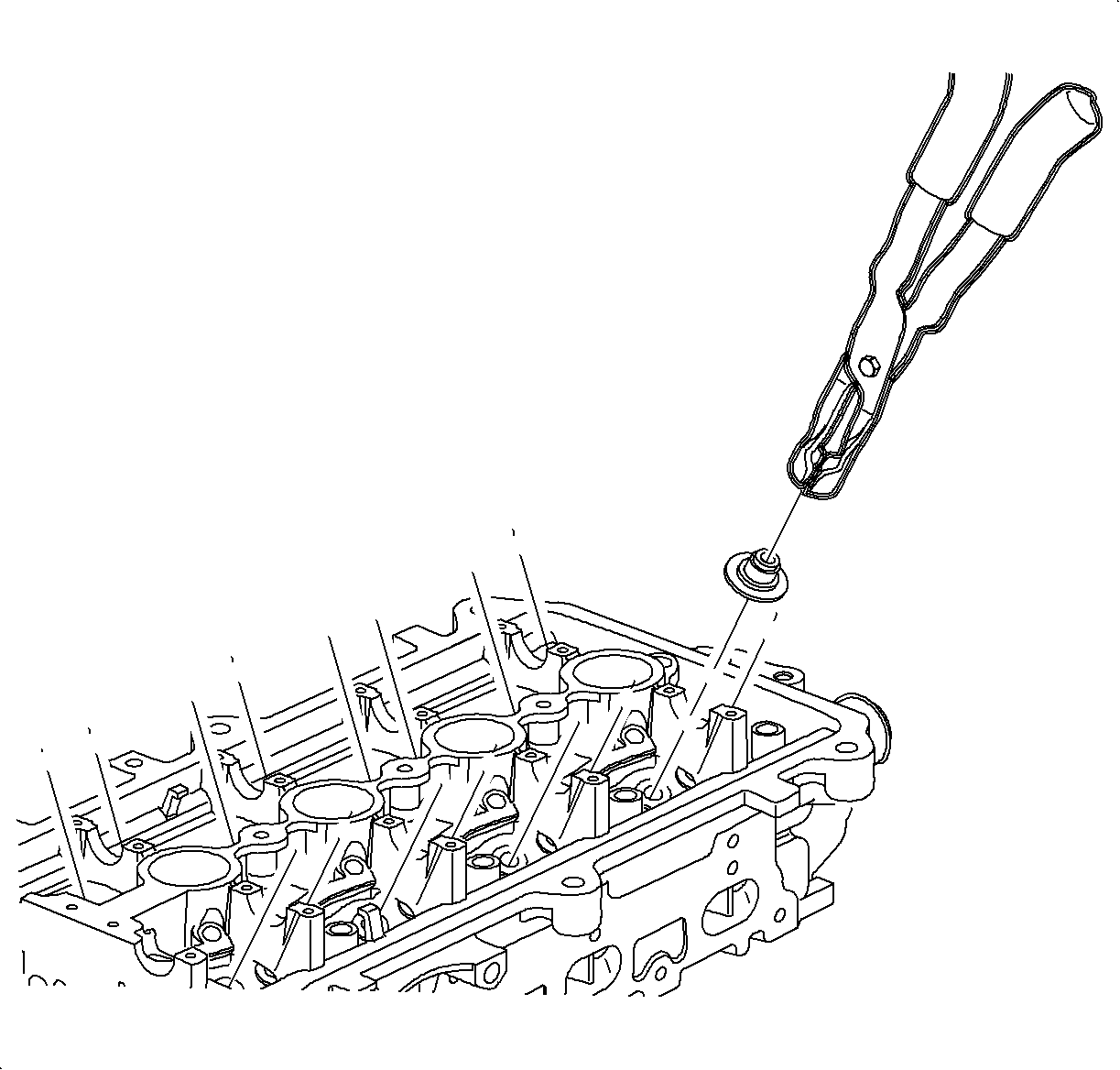
Notice: Do not depress the spring cap too far as it will cause valve stem seal and valve stem damage.
Important: After each valve is installed, oil the valve guide with clean engine oil and stem before installing the valve stem seal. If a valve stem seal is removed, it must be discarded.
Notice: The dowel pin in each camshaft must be located at the 12 o'clock position during installation to prevent valve and piston damage.
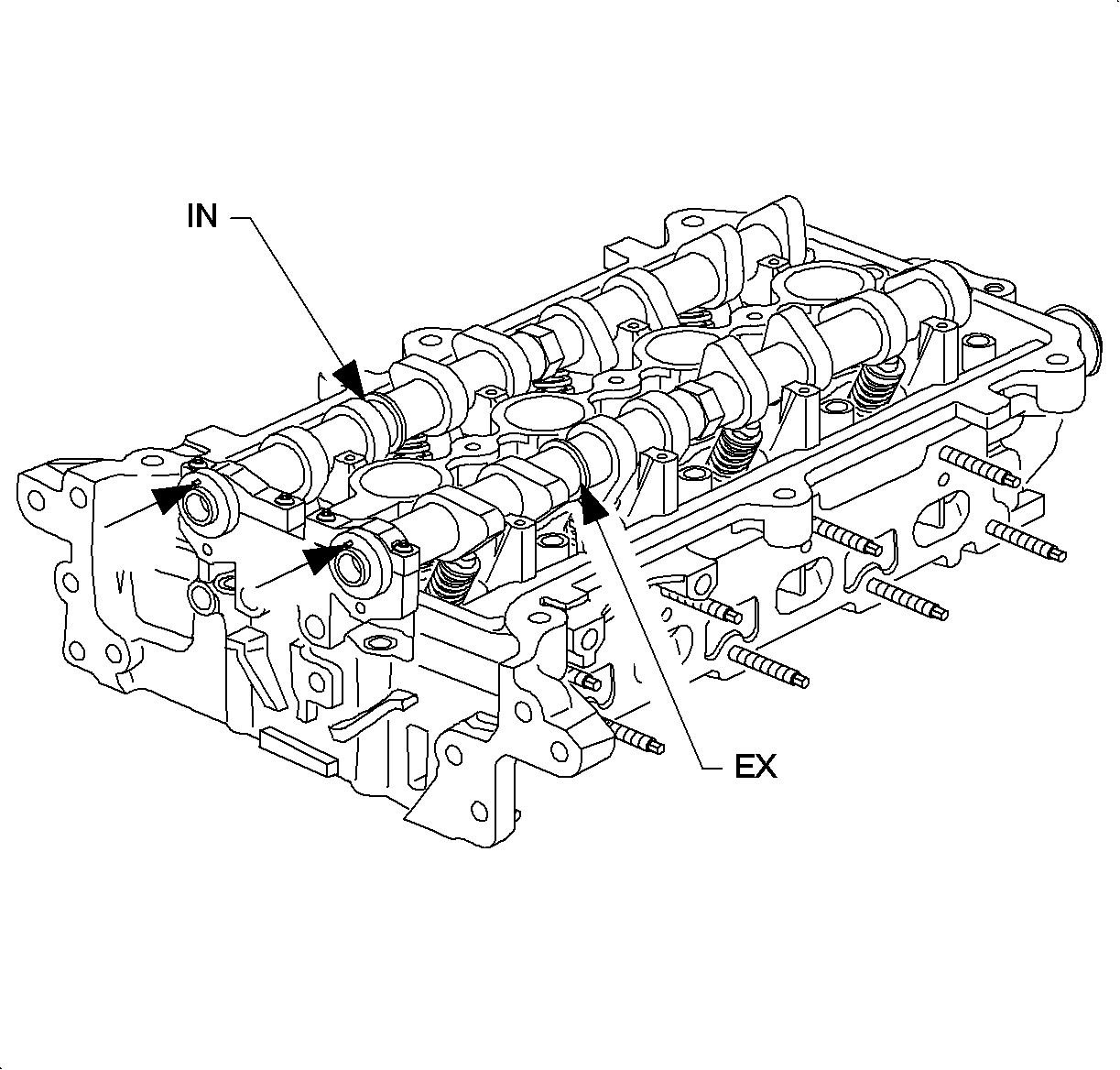
Important: Camshafts are identified IN, intake manifold side of engine and EX, exhaust
side of engine. If the camshafts are installed at the wrong location, the following
will occur:
• The oil baffles in the cam cover will interfere with the camshaft and
the cam cover will not assemble properly. Noise will be evident upon engine operation. • DTC P0172 (System Rich) is likely to set. • Poor engine performance at throttle tip-in will be evident.
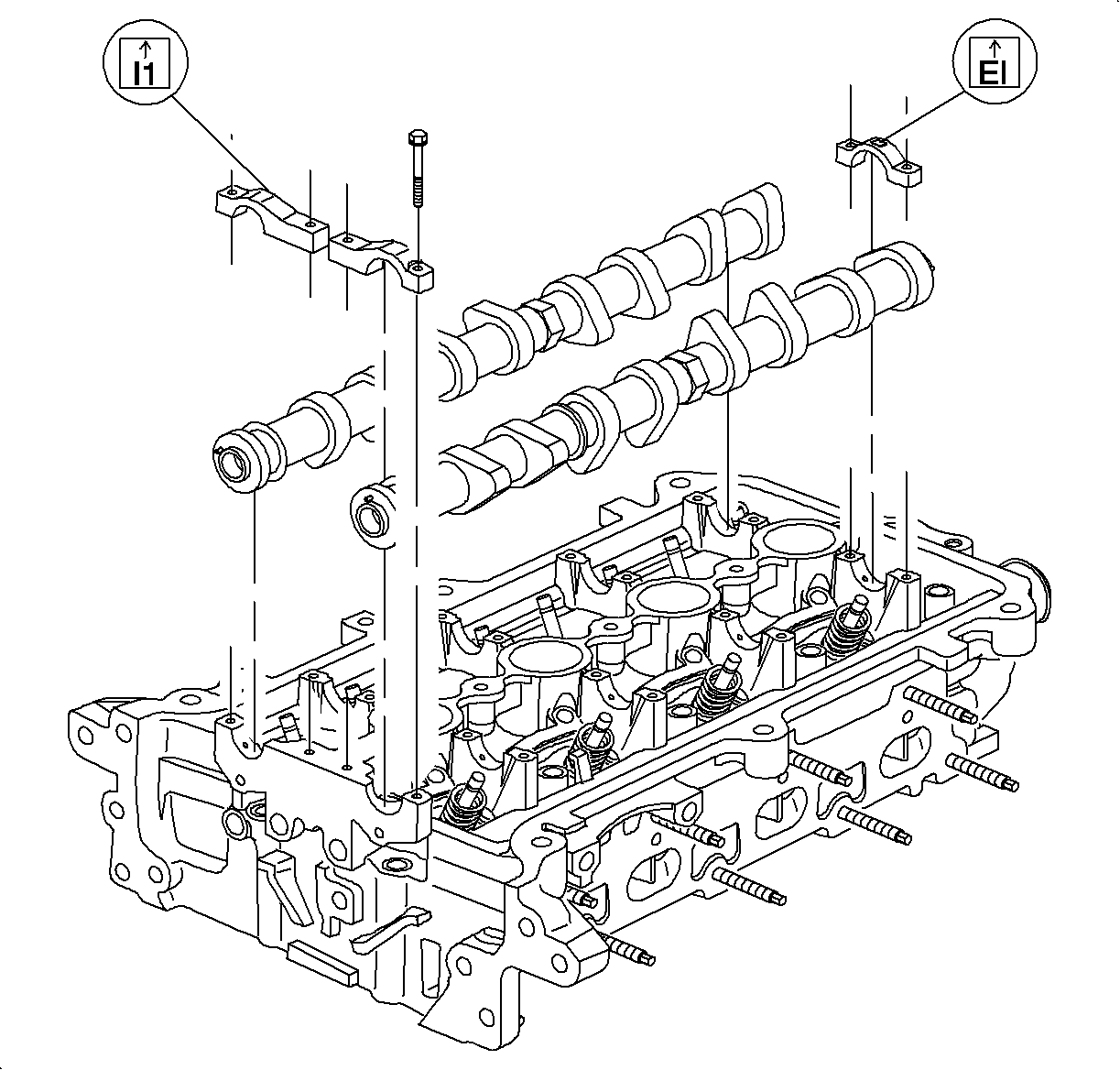
Notice: Fully tightening down one bearing cap at a time will break the camshaft and damage the cylinder head cam bearings surfaces or damage the cap bolt threads.
Important: The forward bearing caps are used to control thrust. The camshafts must be positioned fully forward prior to their installation.
Tighten
Tighten the camshaft bearing cap-to-head (LL0) to 14 N·m (10 lb ft).
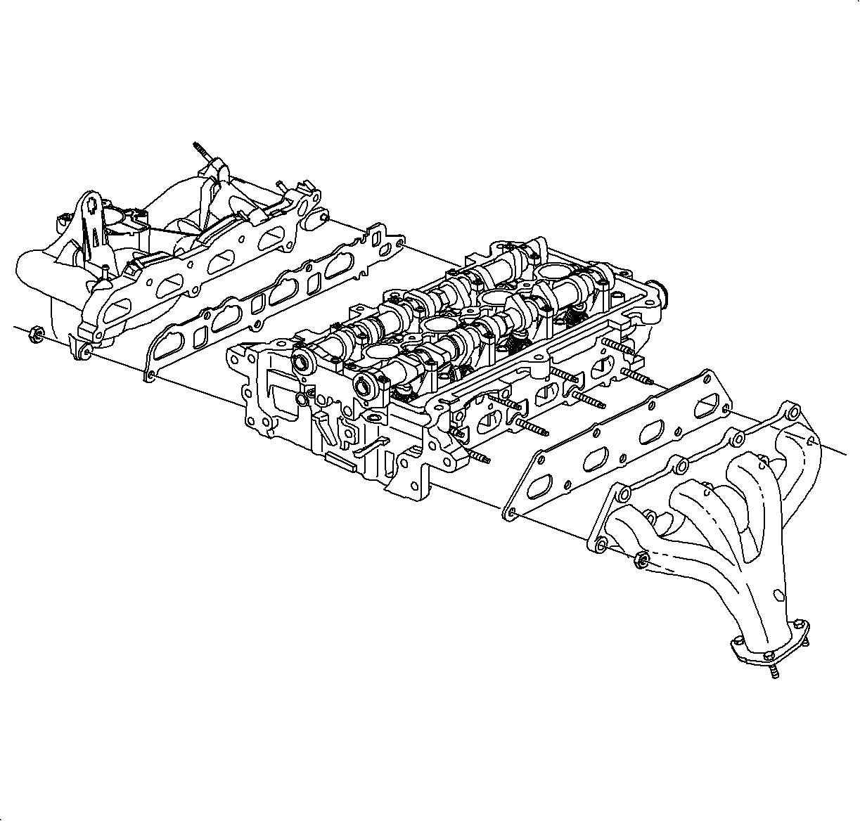
Notice: Make sure all gasket surfaces are clean when installing manifolds and the cylinder head assembly. Inspect the intake manifold gasket for nicks, cuts, or swelling. Replace the intake manifold gasket if any of these conditions are found.
Tighten
Tighten the exhaust manifold-to-head (LL0) to 18 N·m (13 lb ft).
Important: In sequence, torque the exhaust manifold attachment nuts. The center fasteners may lose torque when the outer fasteners are tightened. Therefore, re-torque all fasteners a second time.

