Caution: Safety precautions must be followed when handling a deployed inflator module (air bag). After deployment, the inflator module (air bag) surface may contain a small amount of sodium hydroxide, a by-product of the deployment reaction, that is irritating to the skin and eyes. Most of the powder on the inflator module (air bag) is harmless. as a precaution, wear gloves and safety glasses when handling a deployed inflator module (air bag), and wash your hands with mild soap and water afterwards.
Caution: When you are carrying an undeployed inflator module:
• Do not carry the inflator module by the wires or connector on
the inflator module • Make sure the bag opening points away from you
Important: In the event deployment has occurred, refer to Repairs and Inspections Required After a Collision .
Removal Procedure
- Disable the SIR System. Refer to Disabling the SIR System .
- Remove the screws on underside of the upper I/P trim panel, passenger side.
- Disengage the clips at locations by grasping the edges of the upper I/P trim panel and lifting up.
- Disengage the hook and loop the fasteners at rear of the upper I/P trim panel by reaching under and panel and lifting straight up.
- Raise the upper I/P trim panel enough to clear the VIN plate.
- Remove the right I/P endcap assembly:
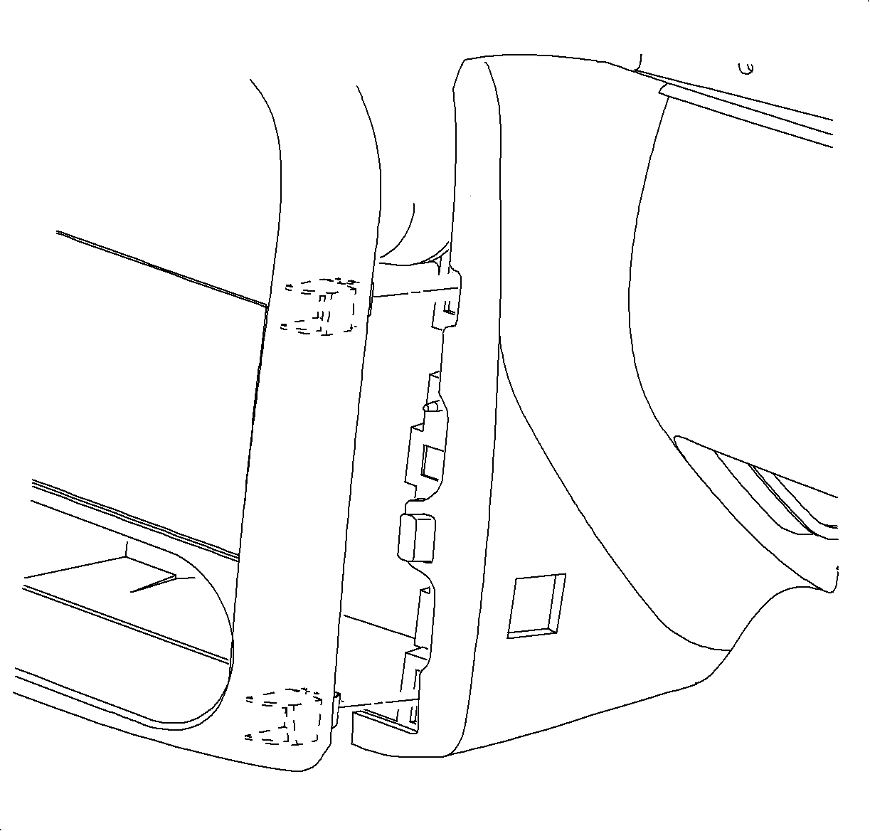
- Separate the two clips from the clip locations attaching the I/P bezel to the retainer assembly. Access is necessary to move the inflator module door from the locator pin.
- Remove the screws attaching the inflator module door to the retainer assembly.
- Remove the air bag wire harness from the rosebud loop.
- Remove the glove compartment front retainers by turning counter-clockwise. Allow the glove compartment bottom to hang on the rear pins.
- Remove inflator module to I/P brace bolts.
- Grasp the inflator module and pull gently while releasing the plastic tabs at each end.
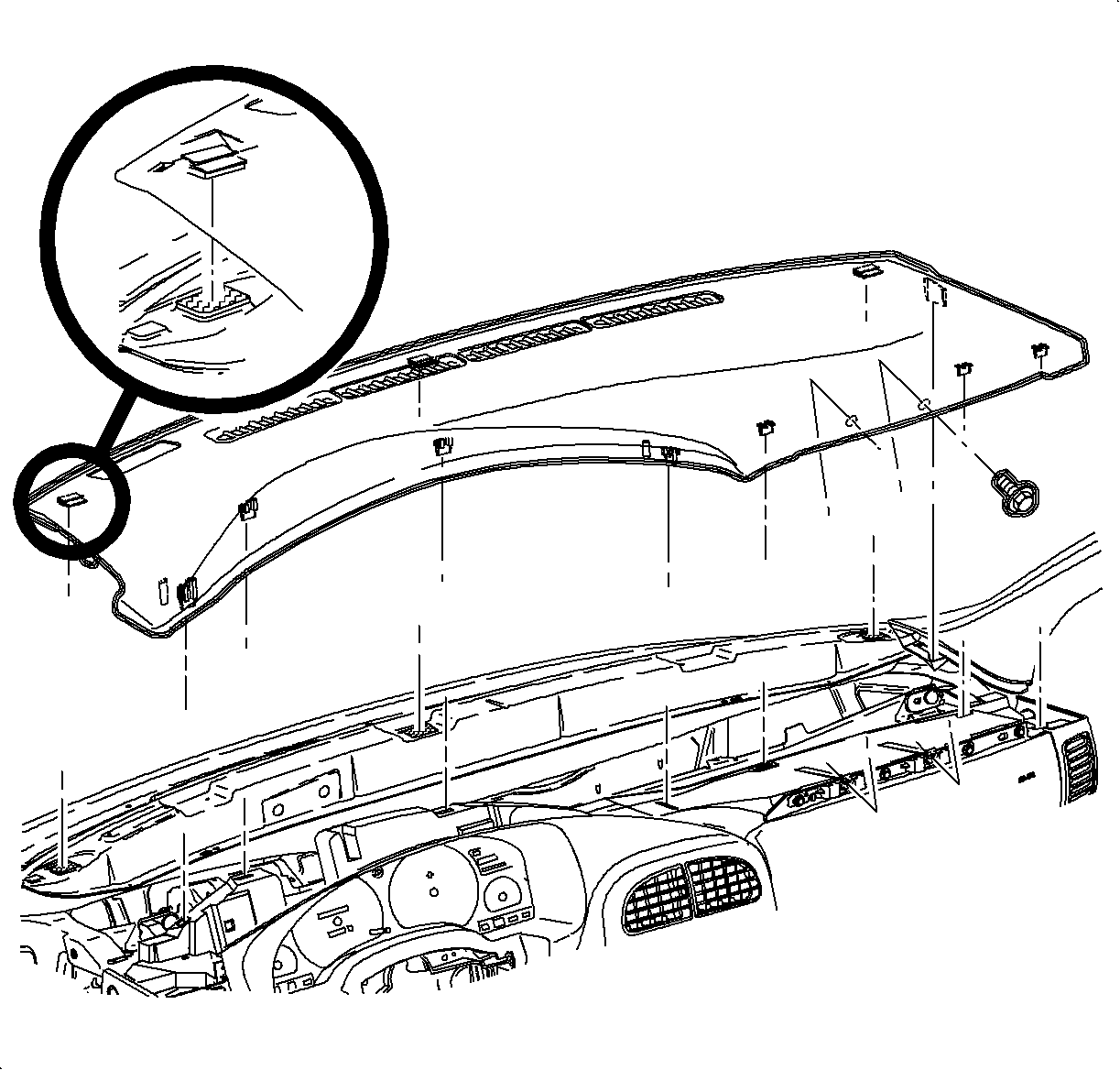
Notice: Be careful not to damage the VIN plate when removing or replacing the upper trim panel.
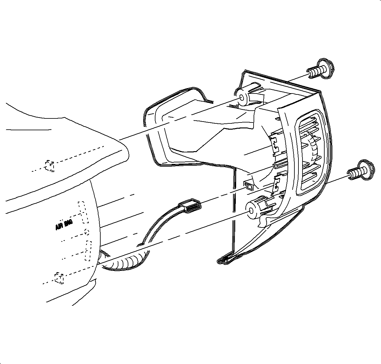
| 6.1. | Remove the screws. |
| 6.2. | Carefully disengage the clips at the I/P retainer assembly locations. Use of a blunt tool will aid in disengaging the clips. |
| 6.3. | Maneuver the assemblies past inner I/P retainer assembly and weather-strips. |
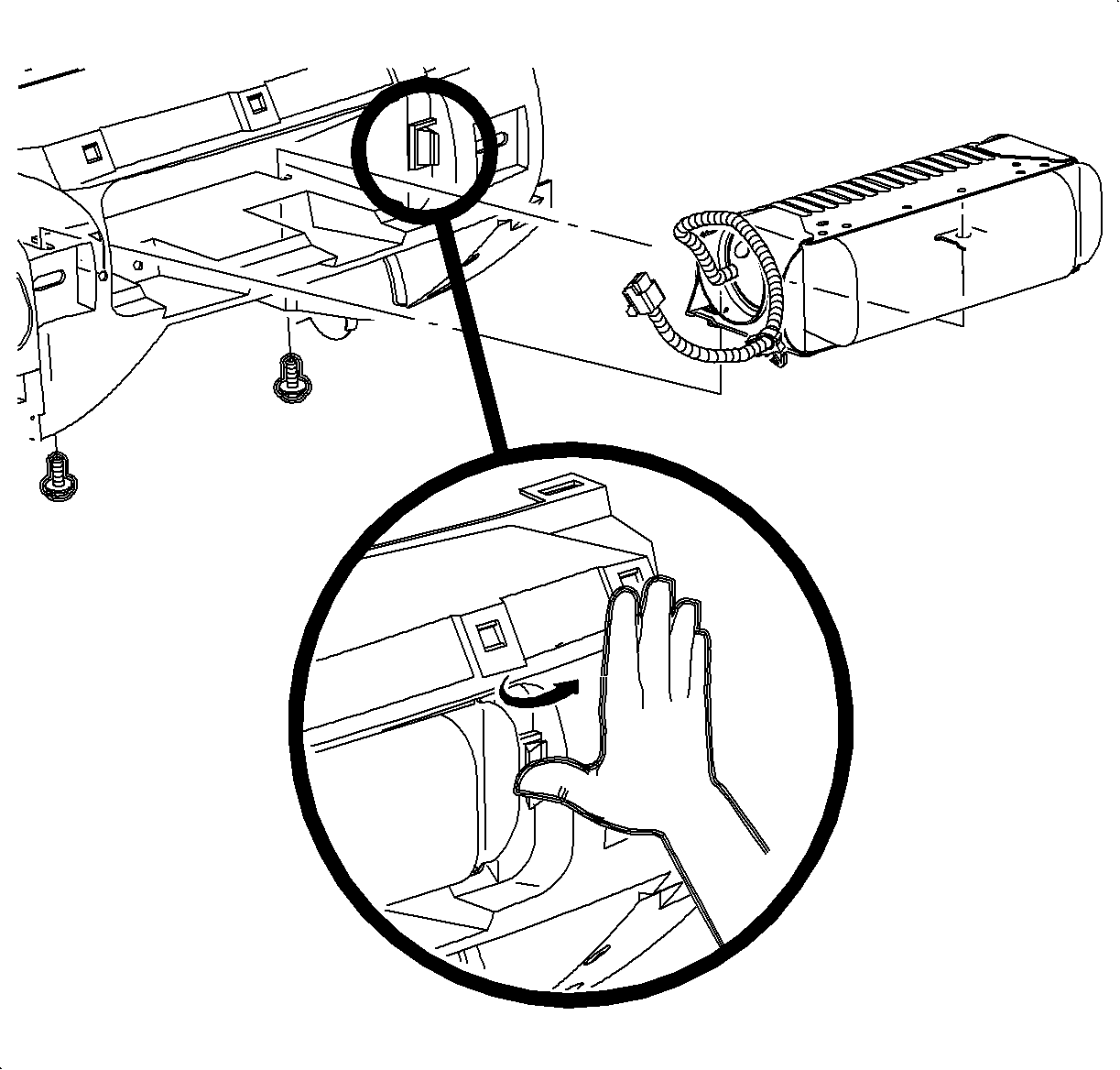
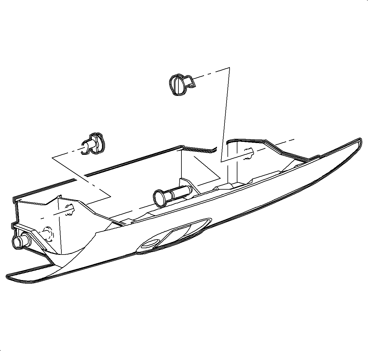

Important: Access the right-side bolt through the hole in the top of the glove compartment. Access the left-side bolt through the opening at the top left end of glove compartment.
Installation Procedure
- Guide the inflator module wire harness through the opening and route over foam I/P insulator.
- Insert the inflator module into the opening until plastic tabs lock.
- Install the inflator module to the I/P brace bolts.
- Insert the glove compartment front retainers and rotate clockwise to secure.
- Secure the inflator module wire harness with the rosebud loop.
- Position the inflator module door to the retainer assembly and install screws.
- Install the two clips into the clip location attaching the I/P bezel to the retainer assembly.
- Install the right I/P endcap assembly:
- Position the upper I/P trim panel on the retainer assembly.
- Align the tabs on the sides of the upper I/P trim panel with the openings in the windshield garnish molding.
- Snap in the clips at the clip locations.
- Install (2) screws on underside of upper I/P trim panel on passenger's side of vehicle.
- Close the glove compartment door.
- Enable the SIR system. Refer to Enabling the SIR System .
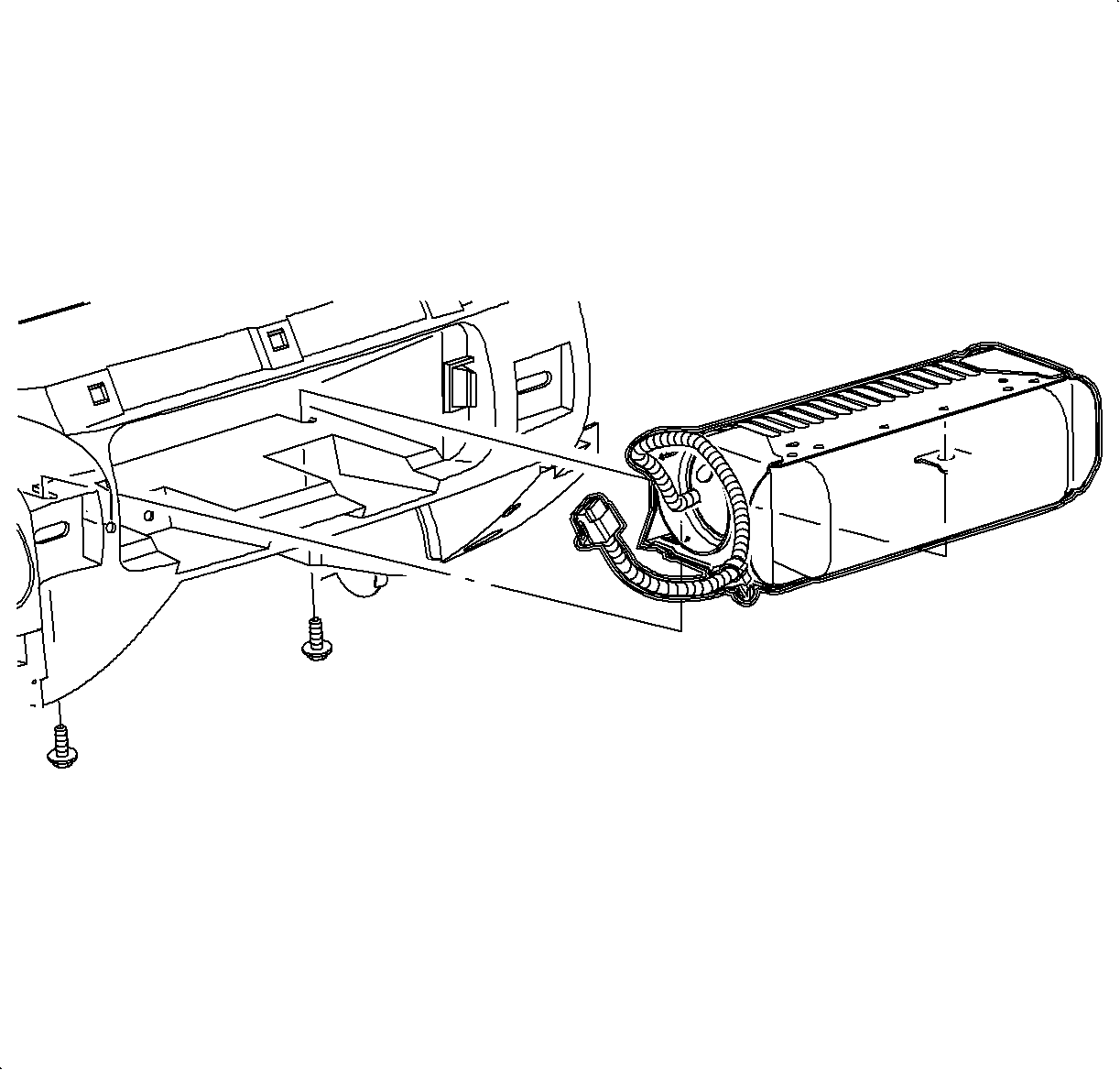
Notice: Refer to Fastener Notice in the Preface section.
Tighten
Tighten the passenger inflator module (air bag) bolts to 10 N·m
(89 lb in).


Tighten
Tighten the passenger inflator module cover fasteners to 2.2 N·m
(20 lb in).

| 8.1. | Maneuver the assembly past inner I/P retainer assembly and weather-strips. |
| 8.2. | Snap clips into the I/P retainer assembly locations. |
| 8.3. | Install the screws. |
Tighten
Tighten the right I/P end cap fasteners to 2.2 N·m (20 lb in).

Notice: Be careful not to damage the VIN plate when removing or replacing the upper trim panel.
Important: Be sure the upper I/P trim panel seal is correctly seated on the forward edge before installing the upper trim panel.
Tighten
Tighten the upper I/P trim panel fasteners to 6 N·m (53 lb in).
