Removal Procedure

- Disable the SIR system. Refer to
Disabling the SIR System
in SIR.
Notice: Be careful not to damage the VIN plate when removing or replacing the upper
trim panel.
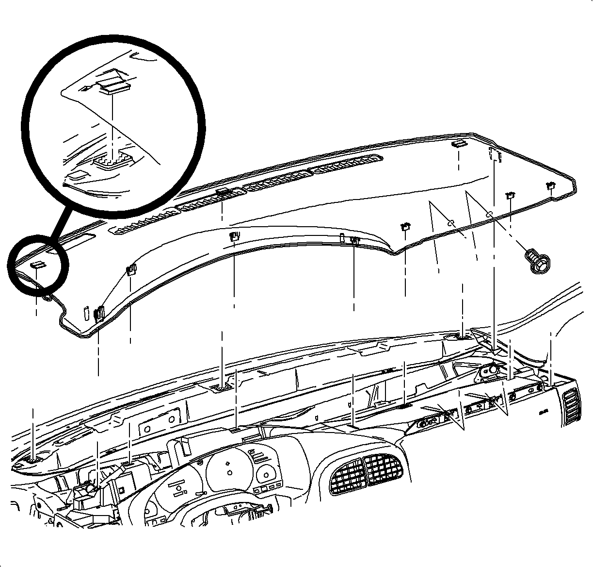
- Remove the instrument panel upper trim:
| 2.1. | Remove the screws located under the upper trim panel on the passenger's
side of the vehicle. |
| 2.2. | Disengage the clips at locations by grasping the edges of the upper trim
panel and lifting up. |
| 2.3. | Disengage the hook-and-loop fastener attachments at the rear of the upper
trim panel by reaching under the panel and lifting straight up. |
| 2.4. | Raise the upper trim panel enough to clear the VIN plate. |

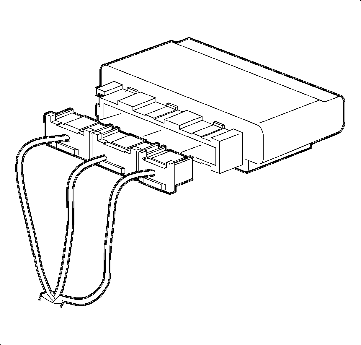
- Remove all BCM mating connectors from the BCM.

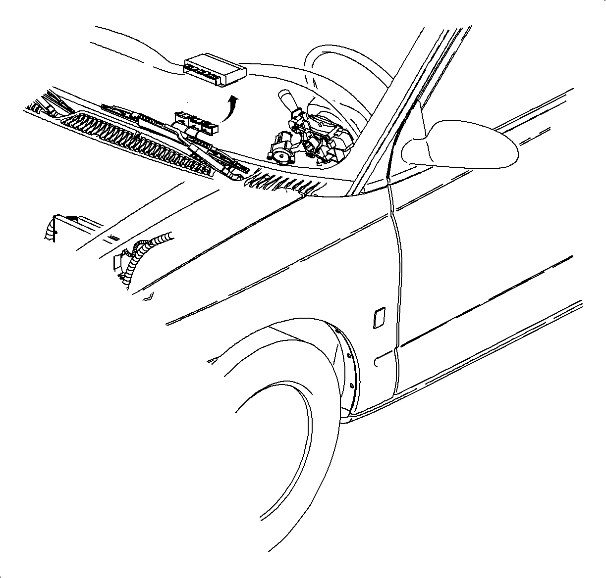
- Grasp the BCM under the connector side and pull upward and back. Rock the module
from side to side to disengage the adhesive material.
- Pull the BCM straight up and out, grasping the adhesive material with
your free hand and tearing away from the cross-car beam to free the BCM.
- Using your fingers, grasp and peel off the remaining bulk of adhesive
material from the cross-car beam surface.
Installation Procedure

Notice: Excessive amounts of old adhesive material will not allow replacement BCM to
be installed properly on cross-car beam.
- Inspect the cross-car beam BCM mounting surface to ensure it is
free of excessive adhesive material.
- Remove the adhesive material backing paper from the replacement BCM.

Important: Alignment tabs must be engaged before contact is made between adhesive and the
BCM mounting surface.
- Align and engage the cross-car beam location with the BCM alignment tabs located
under the BCM connector body.
- Firmly press the BCM into place on the cross-car beam.
- Reinstall the BCM connectors making sure the connector locking tabs are
fully engaged
- Install the upper trim panel.
| 6.1. | Ensure the hook-and-loop fasteners on the upper trim panel are correctly
inserted. |
| 6.2. | Position the upper trim panel on the retainer assembly. |
| 6.3. | Align the tabs on the sides of the upper trim panel with the openings
in the windshield garnish molding. |
| 6.4. | Align the clips and clip location and firmly snap into place. |
| 6.5. | Install the screws on the underside of the upper trim panel on the passenger's
side of the vehicle. |
Tighten
Tighten the upper trim panel-to-I/P screw to 6 N·m (53 lb
in).
- Enable the SIR system. Refer to
Enabling the SIR System
in SIR.


