For 1990-2009 cars only
Removal Procedure
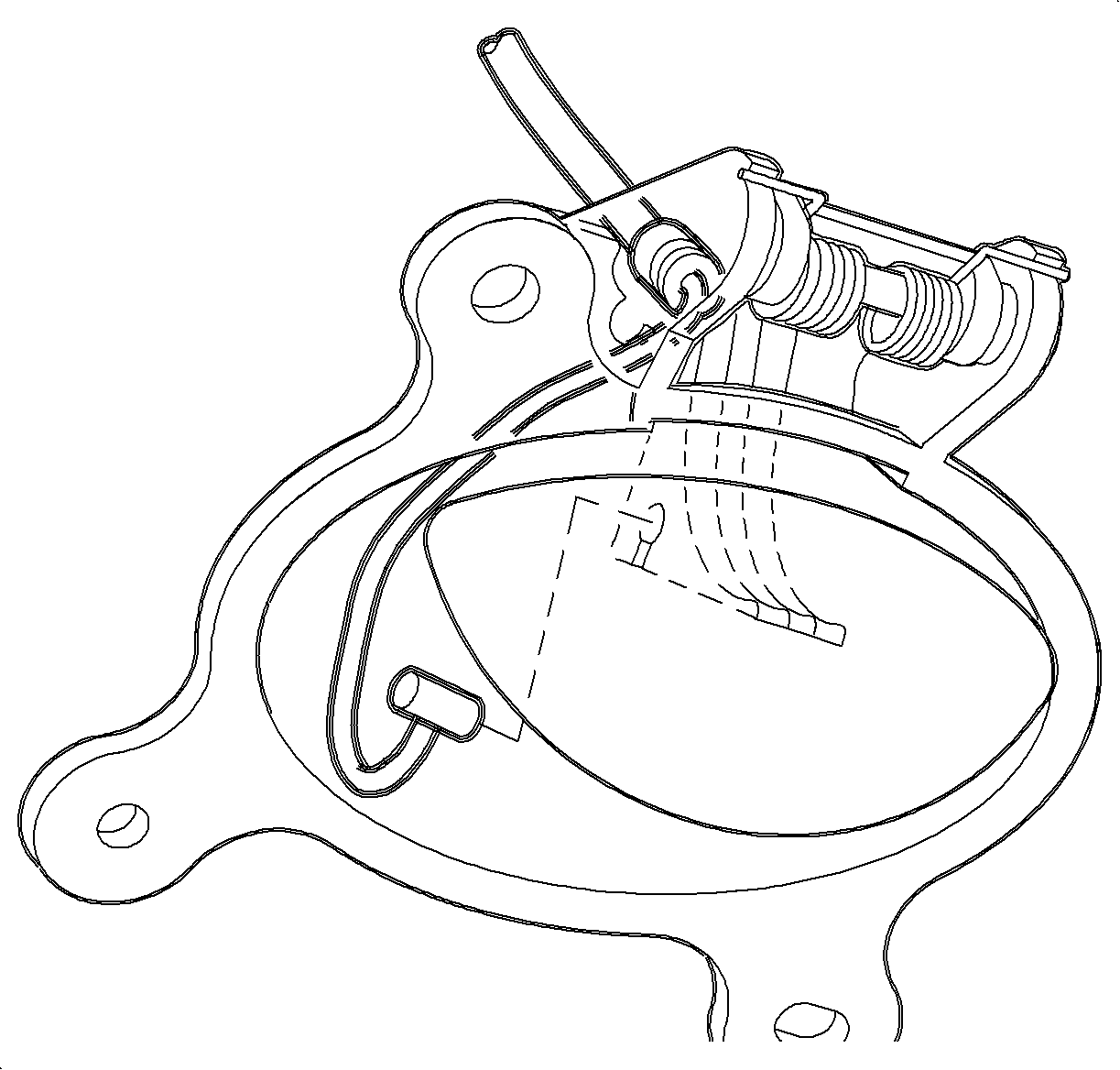
- Disable the SIR system. Refer to Disabling the SIR System in SIR
- Remove the SIR coil assembly. Refer to Inflatable Restraint Steering Wheel Module Coil Replacement in SIR.
- Pull the steering column filler panel assembly forward and set down.
- Disconnect the cable from the filler panel. Pull the hood release handle forward. Feed the cable under the hood release handle and slide the pin out. Remove the steering column filler panel.
- Remove the connector position assurance (CPA) retainer and disconnect the connectors from the lever control switch.
- With the SIR system disabled, remove the lever control switch.
- Disconnect the ignition switch electrical connector at the right steering column upper support bracket.
- On vehicles with automatic transaxles, disconnect the park lock cable from the ignition module.
- Disconnect the passlock sensor connector from the ignition module.
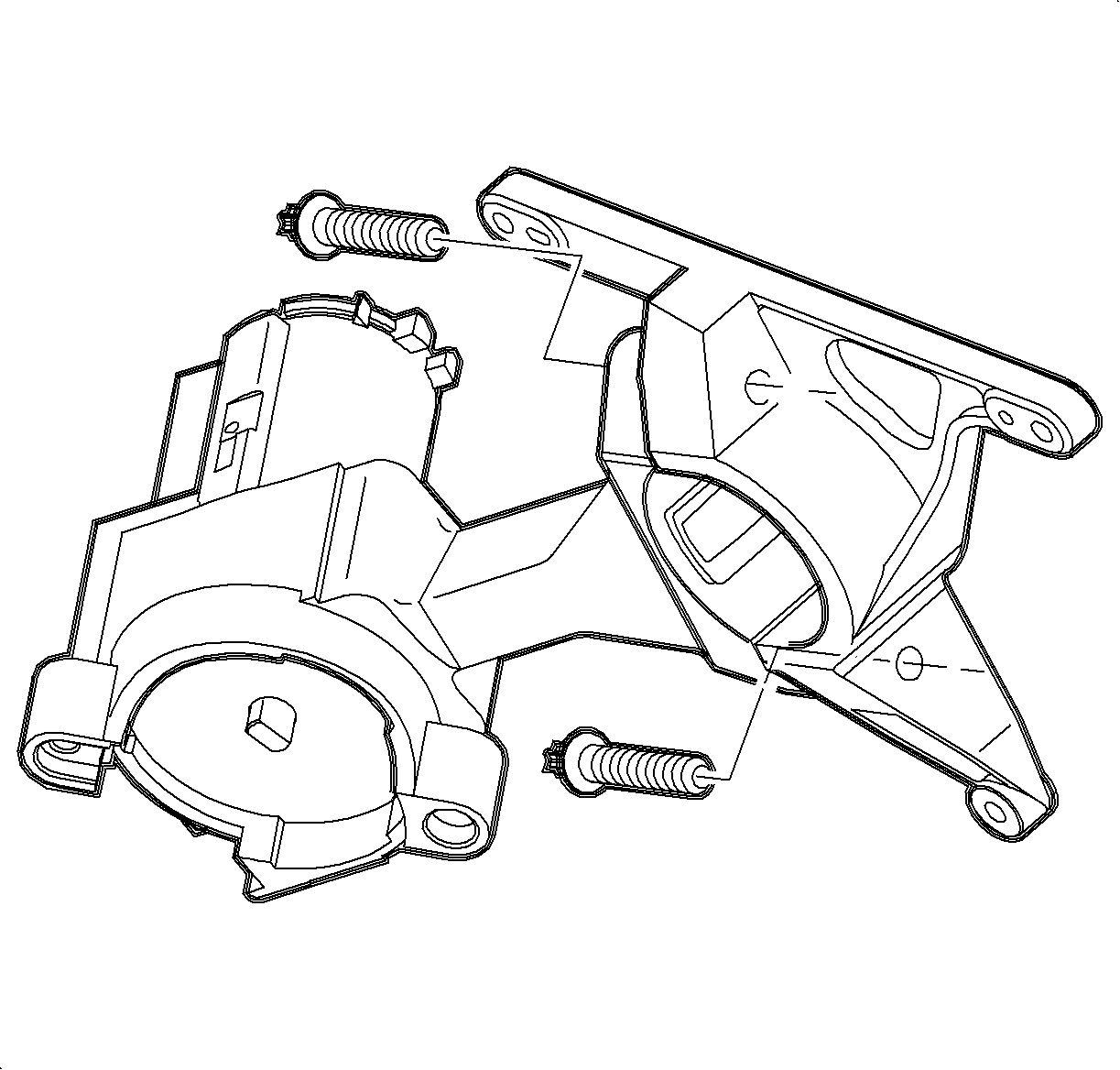
- Remove the ignition module shear bolts.
- Remove the ignition module from the steering column.
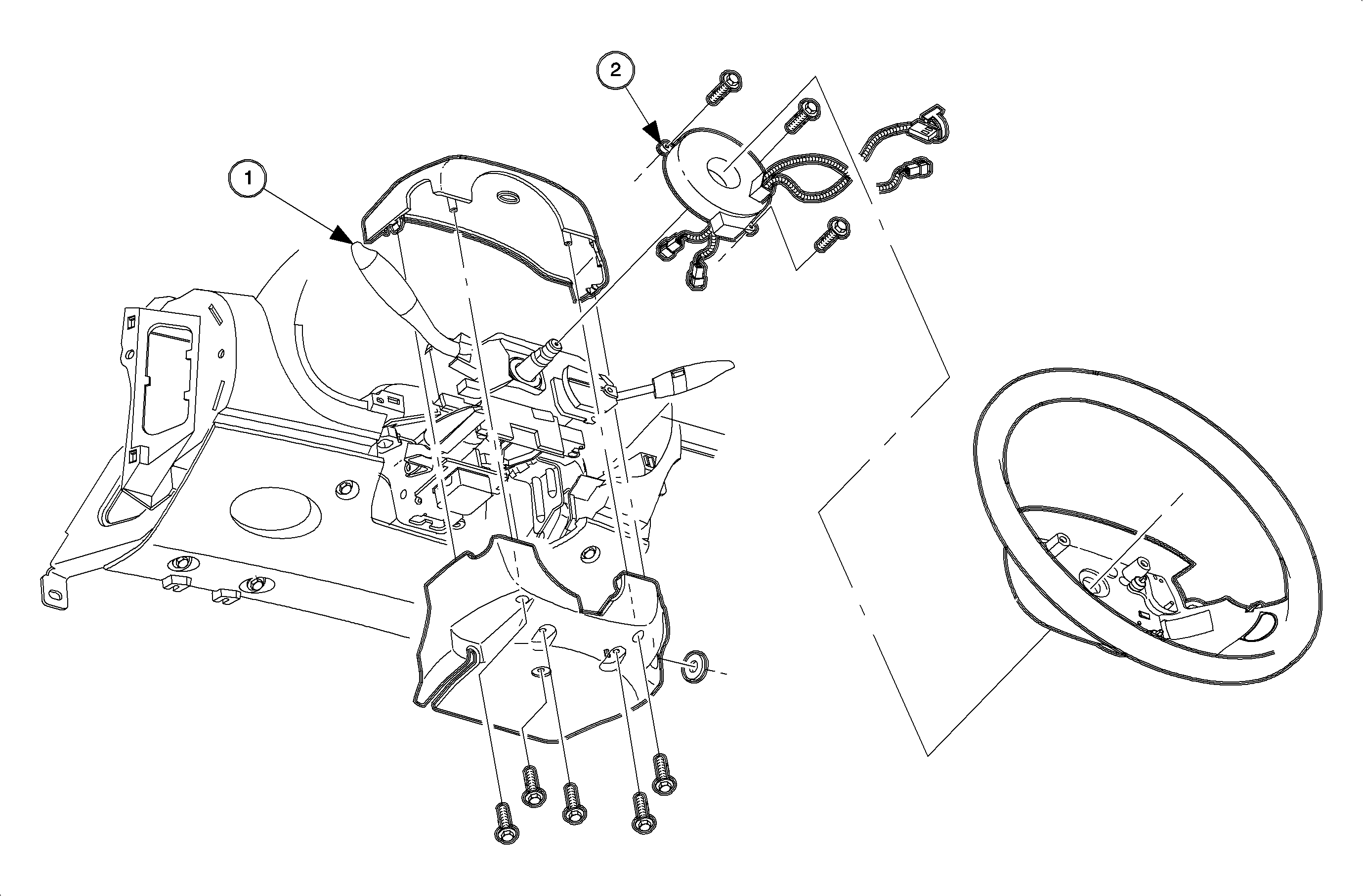
Notice: Cover driver seat to protect seat trim.
Important: If the ignition module assembly/passlock sensor is replaced, the passlock relearn procedure must be performed.
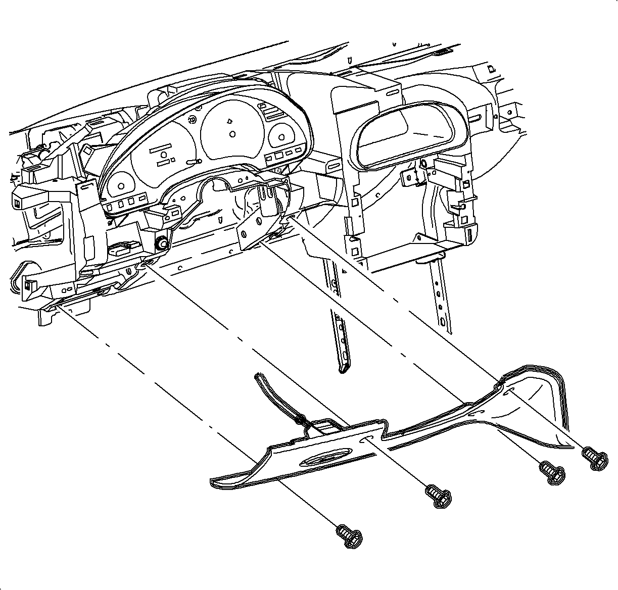
Notice: Protect front of console from being damaged by steering column filler panel.
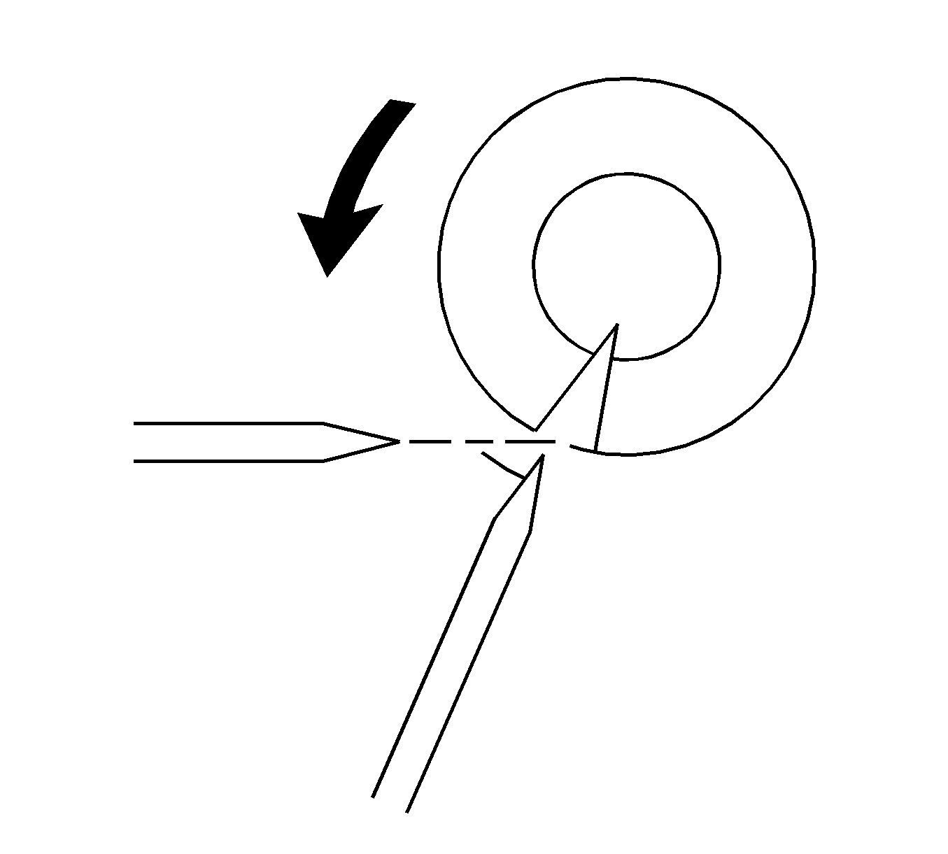
| 10.1. | Use a hammer and chisel to bite into the shear bolt head at a position offset from its center. |
| 10.2. | Tap the chisel to rotate the bolt and loosen it. |
| 10.3. | Repeat until the bolt is loose enough to remove. |
Installation Procedure
- Use new shear bolts to install the ignition module on the steering column. Torque the shear bolts until the heads break off.
- Install harness clamps on the steering column.
- Connect the passlock sensor connector to the ignition module.
- On vehicles with automatic transaxles, connect the park lock cable to the ignition module.
- Reconnect the passlock sensor connector to the ignition module.
- Install the lever control switch by fitting it into bottom locating holes on the ignition module.
- Connect the connectors to the lever control switch. Install the connector position assurance (CPA) retainers.
- Connect the ignition switch electrical connector at the right steering column support bracket bolt.
- Pull the hood release handle forward. Feed the cable under hood release handle and slide the pin in. Connect the cable to the filler panel.
- Install the steering column filler panel and the DLC.
- Install and torque the screws.


Notice: Refer to Fastener Notice in the Preface section.
Tighten
Tighten the steering column filler panel fasteners to 2.2 N·m (19 lb in).
