Service Manual Update for 2000/2001 S Series Automatic Transaxle Service Manuals

| Subject: | Service Manual Update for 2000/2001 S-Series Automatic Transaxle Service Manuals |
| Models: | 2000-2001 Saturn S-Series vehicles equipped with automatic transaxles (RPOs MP6/MP7) |
Purpose
The purpose of this bulletin is to update all 2000/2001 S-Series Automatic Transaxle Service Manuals at your location.
Please obtain all 2000/2001 S-Series Automatic Transaxle Service Manuals and make the necessary updates as indicated below.
| • | Make a photocopy of page 2 in this bulletin as necessary. Cross out page 316 with marker or pen and insert photocopy between pages 316 and 317 of service manual. |
| • | Make a photocopy of pages 3 to 6 in this Bulletins necessary. Insert photocopy of new procedure between pages 324 and 325 of service manual. |
Service Manual update for page 316 of the 2000/2001 S-Series Automatic Transaxle Service Manual. Refer to Technical Information Bulletin 00-T-65. November, 2000.
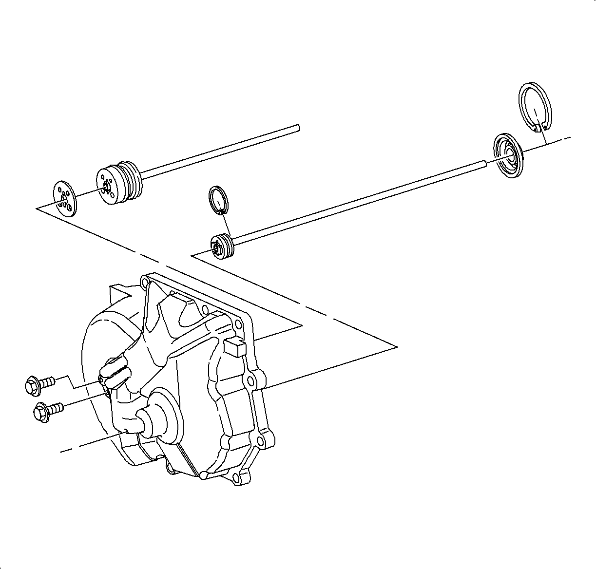
18. Install new input shaft hub-to-end cover gasket in the end cover.
19. Upon installation of input shaft hub, be sure that the roll pin lines up with the slots in the input hub of the end cover.
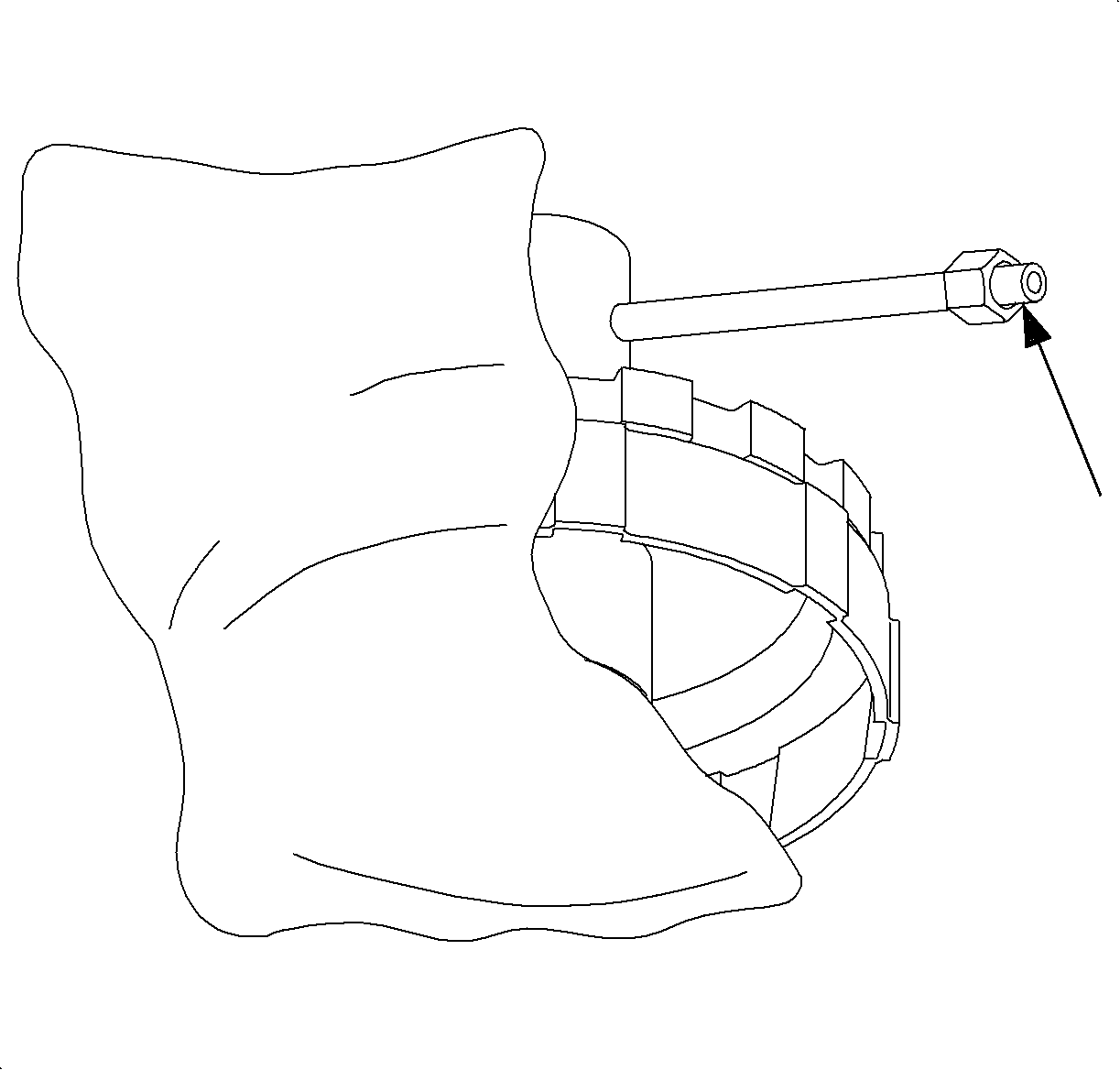
20. On 1st design, install input shaft hub external retaining bolts to end cover.
1st DESIGN SHOWN
Tighten
Input Shaft Pilot Hub-to-End Cover Bolts: 12 N·m (9 lb ft)
Notice: Use new bolts due to insufficient torque retention of the old bolts. When tightening and torquing these bolts it must be done with a hand wrench or torque wrench. Using a power tool will generate excess heat in the faster causing an incorrect torque.
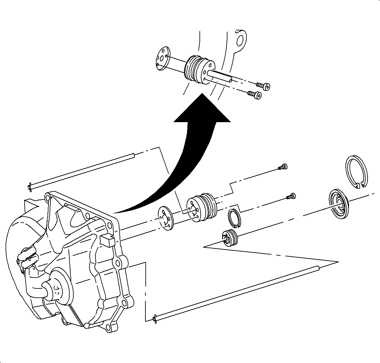
21. On 2nd design, install internal Torx ® bolts inside the input shaft hub.
2nd Design Shown
Tighten
Input Shaft Pilot Hub-to-End Cover Torx® Bolts: 5 N·m (44 in lb)
22. Lube O-ring and install the output shaft hub assembly in the end cover. Make sure seal does not bind up during installation.
23. Install the output shaft hub retaining ring.
24. Install the output shaft lip seal and retaining ring. Make sure lip seal does not bind during installation.
New service procedure for 2000/2001 S-Series automatic Transaxle Service Manual. Refer to Technical information Bulletin 00-T-65. November, 2000.
CLUTCH
TOOLS REQUIRED
| • | SA9146T Clutch Piston Return Spring Compression Fixture |
| • | SA9147T Air Check Fixture |
| • | SA9109T Air Check Fixture |
| • | SA9110T Air Check Fixture |
| • | SA9117T Transaxle Piston Installers |
DISASSEMBLY
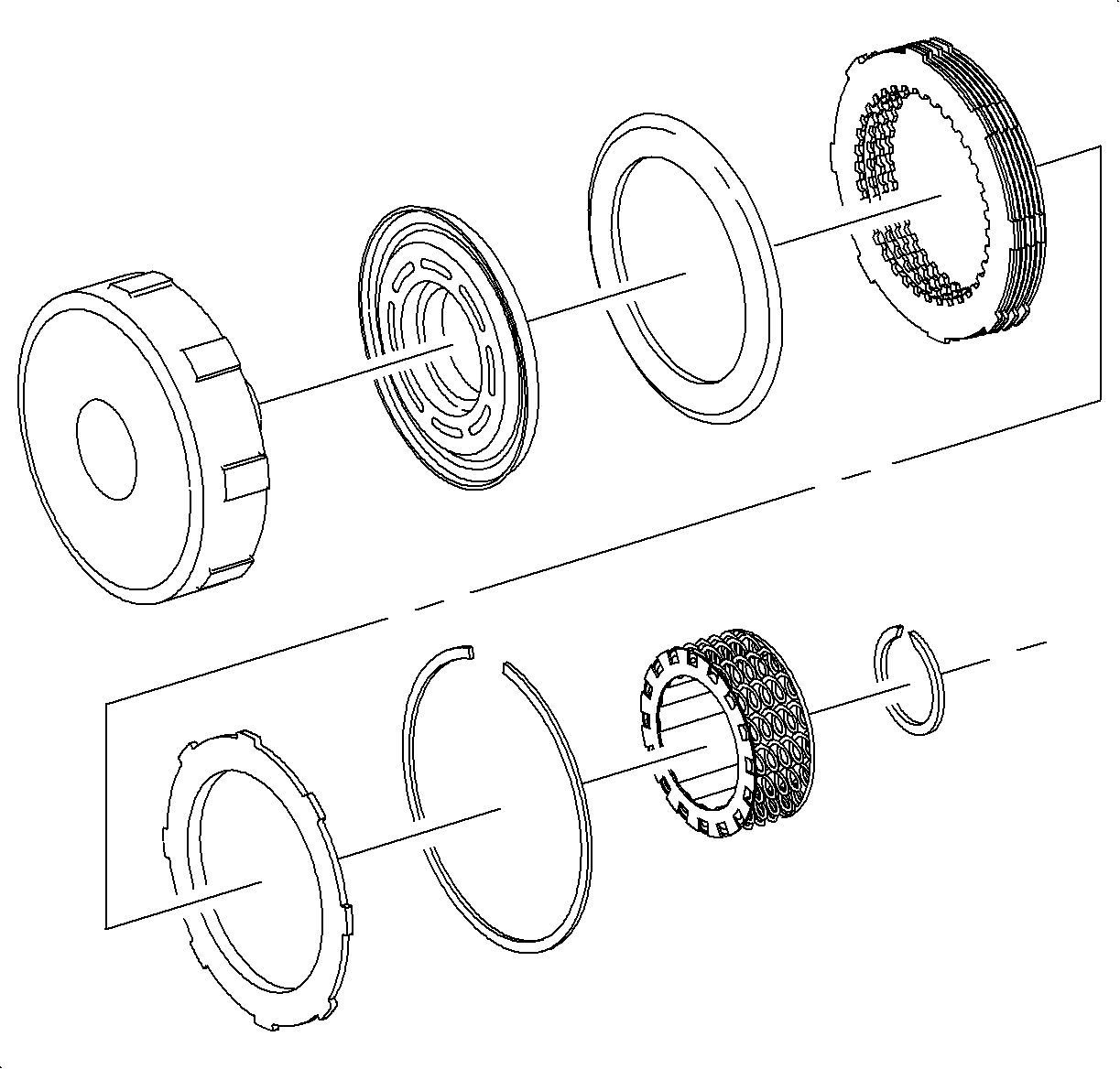
- Disassembly of all clutch assemblies is similar. When disassembling the 1st clutch remove needle bearing by separating bearing from inner race, and the remove 1st gear thrust bearing and washer.
- Remove backing plate snap ring and remove backing plate, clutch plates and 1st clutch apply spring.
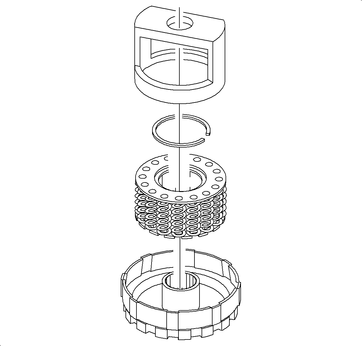
- Install Clutch Spring Compressor SA9146T and compress spring with hydraulic press, or a long bolt, nut and washers.
- Use snap ring pliers to remove spring retaining snap ring.
- Slowly release spring tension and remove return spring assembly.
- Install air check fixture and wrap clutch housing in shop towel. Apply air pressure to housing and blow piston out of its bore.
- 1st clutch only. If the 1st clutch housing is being replaced, new bearing and race will have to be installed.
Important: To prevent possible seal damage, the following steps to remove the clutch apply piston should only be performed if previously diagnosed as being the problem, or if a thorough cleaning is required.
1st -- SA9147T
2nd, 3rd -- SA9109T
4th -- SA9110T
ASSEMBLY
- Clean clutch housing with solvent and air dry.
- Inspect clutch piston lip seals for cracks or damage, replace as necessary.
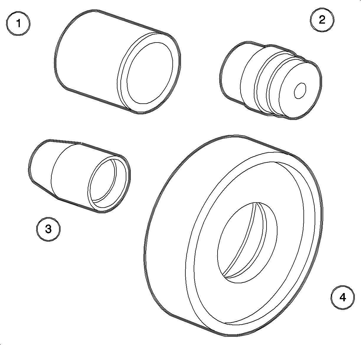
- Clutch pistons are installed using Piston Driver SA9117T - 1 (1) and Piston Replacer SA9117T-4 (4).
- Lube clutch seals with petroleum jelly and place in Piston Replacer SA9117T-4 (4). One side is used for 1st while the other side is for 2nd, 3rd, and 4th.
- Using Piston Driver SA9117T-1, position installer in clutch housing and install piston.
- Inspect piston seals for correct installation.
- Install piston return spring assembly to clutch housing.
- Install Clutch Spring Compressor SA9146T and compress spring.
- Use snap ring pliers to install retaining snap ring.
- On 1st clutch assembly, install 1st clutch apply spring as shown.
- Install apply plate to clutch housing with fiber side up on 2nd, 3rd, and 4th clutch.
- Install 1st clutch plates, starting with an external plate with fiber side up after installing the 1st clutch apply spring.
- Install 2nd, 3rd, and 4th clutch plates starting with a internal tang, alternate plates with fiber side up.
- Install clutch backing plate, and install selective retaining ring.
| • | On 1st clutch, install Seal Protector SA9117T-3 (3) to clutch housing. |
| • | 2nd, 3rd, and 4th clutches require installing Step Plate SA9117T-2 (2) to housing before installing seal protector SA9117T -3 (3). |
| • | ClUTCH -- SPECIAL TOOLS REQUIRED |
| • | 1 -- SA9117T- 1, SA9117T-3, SA9117T-4 |
| • | 2 -- SA9117T -1, SA9117T-2, SA9117T-3, SA9117T-4 |
| • | 3 -- SA9117T-1, SA9117T-2, SA9117T-3, SA9117T-4 |
| • | 4 -- SA9117T-1, SA9117T-2, SA9117T-3, SA9117T-4 |
| Notice: Prior to using clutch piston replacer SA9117T-4, inspect the tool and the clutch housing for any nicks or burns that could damage the clutch piston. |
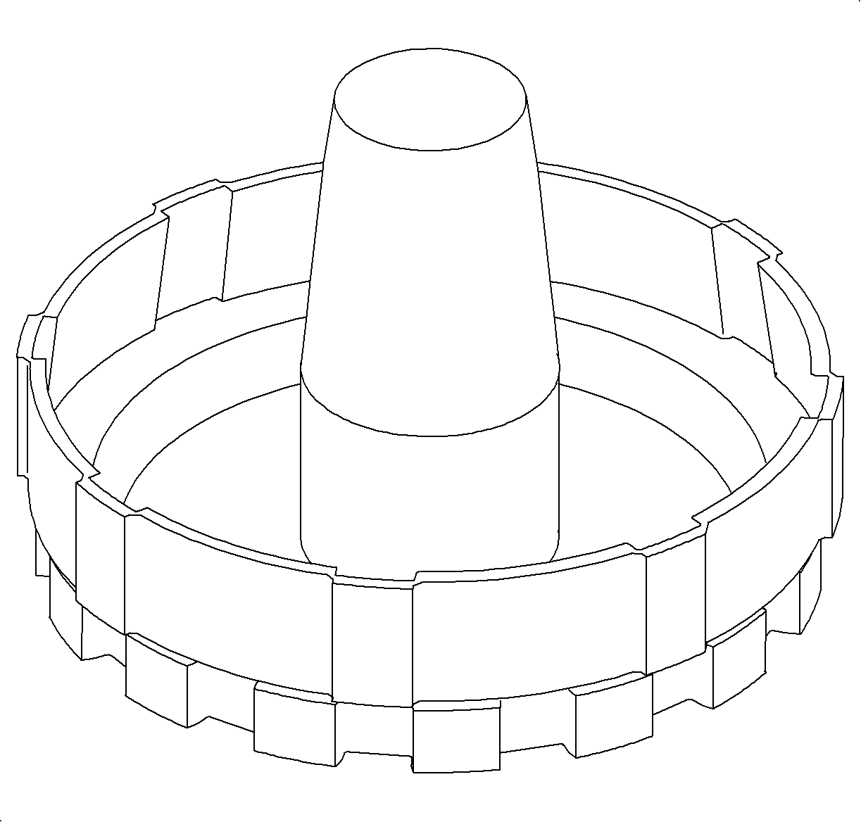
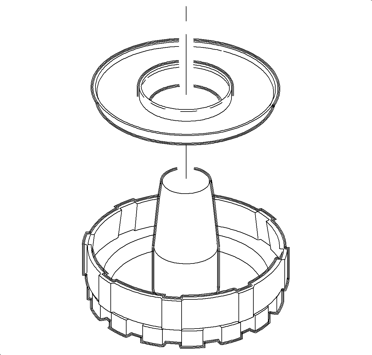

Notice: The piston return spring assembly for 1st clutch is different than the piston return spring assembly for 2nd, 3rd, and 4th clutch.

Important: When installing the 1st clutch apply spring the convex side must be installed towards the clutch piston, and the concave side should be installed towards the clutch pack.
To determine the convex side, lay the 1st clutch apply spring on a flat metal surface. If the surface near the inside diameter is not contact with the flat metal surface, the convex side is pointed upwards. If the surface near the outside diameter is not in contact with the flat surface, the convex side is pointed downwards and is contact with the flat metal surface.Notice: Clutch plates and apply plates must be presoaked for ten minutes in Saturn Transaxle Fluid damage to the friction material may occur.
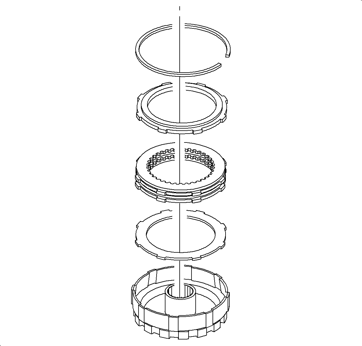
1st clutch: 3 -- internal 3 -- external
2nd clutch: 5 -- internal 4 -- external
3rd clutch: 4 -- internal 3 -- external
4th clutch: 3 -- internal 2 external
