INSPECTION OF FUEL TANK SERIAL NUMBER AND REPLACEMENT

| Subject: | INSPECTION OF FUEL TANK SERIAL NUMBER AND REPLACEMENT, IF NECESSARY |
| Models: | 2000-2001 SATURN S-SERIES VEHICLES (ALL MODELS) |
ALL SATURN RETAILERS and AUTHORIZED SERVICE PROVIDERS
The Highway Safety Act, as amended, provides that each vehicle which is subject to a recall campaign of this type must be adequately repaired within a reasonable time after the owner has tendered it for repair. A failure to repair within sixty (60) days after tender of a vehicle is prima facie evidence of failure to repair within a reasonable time.
If the condition is not adequately repaired within a reasonable time, the owner may be entitled to an identical or reasonably equivalent vehicle at no charge, or to a refund of the purchase price less a reasonable allowance for depreciation.
To avoid having to provide these burdensome remedies, every effort must be made to promptly schedule an appointment with each owner and to repair their vehicle as soon as possible. As you will see in reading the attached copy of the owner letter, the owners are being instructed to contact the Saturn Customer Assistance Center if their Retailer does not remedy the condition within five (5) days of the mutually agreed upon service date. If the condition is not remedied within a reasonable time, owners are instructed on how to contact the National Highway Traffic Safety Administration.
Defect Involved
Saturn has decided that certain 2000 and 2001 S-Series Saturn vehicles fail to conform to Federal Motor Vehicle Safety Standard (FMVSS) 301, "Fuel System Integrity." Some of these vehicles have been produced with an inadequate vent valve weld on the top portion of the fuel tank. Fuel spillage could occur during refueling or if a vehicle were involved in a rollover. If an ignition source were present, a fire could result.
To prevent the possibility of this condition occurring, Saturn Retailers will inspect, and, if necessary, replace the fuel tank assembly.
Vehicles Involved
Only selected 2000-2001 model year Saturn S-Series vehicles within the following VIN ranges will require this campaign.
2000 Model Year VIN Range (All Models) = YZ262962-YZ267976
2001 Model Year VIN Range (Coupe Only) = 1Z116256-1Z117687
2001 Model Year VIN Range (All Models) = 1Z200071-1Z200150
You must verify campaign involvement through your AS400 system. It is important to note that campaign claims will only be paid on involved vehicles.
Owner Notification
Owners of all involved vehicles will be notified of this campaign by Saturn. Refer to the owner letter included in this bulletin.
Facility VIN Listing
A list of vehicles assigned to you (Facility VIN Listing), which our records indicate were sold by or shipped to you, (or are located in close proximity to your facility) is enclosed.
This listing contains:
| • | Owner’s name with address and telephone number; |
| • | Complete vehicle identification number (VIN); and |
| • | VINs of vehicles, which according to Saturn records are in retail stock. |
The Facility VIN Listing (with owner information) is furnished to involved Retailers with the Product Campaign Bulletin. Although these vehicles are assigned to your facility, it is important to note that owners may elect to have their vehicle serviced at the Saturn Retail Facility of their choice. Those Retailers not involved initially in this campaign will receive a message at the top of a blank Facility VIN Listing that states: NO VEHICLES ASSIGNED AT THIS TIME FOR CAMPAIGN 01-C-02.
Retailer Responsibility
All unsold vehicles in Retailers’ possession and subject to this campaign must be held at the retail facility and repaired per the service procedure included in this campaign bulletin before owners take possession of these vehicles.
Retailers are to service all vehicles subject to this campaign at no charge to owners, regardless of mileage, age of vehicle, or ownership, from this time forward.
Owners of vehicles recently sold from your vehicle inventory are to be contacted by the Retailer and arrangements made to make the required correction according to the procedure contained in this bulletin.
In summary, whenever a vehicle subject to this campaign enters your vehicle inventory, or is in your retail facility for service in the future, please take the steps necessary to be sure the campaign correction has been made before selling or releasing the vehicle.
This bulletin is notice to you that the new motor vehicles included in this campaign may not comply with the standard previously identified. Under 49 U.S.C. section 30112 of the Highway Safety Act as amended, it is illegal for a retailer to sell a new motor vehicle which the retailer knows does not comply with an applicable Federal Motor Vehicle Standard. As a consequence, if you sell any of these motor vehicles without first performing the campaign correction, your retail facility may be subject to a civil penalty up to $1,100 for each such a sale.
Transfer of Campaign Responsibility
Saturn vehicles that have been sold by you, which may be closer in proximity to another Saturn Retailer, may still appear on your Facility VIN Listing. If either you or the vehicle owner determines that it is more desirable for a vehicle on your Facility VIN Listing to be serviced by another Saturn Retailer, or if the customer’s address has recently changed, campaign responsibility may be transferred by completing the following:
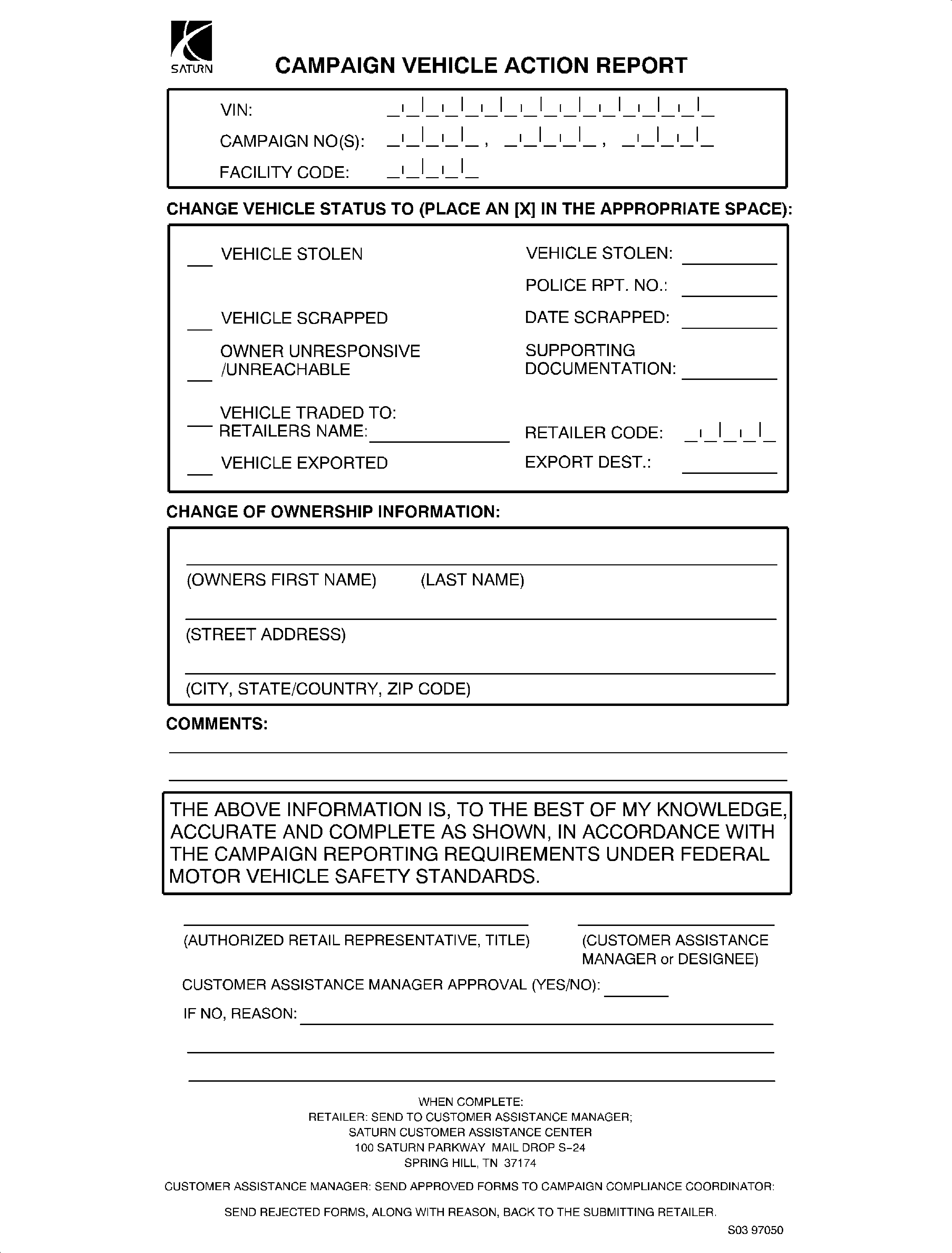
| • | Submit a Campaign Vehicle Action Report to your Customer Assistance Manager (CAM) at the Saturn Customer Assistance Center; OR |
| • | Submit an update in owner information to the Saturn Owner of Record system, via SERVICELINE XL, for Saturn Customer Assistance Center review and approval. |
A copy of the Campaign Vehicle Action Report is included for your reference. Additional copies can be ordered from Saturn Publications (1-800-828-2112, prompt 3, Item# S0397050). All changes to campaign responsibility will be reflected in your next Unfixed VIN Report.
All other changes in vehicle status (e.g., scrapped, stolen, etc.) are to be made in accordance with section 4.4.3 of the Retailer Service Reference Guide, Notifying Saturn of Vehicle Status Change.
Parts Information
- A pre-shipment of fuel tank assemblies and components required to perform this campaign has been automatically sent to each Retailer from Saturn Service Parts Operations (SSPO). These initial parts shipments are to aid the Retailers in campaign preparation and will ensure minimal customer inconvenience. Further shipments will automatically be sent at a later date to fulfill your forecasted parts requirements.
- Should additional parts be required, please order as needed.
- Required Parts:
Part Number | Description | Quantity Required to Replace Tank | Quantity Required to Remove Tank and Inspect FLVV |
|---|---|---|---|
21007370 | Tank Asm - Fuel | 1 | 0 |
21008100 | Seal - Fuel Sdr (O-Ring) | 1 | 0 |
21020792 | Strap - Tie (8 per package) | 1 | 0 |
21007292 | Retainers - Fuel Feed Pipe Conn (3/8 in) | 2 | 2 |
17122771 | Retainers - F/Injr (5/16 in) | 3 | 2 |
Disposition of Replaced Parts
Retailers will scrap all replaced parts in a manner that ensures that they cannot be reused, remanufactured, or otherwise entered into the stream of commerce in the future.
Suggestions for Ensuring Customer Satisfaction
As you know, Saturn’s success hinges upon our ability to execute superior customer support throughout the ownership experience, especially when important corrective actions such as this are required.
It is imperative that every effort is made to accommodate the affected owners. Additionally, priority should be given to customer vehicles over retail inventory vehicles. If you have any questions, please coordinate with the Saturn Customer Assistance Center to help ensure customer satisfaction.
Service Procedure
Fuel Tank Inspection
- Raise the vehicle on the hoist.
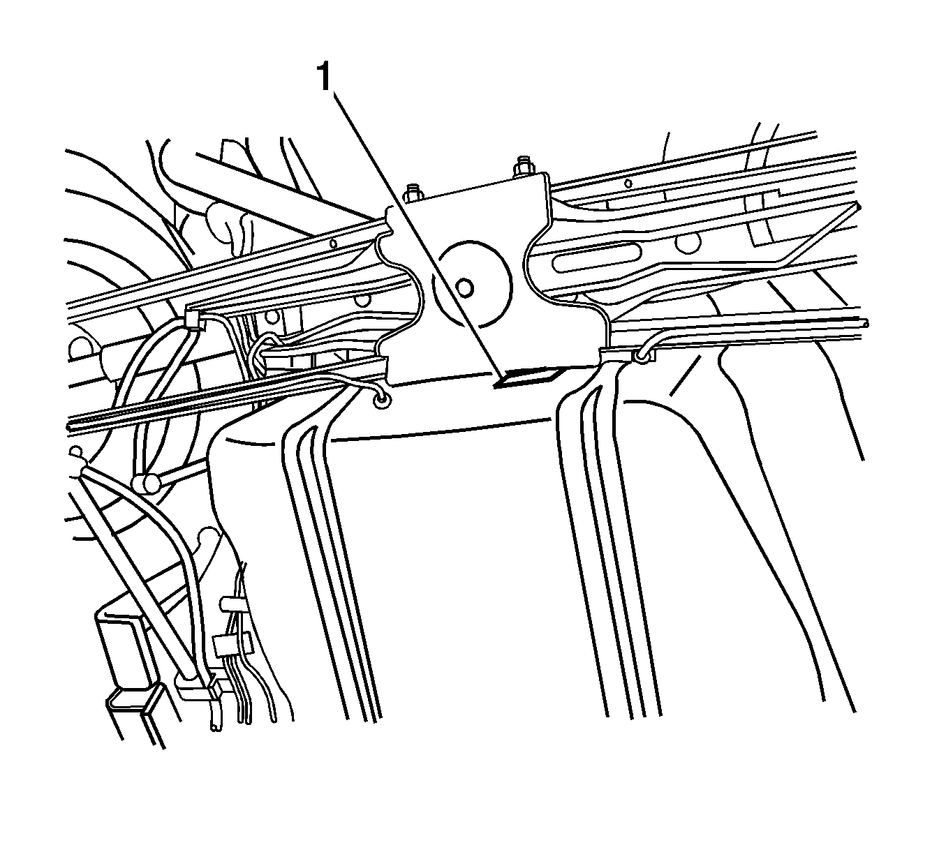
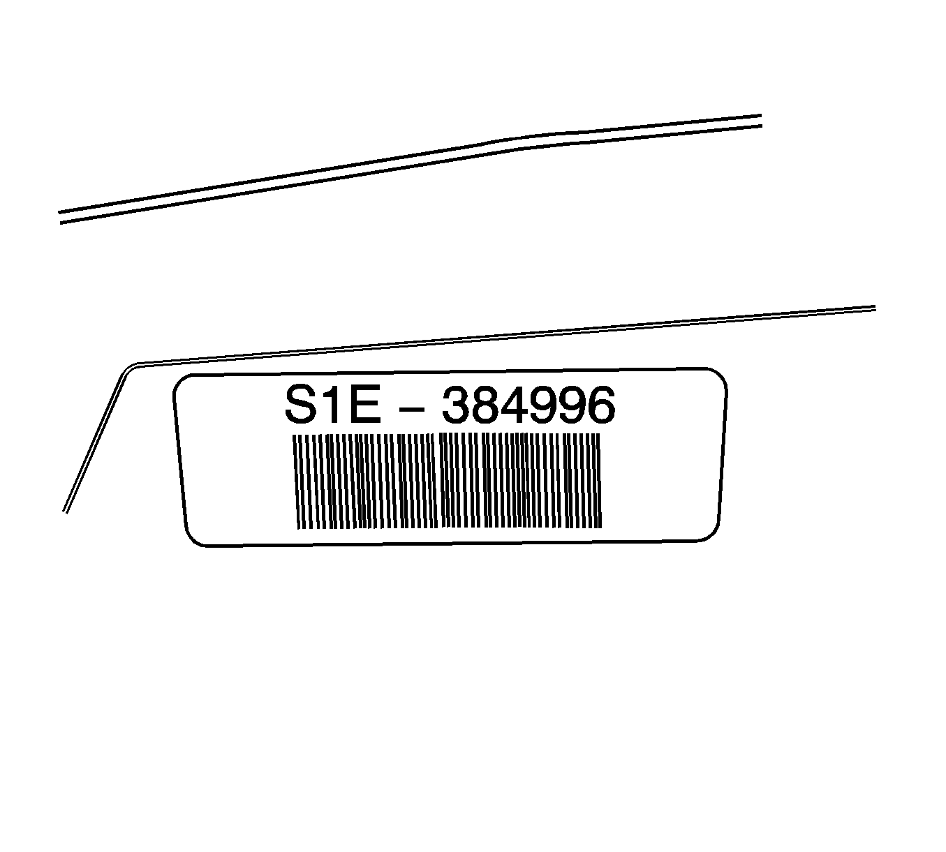
- Locate the fuel tank bar-code label on the rear of the tank assembly near the fuel filler inlet (refer to illustration). If the fuel tank mounting strap partially covers the fuel tank bar-code label, it will be necessary to support the fuel tank and the lower fuel tank mounting strap to read the serial number. If no fuel tank bar-code label is present, continue to Fuel Tank Inspection/Replacement on page 8 of this bulletin.
- Write down the serial number from the fuel tank bar-code label on the customer service order.
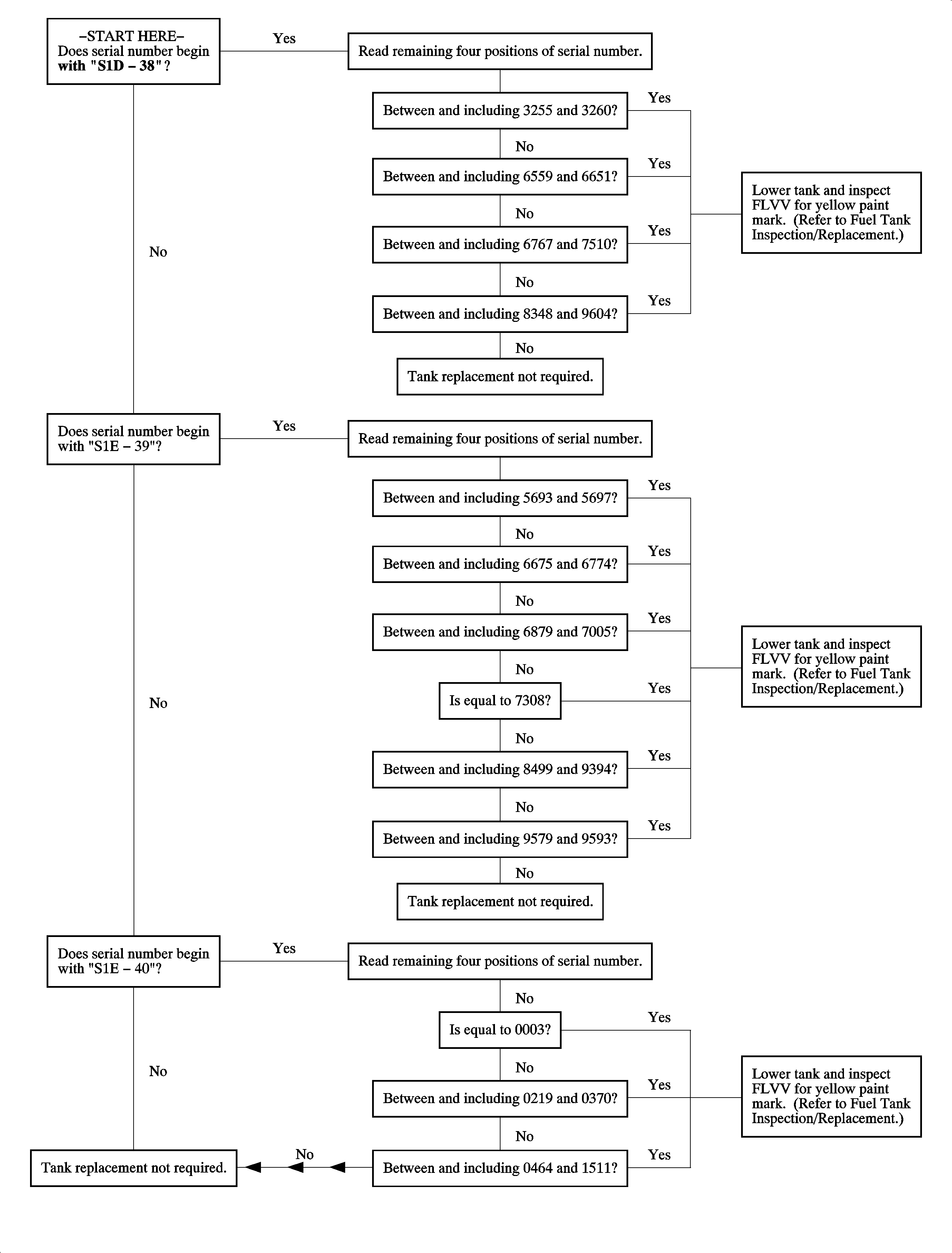
- Using the serial number recorded from the fuel tank bar-code label, perform the Fuel Tank Serial Number Inspection located on the facing page to determine whether the fuel tank is affected by this campaign.
- If the fuel tank mounting strap had to be lowered to read the fuel tank bar-code label, install the fuel tank mounting strap.
- Lower the vehicle and affix the Campaign Completion Label on a clean, dry surface of the radiator core support, in an area clearly visible when the hood is raised. For more information, refer to the Campaign Completion Label in this bulletin.
Caution: Ensure vehicle is properly supported and squarely positioned on hoist. To avoid personal injury when vehicle is on hoist, provide additional support for vehicle on opposite end from which components are being removed.
| • | If the flow chart leads to "Lower tank and inspect fill limit vent valve (FLVV) for yellow paint mark," continue to Fuel Tank Inspection/Replacement on page 8 of this bulletin. |
| • | If flow chart leads to "Tank replacement not required," continue to the next step. |
Tighten
Tighten the fuel tank straps-to-body to 47 N·m
(35 lb ft).
Fuel Tank Inspection/Replacement
Caution: Do not allow smoking or the use of open flames in the area where work on the fuel system is taking place.
Caution: Fuel supply lines will remain pressurized for long periods of time after the engine is shut off. This fuel system pressure must be relieved before servicing the fuel system.
Caution: Whenever fuel line fittings are loosened or removed, wrap a shop rag around the fitting and have an approved container available to collect any fuel.
Caution: Never drain or store fuel in an open container due to the possibility of fire or explosion.
Drain Fuel Tank
- Connect the scan tool to vehicle data link connector (DLC) and start the vehicle.
- Relieve fuel system pressure by commanding the fuel pump Off with the scan tool.
- Leave the ignition On and raise the vehicle to a comfortable working height. Keep the scan tool outside of the vehicle and accessible from under the car.
- Disconnect the fuel feed line (5/16 in) at the inlet to fuel filter.
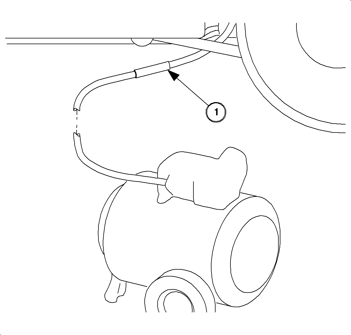
- Connect the 5/16 X 1/4 in quick connect (1) adapter from Fuel/Pressure Adapter SA9127E-7 into the fuel feed line.
- Connect a suitable fuel hose to the adapter fitting and connect the other end of the hose to the certified fuel handling cart.
- Use the scan tool to energize the fuel pump and completely drain the fuel tank. Once the fuel pump is commanded On using the scan tool, it will run for 1 minute before timing out and shutting Off. Continue to cycle the fuel pump On until the fuel tank is completely drained.
Remove Fuel Tank Assembly
- Disconnect the negative battery cable.
- Remove the fuel filler cap.
- Remove the driver side rear wheelhouse liner.
- Remove the upper fuel filler pipe attachment screw. The screw is located under the quarter panel grommet at the 1:00 position of the fuel filler pipe. Gently pull the quarter panel grommet outward to gain access to the screw.
- Disconnect the wiring harness connector from the evaporative emission (EVAP) canister vent solenoid.
- Remove the fuel filler pipe lower bracket attachment screw (10 mm hex) at the underbody left hand side rail.
- Remove the quarter panel grommet from the fuel filler pipe.
- Raise the vehicle and disconnect the EVAP canister vent pipe at 5/8 in quick connect to the canister vent hose.
- Loosen the fuel filler pipe hose clamp (7 mm hex) closest to the fuel tank.
- Disengage the fuel filler pipe hose from the fuel tank and remove the fuel filler pipe from the vehicle. Keep the fuel filler pipe as level as possible when removing from the tank. The fuel fill check valve may contact the inlet neck of the tank, so use care when removing. If the fuel fill check valve is dislodged from the fuel filler pipe, it may remain in the tank.
- Remove two screws (10 mm hex) that attach the fuel filter/pressure regulator bracket to the vehicle.
- Disconnect the fuel feed line (90° quick-connect) from the outlet of the filter/pressure regulator.
- Disconnect the fuel vapor/canister purge line at 90° quick-connect adjacent to the fuel filter/pressure regulator.
- Slide the fuel filter/pressure regulator bracket out from under the brake lines.
- With the aid of an assistant, remove the two tank retaining strap bolts (15 mm hex) and lower the tank enough to disconnect the two electrical connectors to the fuel pump and tank pressure sensor.
- Remove the fuel tank from the vehicle.
- Inspect the fill limit vent valve (FLVV) (1) on the top rear surface of the fuel tank for a yellow paint marking. The yellow paint marking can be any kind of yellow marking (i.e., yellow dot, yellow line, yellow check mark, etc.).
- Obtain the replacement parts. Refer to Parts Information in this bulletin.
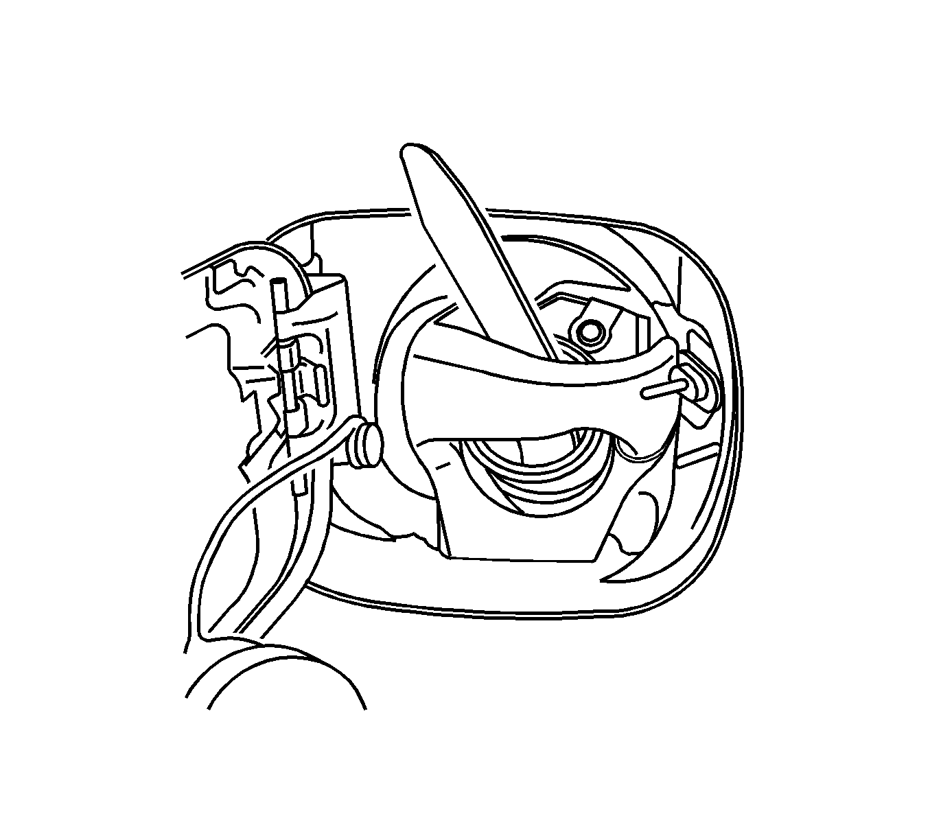
| 7.1. | Move the fuel filler pipe as far rearward as possible in the fuel door opening. |
| 7.2. | Go through the wheelhouse opening with one hand while guiding the quarter panel grommet through the fuel door opening, and over the fuel filler pipe. |
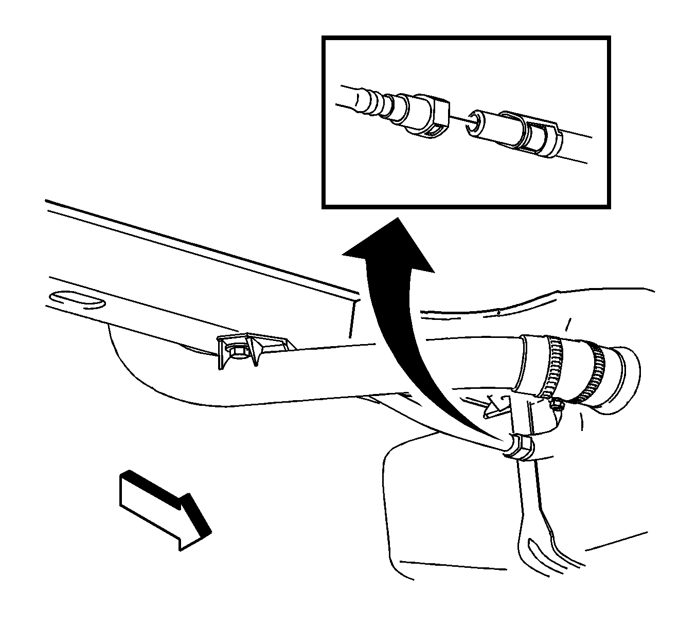
Caution: Several ounces of fuel may remain in the fuel filler pipe due to the design of the inlet check valve. Be aware of this when handling the fuel filler pipe during removal from the fuel tank. Wrap the inlet check valve with a shop rag and hold it in place by hand. Unseat the check valve and drain any fuel into an approved container.
Important: To provide space to remove the fuel filler pipe, guide the top of the fuel filler pipe into the quarter panel opening while removing the fuel filler pipe.

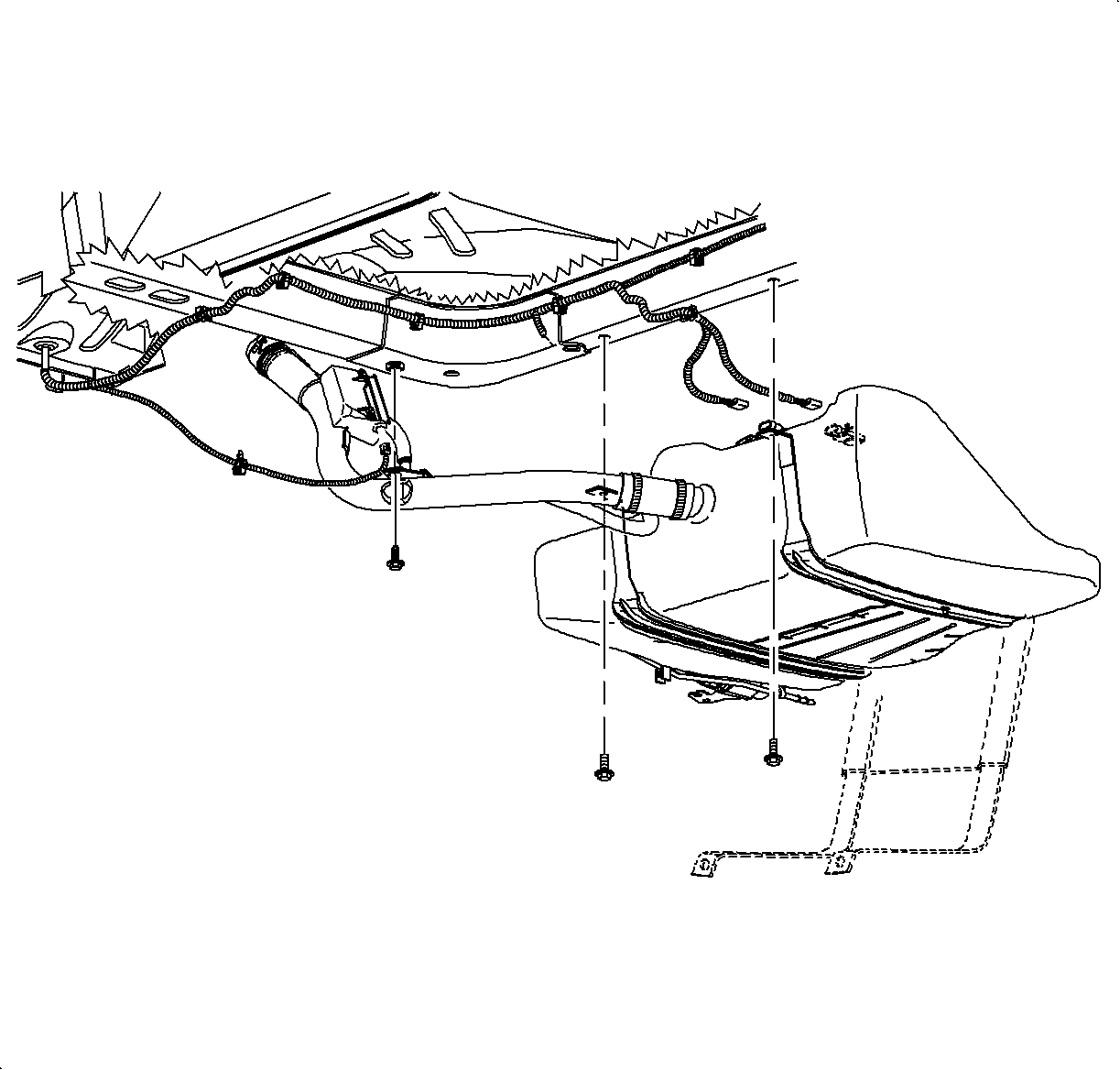
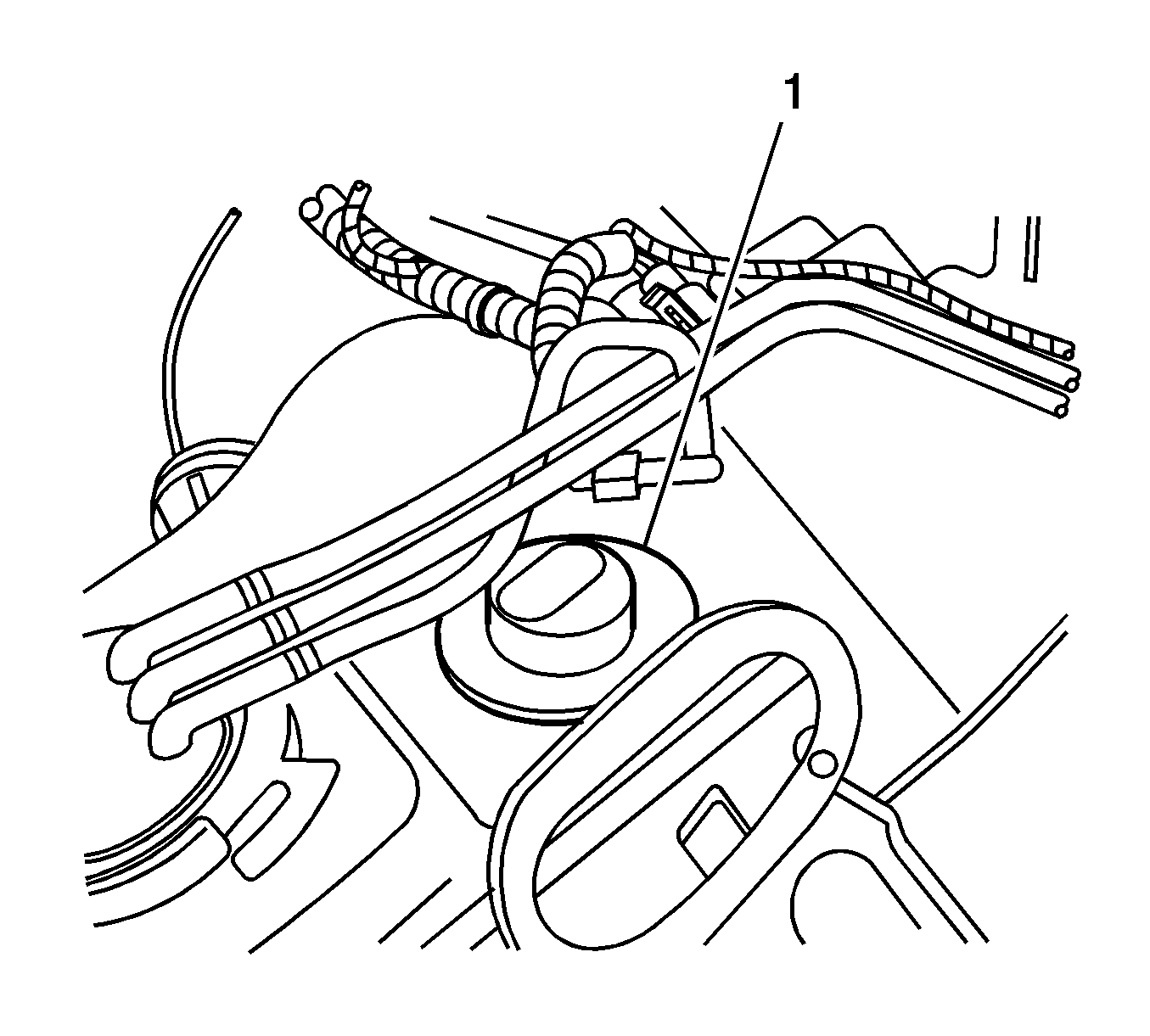
| • | If the yellow paint mark is present on the FLVV, the fuel tank must be replaced. Continue to the next step. |
| • | If the yellow paint mark is not present on the FLVV, reinstall the fuel tank. Continue to Install Fuel Tank Assembly on page 16 of this bulletin. |
Transfer Fuel Tank Pressure Sensor to Replacement Fuel Tank Assembly
- Use fingertips and light pressure to disengage furl tank pressure sensor from locating tangs at end of connector housing (2).
- Use a flat bladed screwdriver to remove fuel tank pressure sensor from fuel tank mounting pad (3).
- Install fuel tank pressure sensor on mounting pad of replacement fuel tank assembly.
- Ensure proper alignment of locating tangs at connector end of fuel tank pressure sensor.
- Install a new tie strap and latch fuel tank pressure sensor retaining arm.
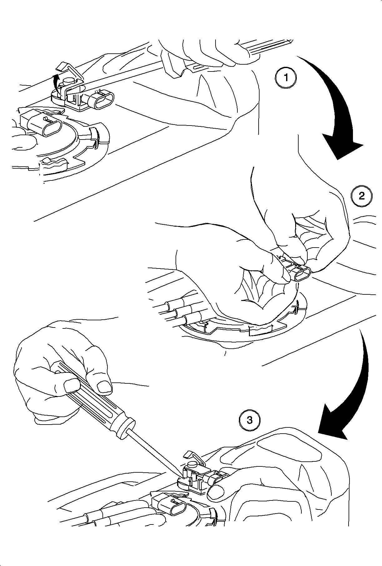
Notice: Use care when removing fuel tank pressure sensor. Avoid contact of any tool with top surface of fuel tank pressure sensor. If this surface is damaged, fuel pressure sensor will have to be replaced.
Cut tie strap and use a flat blade screwdriver to unlatch fuel tank pressure sensor retaining arm (1).
Transfer Fuel Tank Pump Module to Replacement Fuel Tank Assembly
- Disconnect the fuel feed and return lines from the filter/regulator assembly (1).
- Disconnect fuel pump vapor line from fuel tank vent pipe (2).
- Use Fuel Tank Lock Ring Remover SA9156E and remove the fuel pump module retaining ring. A ½ in drive ratchet/breaker bar (approximately 18 in long) will easily loosen and remove the lock ring (3).
- To prevent bending of the sending unit float arm during removal, lift the pump module up slightly to disengage orientation tabs and rotate the module 90° clockwise until the fuel lines are facing the 1:00 position (12:00 is toward the front of the tank).
- Carefully lift the fuel pump module (with sending unit) straight up from the fuel tank until the bottom of the pump module is very close to the fuel tank opening. Then, tilt the pump module about 45° toward the right side of the tank and simultaneously lift it up and out of the tank opening, watching that the level sender float arm is not being bent.
- Discard the fuel pump module to tank seal.
- Verify that the float arm on the fuel level sender has not been bent by standing the fuel pump module on a flat, horizontal surface and measuring the distance from this surface and the bottom of the float. A 5/32 in diameter drill bit can be used as a gage. The gage must freely pass between the float and the horizontal surface with no more than 1/16 in clearance.
- Inspect the replacement fuel tank and clean the fuel tank seal groove of any foreign debris before installing a new seal.
- Carefully install the fuel pump module with the sending unit in the fuel tank by orienting the float to face the right side of the tank, tilting the pump module approximately 45°, and loading the float arm and pump into the tank opening. Insert the pump module all the way down into the tank and then rotate 90° counterclockwise to align the module orientation tabs with slots in the tank opening. Correctly oriented, the lines from the pump module will be facing the 10:00 position (12:00 is front of tank).
- Install the retaining lock ring using the service tool SA9156E.
- Connect the fuel pump vapor line to the fuel tank vent pipe.
- Connect the fuel feed and return lines to the filter/pressure regulator and pull back to confirm positive engagement.
- Position the fuel feed, fuel return, and EVAP canister purge line in the fuel tank retaining clip and "snap" shut.
- Install the "loose" retainer clip around the fuel feed, return, and purge line at upsets and "snap" closed.
Notice: Clean all the fuel pipes, hose connections, and surrounding areas prior to disassembly to prevent fuel system contamination.
Notice: To prevent retainer damage, do not attempt to remove retainer with a 12 in or shorter ratchet/breaker bar.
Important: Spray the fuel pump module cam-locking tang with penetrating oil prior to attempting removal.
Notice: Care must be taken not to bend or twist the fuel pump filter or sending unit float arm during removal/installation of the fuel pump module. A damaged fuel pump filter restricts fuel flow to the pump, and a bent sending unit float arm will not provide accurate readings. Care must also be taken to ensure the fuel pump module is not dropped. Dropping a fuel pump module can dislodge internal components and cause excessive noise and/or internal leakage.
Important: Always replace the fuel pump module to tank seal (O-ring) whenever the assembly is removed. The correct seal is green in color. Do not use the older black seal.
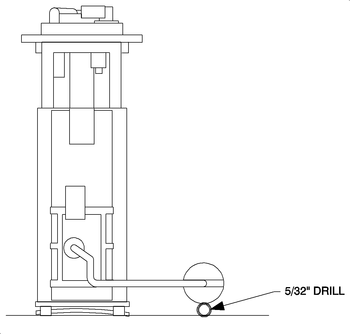
Notice: If the float arm requires repositioning to meet appropriate clearance specification, ensure that any bending is performed at the 90° bend near the level sender. The short section of the float arm going into the level sender must be supported so that bending does not take place at the level sender.
Important: The fuel pump retaining ring cannot be properly installed if the pump flange locator tabs are not aligned with the slots in the tank.
Notice: Replace the plastic fuel line retainers whenever the fuel supply lines are disconnected at the fuel filter/pressure regulator and fuel rail. Install the new retainer into the female portion of the connection. Care must be taken to assure that the locking tab is centered in the window of the female connection. Firmly press the male and female portions together until a "click" is heard, then pull firmly back to confirm engagement.
Transfer EVAP Canister to Replacement Fuel Tank Assembly
- Disconnect the 5/8 in 90° fuel tank vapor inlet hose fitting from the EVAP canister.
- Remove the EVAP canister retainer clip at the top of the canister.
- Install the EVAP canister in the mounting pocket on top of the replacement fuel tank assembly.
- Install the EVAP canister retainer clip at the top of the canister. Ensure the retainer clip is installed over the lower flange of the canister before snapping into place.
- Install the 5/8 in 90° fuel tank vapor inlet hose fitting to the TANK port on the EVAP canister.
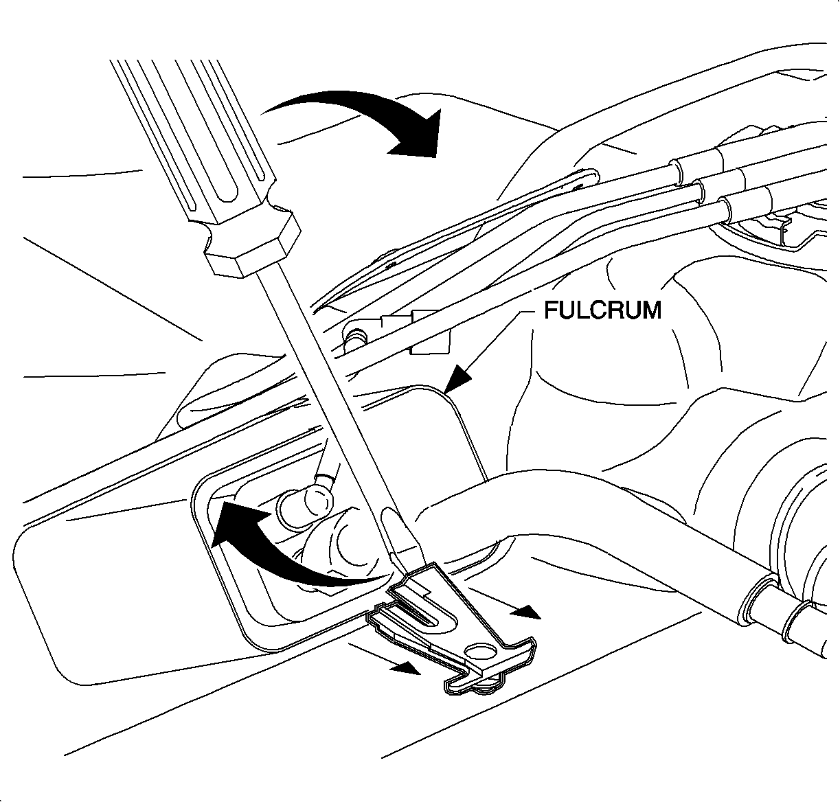
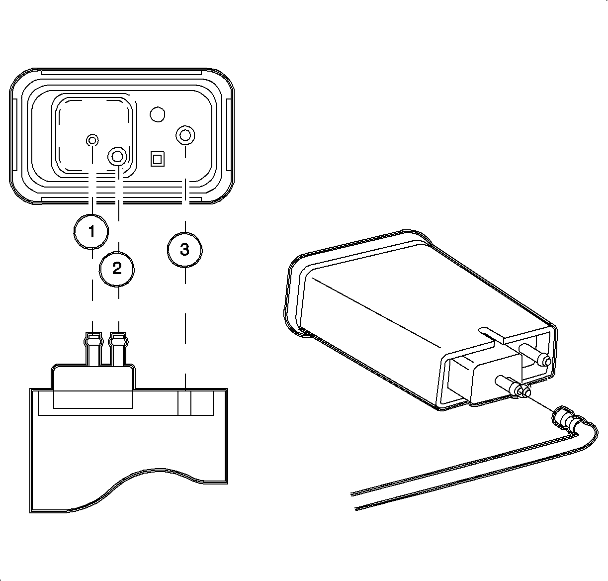
Notice: Install the purge fitting quick connector retainer into the female portion of the
connector. Care must be taken to ensure the locking tab is centered in the window
of the female connector.
• Canister Purge (1) • Vapor (2) • Vent (3)
Install Fuel Tank Assembly
- With the aid of an assistant, position the fuel tank under the vehicle.
- Attach the electrical connectors to the fuel pump and tank pressure sensor.
- Reposition the fuel tank mounting straps and shield around the tank, and install the strap mounting bolts (15 mm hex) to underbody.
- Install two mounting screws (10 mm hex) for the fuel filter/pressure regulator bracket.
- Install a new retainer into the female portion of the 90° quick-connect fitting on the underbody fuel feed line.
- Install the underbody fuel feed line onto the outlet of the filter/regulator.
- Ensure the fuel filler check valve is in place at the end of the fuel filler pipe.
- Position the filler pipe into the wheel opening with the top of the pipe within the body panel opening.
- Install the fuel filler pipe into the fuel tank opening.
- Lower the vehicle and move the fuel filler pipe to the rear of the fuel door opening. Starting with the front portion, install the quarter panel grommet around the fuel filler neck and work down through the fuel door opening.
- At location of upper fuel filler pipe attachment screw, pull just enough of quarter panel grommet out through fuel door opening and up over top of fuel filler pipe. Insert a flat blade tool inside fuel filler pipe between quarter panel grommet and fuel filler pipe edge to hold quarter panel grommet in place while installing upper attachment screw.
- Raise the vehicle and install the fuel filler pipe lower bracket attachment bolt.
- Lower the vehicle and install the fuel filler pipe upper bracket attachment screw.
- Carefully remove the flat-blade tool that was previously installed and route the quarter panel grommet over the top of the fuel filler pipe.
- Use a blunt end tool, such as a plastic tool, to carefully push the remaining portion of the quarter panel grommet under the edge of the fuel door opening as needed. Use care not to cut or damage the quarter panel grommet.
- Raise the vehicle to a comfortable working height.
- Tighten the hose clamp (7 mm hex) on the fuel filler pipe hose at the fuel tank inlet neck.
- Connect the wiring harness connector to the EVAP canister vent solenoid.
- Install the driver side rear wheelhouse liner to the rear wheel opening.
- Add the fuel to fuel tank and install the fuel filter cap.
- Connect the negative battery cable.
- Prime fuel system using either of the following methods:
- Examine all the fuel line fittings that were disconnected for signs of leakage.
- Start the engine. Only crank the engine for a maximum of 15 seconds.
- Using the scan tool, perform the EVAP Service Bay Test. This test will verify the integrity of the vapor handling areas of the fuel system. Refer to SSS/Tech 2 User Guide for information on performing this test.
- Affix the Campaign Completion Label on a clean and dry surface of the radiator core support, in an area clearly visible when the hood is raised. For more information, refer to Campaign Completion Label in this bulletin.
Notice: Position the fuel tank solidly against the left hand underbody side rail prior to tightening the strap mounting bolts. A small white locator button on the left side of the fuel tank shell should be tight against the left side rail at the completion of installation.
Tighten
Tighten the fuel tank straps-to-body to 47 N·m
(35 lb ft).

Tighten
Tighten the fuel filter/pressure regulator-to-frame
rail to 8 N·m (71 lb in).
Notice: Replace the plastic fuel line retainers whenever the fuel feed lines are disconnected at the fuel filter/pressure regulator and fuel rail. Install the new retainer into the female portion of the connection. Care must be taken to assure that the locking tab is centered in the window of the female connection. Firmly press the male and female portions together until a "click" is heard, then pull firmly back to confirm engagement.
Important: Lubricate the male ends of the fuel filter/pressure regulator with clean engine oil to ease installation.
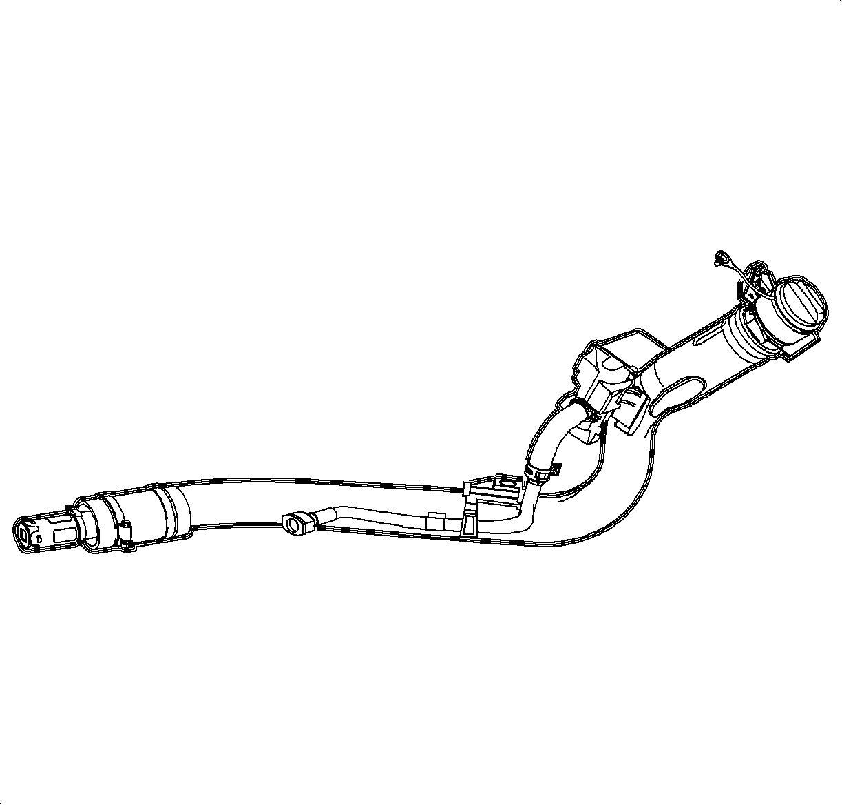
Important: To ease installation, lightly wipe the outside of the fuel tank inlet connector with plain water.

Tighten
Tighten the fuel filler pipe lower attachment bolt
to 8 N·m (71 lb in).
Tighten
Tighten the fuel filler pipe upper attachment screw
to 4 N·m (35 lb in).
Important: Ensure the fuel filler pipe connecting hose is installed to within 6 mm (¼ in) of the stops on the fuel tank inlet neck. The hose clamp should be located within 4 mm (3/16 in) of the end of the connecting hose.
Tighten
Tighten the fuel filler pipe connecting hose clamp
to 4 N·m (35 lb in).
Tighten
Tighten the battery terminal bolts to 17 N·m
(13 lb ft).
| • | Cycle the ignition switch On for 5 seconds and Off for 10 seconds. Repeat this twice. |
| • | Energize the fuel pump using the scan tool. Run the fuel pump for 10-20 seconds. |
| • | If "EVAP Service Bay Test" is passed, continue to next step. |
| • | If any EVAP Service Bay Tests fail, refer to the appropriate DTC charts in the Engine/Emission Controls section of the 2000/2001 S-Series Engine Service Manual. |
| - | If "Vent Blockage" fails, refer to DTC P0446. |
| - | If "Large Leak" fails, refer to DTC P0440. |
| - | If "Purge Valve Leak" fails, refer to DTC P1441. |
| - | If "System - Small Leak" fails, refer to DTC P0442. |
Campaign Completion Label
Upon completion of the campaign, a Campaign Completion Label and a Clear Protective Cover should be affixed on a clean, dry surface of the radiator core support in an area clearly visible when the hood is raised. Each label provides a space to print in ink (or type) the campaign number (01C02) and the five (5) digit facility code of the Retailer performing the campaign service.
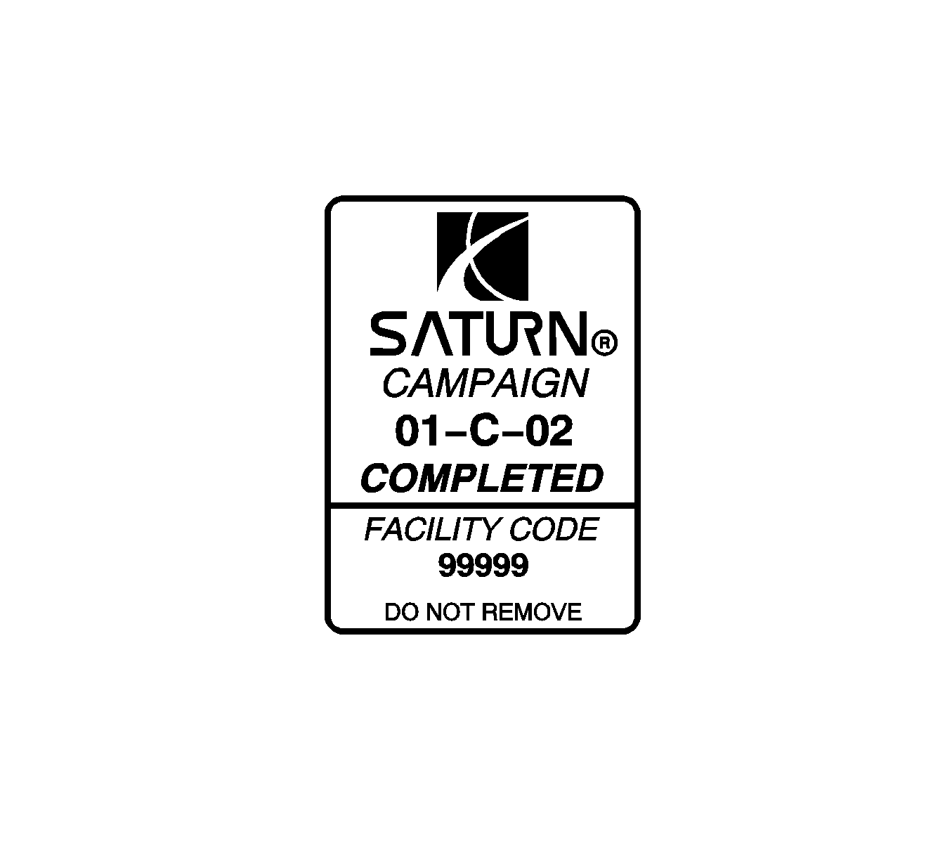
As a reminder, additional labels may be ordered from Saturn publications at 1-800-828-2112, prompt 3, Item #S03 00013A for the Campaign Completion Label, and item #S03 00013B for the Clear Protective Cover.
Credit
1. To receive credit for inspecting the fuel tank serial number and replacing the fuel tank, if necessary, submit a claim with the information below:
Repair Performed | Parts Allow. | Sale Type | Case Type | Labor Op. | Labor Hrs. | Admin. Hrs.** |
|---|---|---|---|---|---|---|
Top inspect the fuel tank serial number ADD: | * | WC | VC | V0585 | 0.2 | 0.1 |
a. To reposition strap to gain access to bar-code label OR | 0.2 | |||||
b. To inspect top of fuel tank for yellow mark | 1.3 | 0.1 | ||||
To inspect fuel tank serial number and replace fuel tank assembly | * | WC | VC | V0586 | 1.8 | 0.1 |
2. To receive credit for loaner/rental car costs incurred while owner awaits campaign repair or other goodwill expenses, submit a claim with the information below:
Repair Performed | Sale Type | Case Type | Labor Op. | Net Item Amount | Net Item Code | # Days Rental |
|---|---|---|---|---|---|---|
Loaner Disbursement | WC | VC | Z4123 | *** | C | **** |
Other Goodwill | WC | VC | Z4124 | *** | R | N/A |
3. Retailers are empowered to use good judgement regarding loaner/rental cars or any other goodwill expenses deemed necessary. It will not be necessary to call the Saturn Customer Assistance Center for authorization of goodwill. The Goodwill Worksheet (printed towards the back of this bulletin) must be used to document goodwill expenses. The completed Goodwill Worksheet must be attached to the hard copy of the CSO. Retailers are to make sufficient copies of the blank Goodwill Worksheet to document goodwill expenses.
4. Check your Saturn SERVICELINE.XL Claim Memorandum daily. Remember to code the claim as a WC sale type, and VC case type. Contact your field representative if you need assistance.
5. All labor operations claimed in this bulletin must be submitted on individual (unrelated) CSO lines . Refer to the Customer Service Order Preparation Manual for details on Product Campaign Claim Submission.
* The parts allowance should be the sum total of the current SSPO Retailer net price plus 30 percent of all parts required for the repair.
** Campaign administrative allowance
*** Net amount must be submitted as a miscellaneous sale. Loaner reimbursement not to exceed $30 per day.
**** Enter number of days vehicle was rented (not to exceed 1 day).
01-C-02 GOODWILL WORKSHEET
As stated in the Credit section of this bulletin, Retailers are empowered to use good judgement regarding loaner/rental cars or other goodwill expenses that might become necessary for customer satisfaction.
Complete this worksheet and attach it to the hard copy of the Customer Service Order (CSO) to document all campaign goodwill claims submitted to Saturn.
VIN #
A. Vehicle Loaner/Rental Allowance Explanation: | $ | ||||
| |||||
| |||||
| |||||
Repair Performed | Sale Type | Case Type | Labor OP | Net Item Code | # Days Rental |
Loaner Reimbursement | WC | VC | Z4123 | C | * |
* Not to exceed $30/day for 1 day | |||||
| |||||
| |||||
| |||||
B. Other/Goodwill Allowance Explanation (Specify what was done and why): | $ | ||||
| |||||
| |||||
| |||||
Repair Performed | Sale Type | Case Type | Labor OP | Net Item Code | # Days Rental |
Other Goodwill | WC | VC | Z4124 | R | N/A |
| |||||
| |||||
| |||||
Authorized Retailer Signature | |||||
(Please copy this form as necessary) | |||||
Dear Saturn Owner:
This notice is sent to you in accordance with the requirements of the National Traffic and Motor Vehicle Safety Act.
Saturn has decided that certain 2000 and 2001 S-Series Saturn vehicles fail to conform to the requirements of Federal Motor Vehicle Safety Standard (FMVSS) 301, "Fuel System Integrity." Some vehicles have been produced with an inadequate vent valve weld on the top portion of the fuel tank. Fuel spillage could occur during refueling or if a vehicle were involved in a rollover. If an ignition source were present, a fire could result.
To prevent the possibility of this occurring, Saturn Retailers will inspect, and, if necessary, replace the fuel tank assembly.
What Saturn will do
To ensure that the fuel tank vent valve is properly welded, Saturn will inspect the fuel tank serial number and replace the fuel tank assembly if necessary. This service will be performed at no charge to you. It will take approximately two (2) hours to make the repairs, although some additional time may be required for paperwork and processing.
What you should do
Contact your Saturn Retailer to arrange to have this service performed.
Your Retailer is prepared to perform this service promptly and with minimal inconvenience to you. Should your Retailer be unable to schedule a service date within a reasonable time, please contact the Saturn Customer Assistance Center at 1-800-553-6000 prompt 3, or for the hearing impaired, 1-800-833-6000. We will assist you and the Retailer in getting your car serviced.
If, after contacting your Saturn Retailer and the Saturn Customer Assistance Center, you are still not satisfied we have done our best to remedy this condition without charge and within a reasonable time, you may wish to write the Administrator, National Highway Traffic Safety Administration, 400 Seventh St., SW, Washington, DC 20590, or call 1-800-424-9393 (Washington, DC residents use 202-366-0123).
Again, we sincerely regret any inconvenience or concern this situation may cause you. We want you to know that we will do our best, throughout your ownership experience, to ensure that your Saturn provides you many miles of enjoyable driving.
Sincerely,
Saturn Corporation
01-C-02
