Camshaft Replacement SOHC
Tools Required
SA9124E Valve Spring Compressor/Remover
Removal Procedure
- Remove battery cover and battery. Refer to Battery Replacement .
- Refer to Cylinder Head Removal for procedures on removing the rocker cover, front cover assembly, timing gears, timing chain, and timing chain guides.
- Remove rocker arms and lifter assemblies.
- Drive camshaft plug inward and remove from cylinder head with a magnet.
- Remove camshaft out of the rear of the cylinder head.
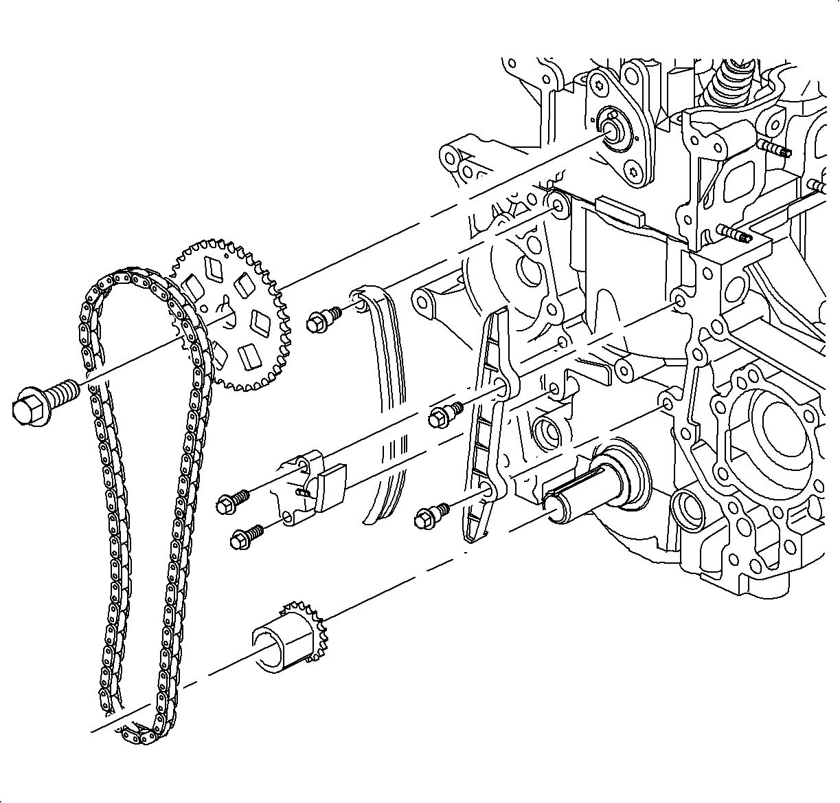
Important: Lifters, valve springs, caps, and stem seals can be replaced without removing the cylinder head, using the SA9124E . The camshaft can be removed through the cylinder head rear plug hole. Front cover assembly and timing chain/gear removal are required.
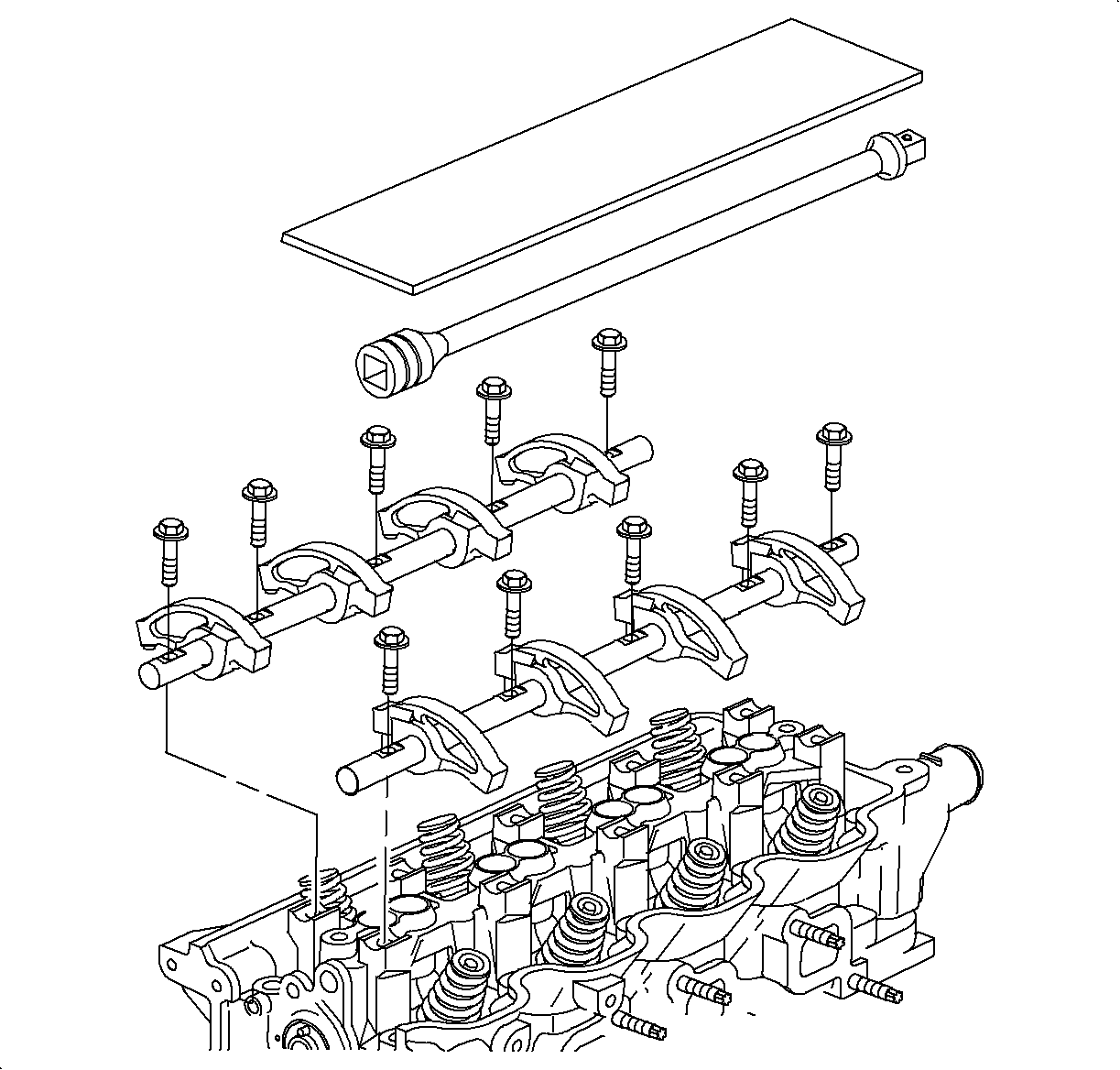
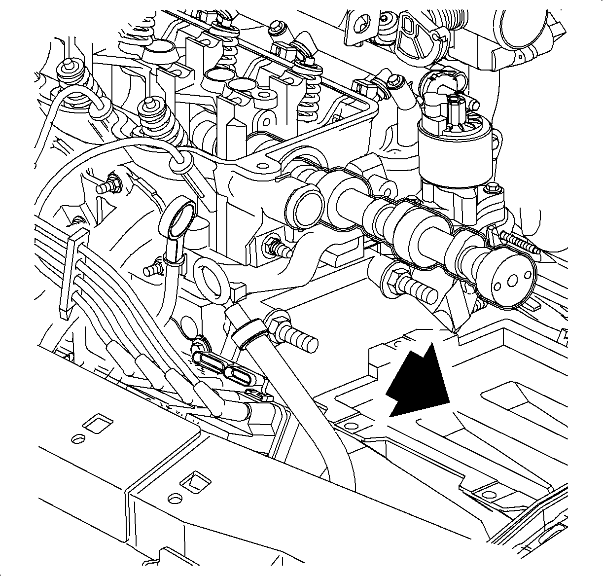
Important: The rear camshaft plug hole is oversize to allow for camshaft removal in-vehicle.
Installation Procedure
- Install camshaft in rear of the cylinder head.
- Coat a new rear cylinder head plug with Saturn P/N 21485277 Loctite 242® (or equivalent) and install it using a standard bushing driver.
- Refer to Camshaft Timing Chain, Sprocket, and Tensioner Installation and to Engine Front Cover Replacement for procedures on installing the timing gears, timing chain, timing chain guides, tensioner, front cover assembly and rocker cover.
- Install battery and tighten battery hold-down nut and screw.
- Install the battery cables.

Tighten
Tighten the battery hold down nut to 9 N·m (80 lb in).
Tighten
Tighten the battery terminal bolts to 17 N·m (13 lb ft).
Camshaft Replacement DOHC
Tools Required
J 43299 Camshaft Holder
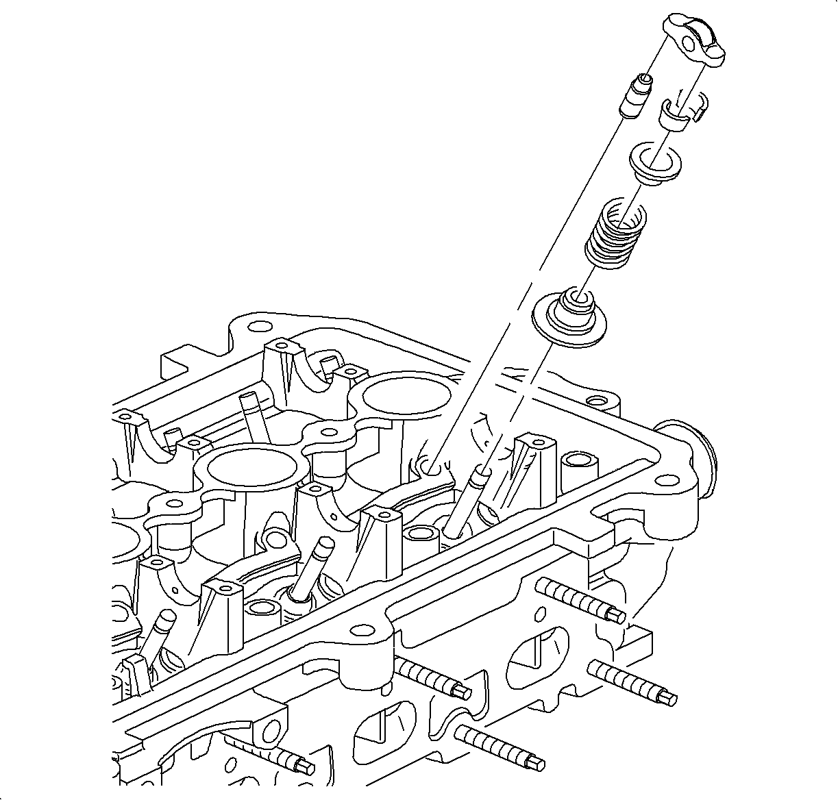
Important: TheJ 43299 Camshaft Holder must be used to remove one or both camshafts at the same time. The engine's crankshaft can not be rotated with the camshafts removed.
The DOHC (LL0) engine's camshafts, lash adjusters, valve springs, and seals can be serviced without removing the engine's exhaust system, vibration damper, front mount, and front cover. The following procedure must be followed to prevent damage to the camshafts, lash adjusters, cylinder head, and timing chain guides.
Removal Procedure
- Remove the upper mount to front cover. This is required to enable a torque wrench to be used to assemble camshaft sprocket bolts in later steps.
- Remove the spark plug wires, accessory drive belt, the PCV fresh air hose, and cam cover assembly.
- Locate the piston in the No. 1 cylinder at top dead center (intake and exhaust valves closed). Align the mark on the damper with the arrow mark on the front cover as shown. It may be necessary to remove the right-hand road wheel and splash shield to observe timing marks on front cover and crankshaft vibration damper.
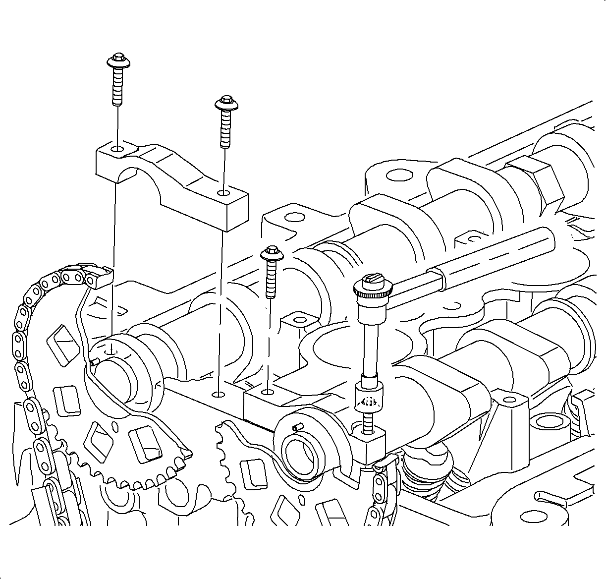
- Remove both front camshaft bearing caps.
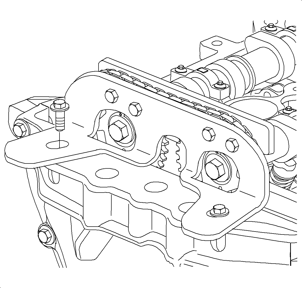
- Assemble the rear camshaft support fixture to the back side of the camshaft sprockets.
- Assemble the front camshaft support fixture to the rear camshaft support fixture with four bolts.
- Install and tighten the two 6 mm hex bolts that attach the front support fixture to the front engine cover.
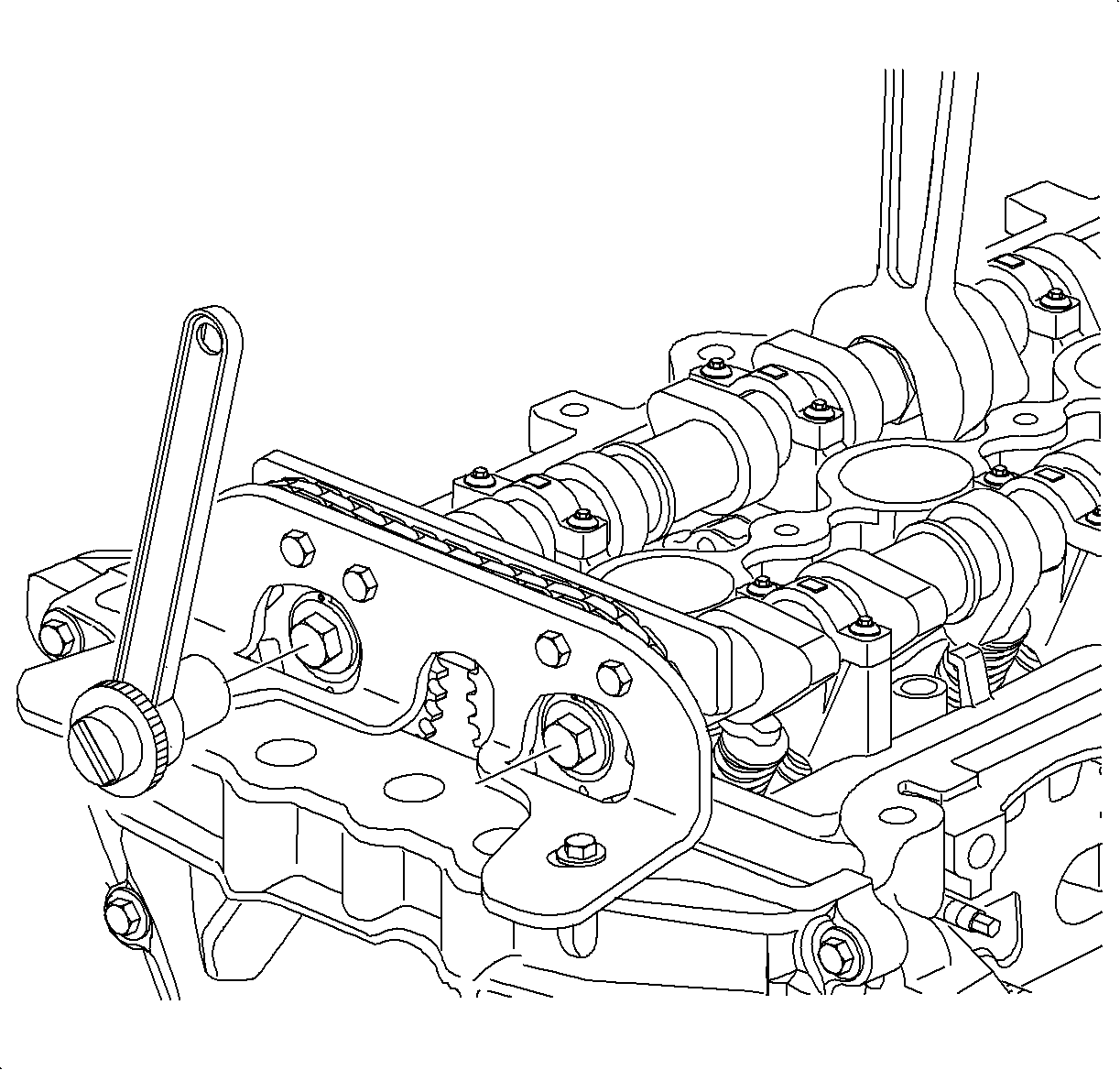
- Hold each camshaft in place using a 24 mm open end wrench and carefully remove the camshaft timing sprocket retaining bolts and washers.
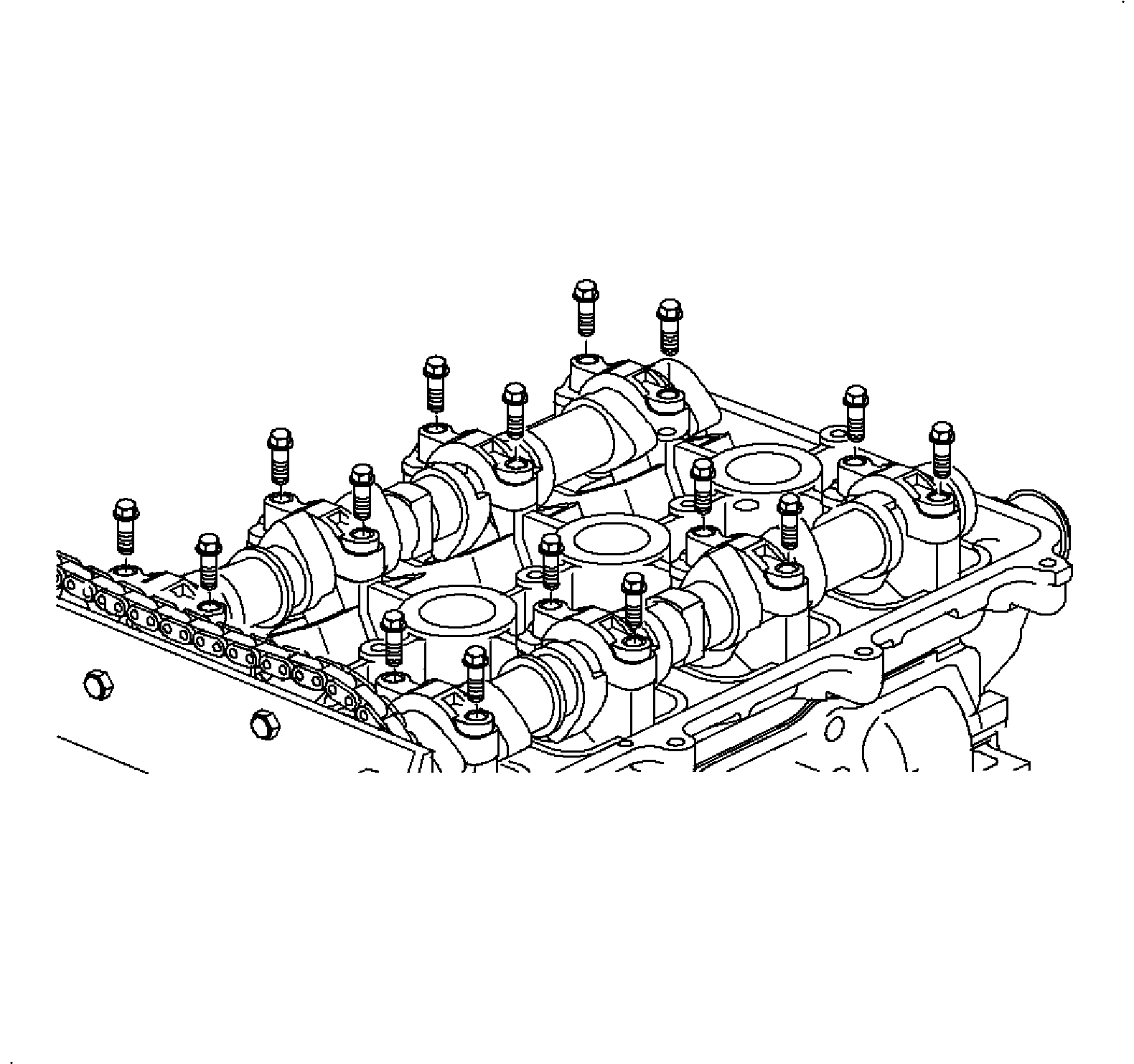
- Uniformly loosen and remove the rest of the camshaft bearing cap bolts in several passes.
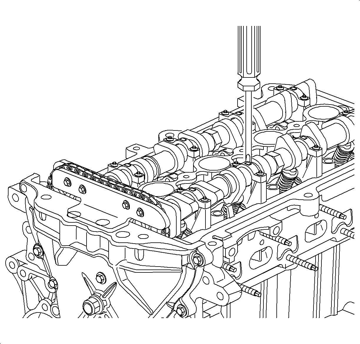
- Move the camshafts rearward by prying between the side of the camshaft lobe and the camshaft bearing journal. Use care to avoid scratching the machined camshaft surface. Remove the camshafts.
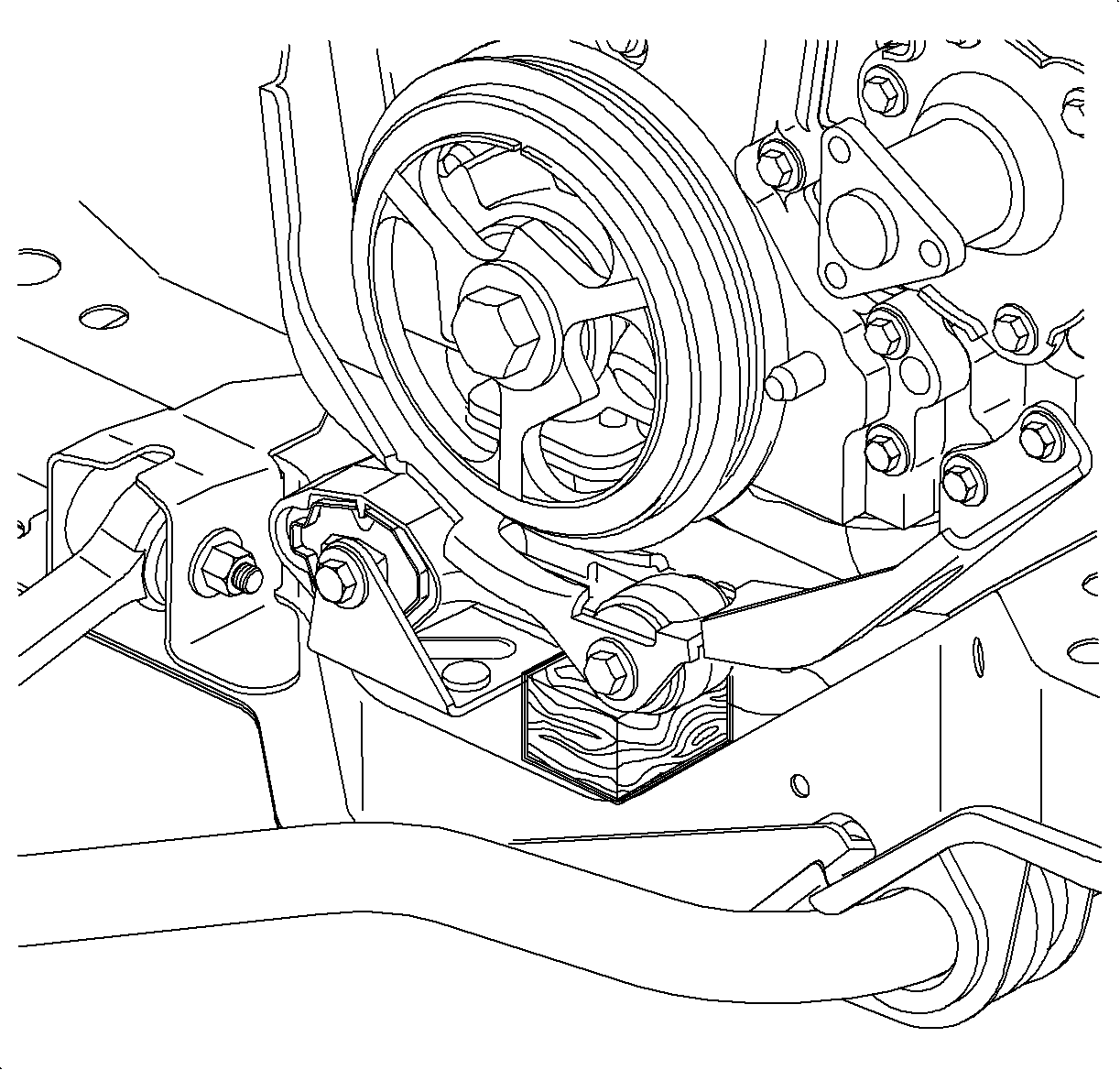
| 1.1. | Unclip the lower splash shield attachment clips and place a 1 in. x 1 in. x 2 in. block of wood between the torque strut and cradle. |
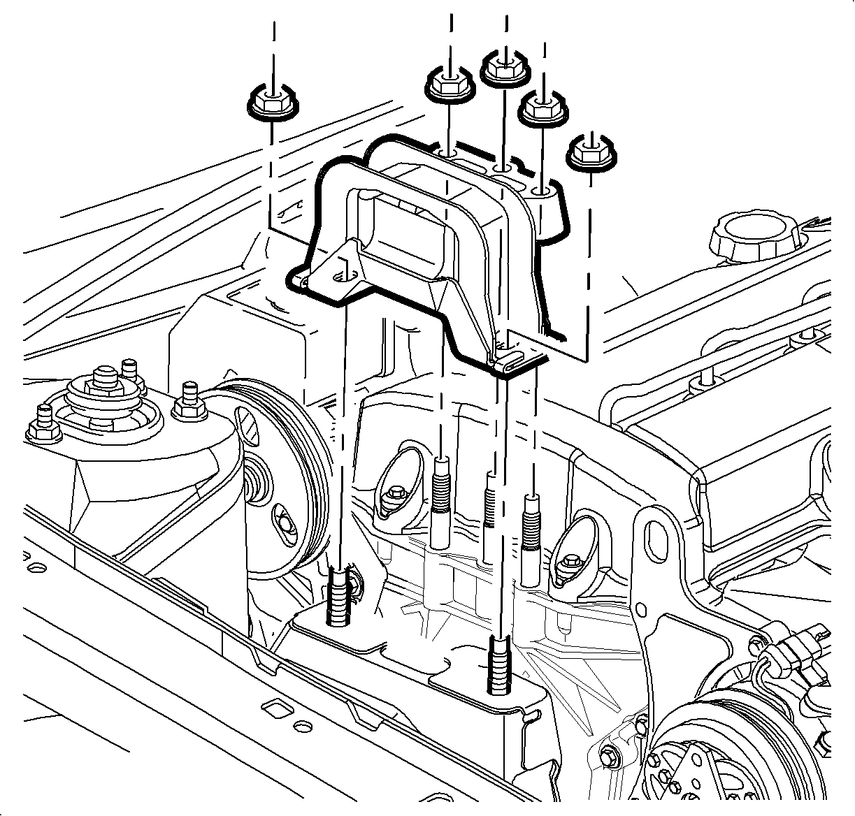
| 1.2. | Remove the three right-hand upper engine torque axis mount to front cover nuts and the two mount to midrail bracket nuts, allowing the powertrain to rest on the block of wood, and remove the mount. |
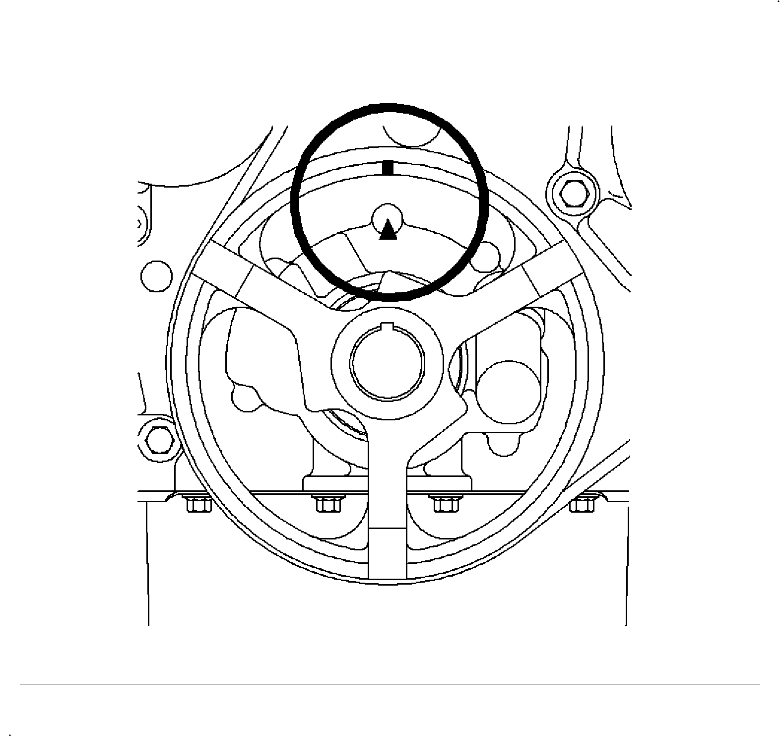
Notice: The engine must have the No. 1 cylinder piston at top dead center (TDC) when removing and installing camshafts or the timing chain, gears and chain guides will be damaged when air pressure is put into the cylinder to hold the valves closed.
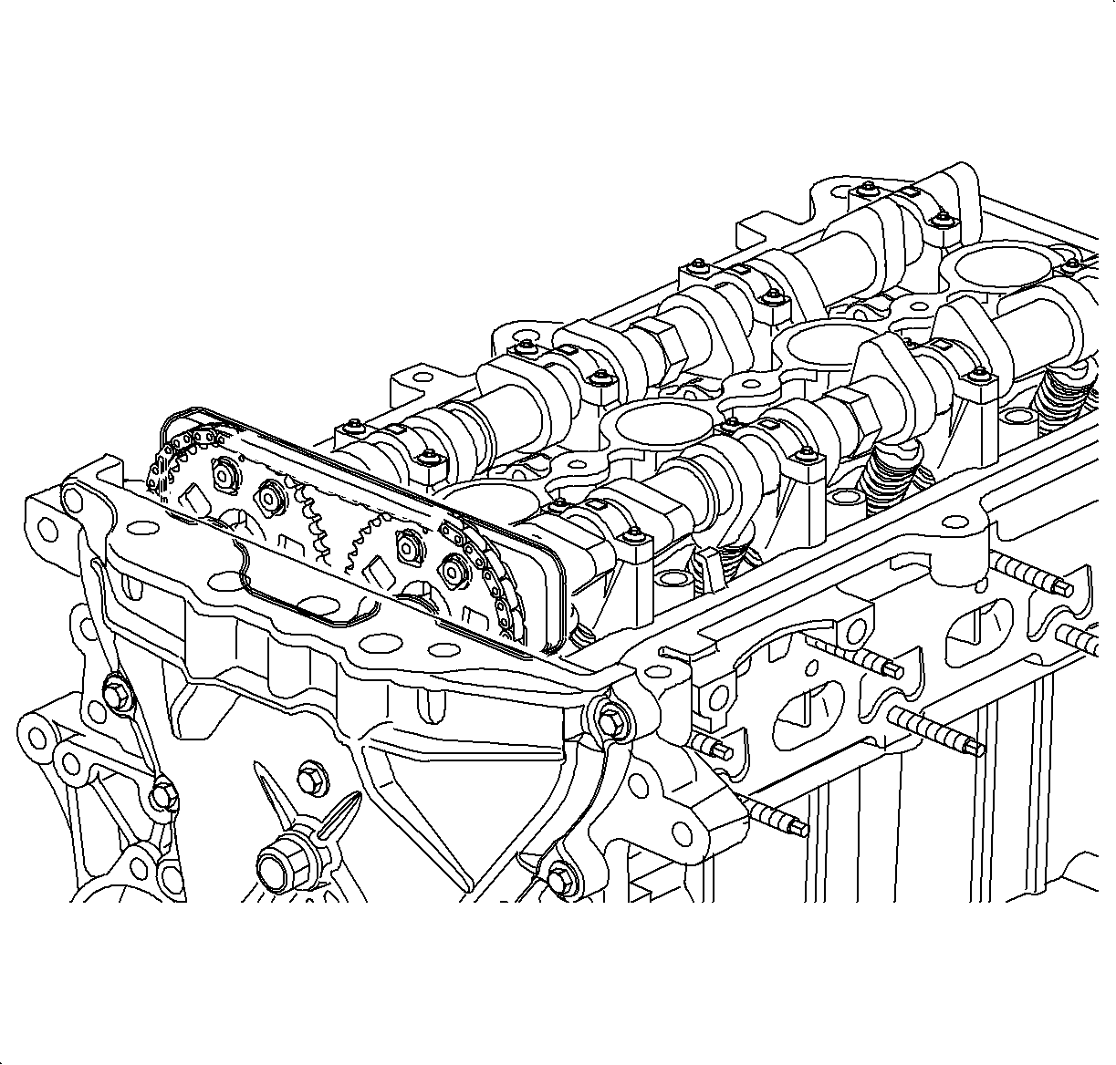
Important: Both camshaft dowel pins will be located at the 12 o'clock position and timing pin holes in camshaft sprockets will be aligned when engine cylinder No. 1 is at TDC.
Tighten
Tighten the bolts 25 N·m (19 lbs ft).
Tighten
Tighten the bolts 10 N·m (89 lbs in).
Installation Procedure

| Important: Camshafts and caps are marked for proper installation. If camshafts are installed at the wrong locations the following will occur: |
| • | The oil baffles in the cam cover will interfere with the camshafts and the cam cover will not assemble properly. Noise will be evident upon engine operation. |
| • | DTC P0172 (System Rich) is likely to set. |
| • | Poor engine performance at throttle tip-in will be evident. |
- Lubricate the camshaft bearing journals with clean engine oil and install both camshafts and all bearing caps, except the front cap on each camshaft. Tighten down the bearing cap bolts uniformly.
- Install the camshaft sprocket pilot bolts (one in each camshaft) and tighten. This will pull the camshaft fully forward.
- Remove the four bolts that assemble the front camshaft holding fixture to the rear camshaft holding fixture. Remove both fixtures.
- Install the two remaining camshaft bearing caps.
- Install cam cover assembly, PCV/fresh air hoses, accessory drive belt, EGR, and spark plug wires
- Install the two mount to midrail bracket nuts first. Next, install the three front upper mount to engine front cover nuts. Remove the block of wood from under the torque strut after the upper mount assembly is installed.
Tighten
Tighten the Camshaft Bearing Cap-to-Head (LL0) 14 N·m (10 lbs ft).
Tighten
Tighten the Camshaft Sprockets-to-Camshafts 100 N·m (74 lbs ft).
Tighten
Tighten the Camshaft Bearing Cap-to-Head (LL0) 14 N·m (10 lbs ft).
Important: Verify camshafts are properly timed as outlined in this section prior to starting engine.
Notice: To prevent engine front cover and mount damage, the three engine mount to engine front cover nuts must be tightened down uniformly.
Tighten
Tighten the Engine Mount-to-Front Cover Nuts 50 N·m (37 lbs ft).
Tighten
Tighten the Engine Mount-to-Midrail Bracket Nuts 50 N·m (37 lbs ft).
