Removal Procedure
- Ensure that the fuel level in the tank is not greater than half. If necessary, drain the fuel tank to at least this level. Refer to Fuel Tank Draining .
- Position on the hoist.
- Disconnect the negative battery cable
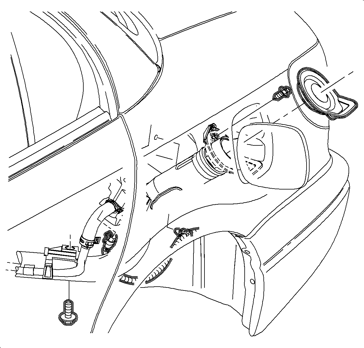
- Remove the fuel filler cap and rubber closeout grommet around the fuel filler pipe neck, inside the fuel filler door.
- Remove the attachment screw (T-30) at the upper end of the filler pipe.
- Raise the vehicle to a comfortable working position.
- Remove the wheel house inner liner.
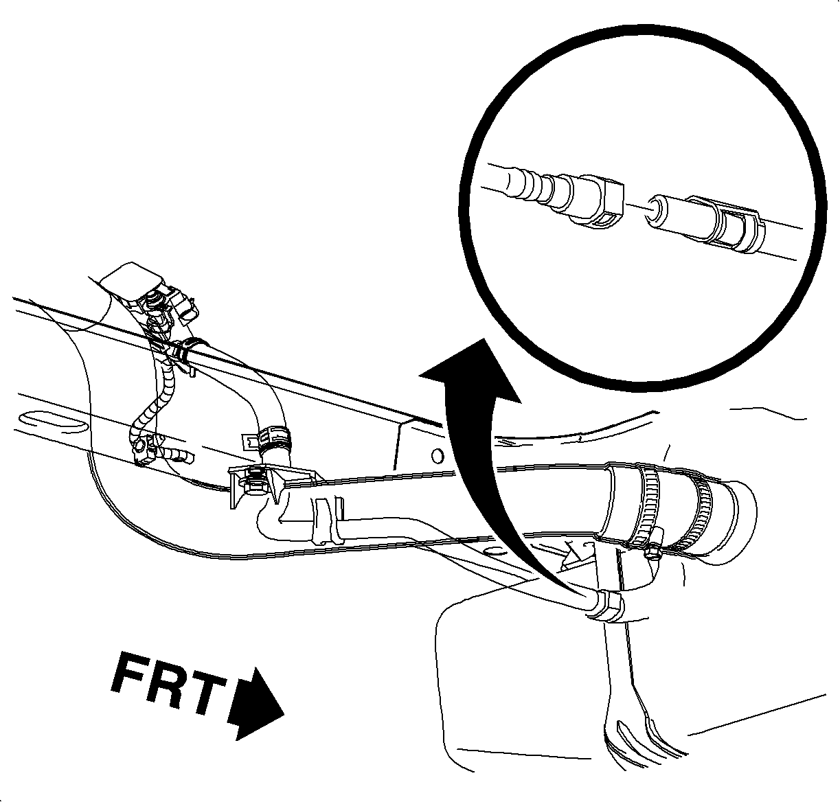
- Disconnect the wiring harness connector at the evaporative emission (EVAP) canister vent solenoid.
- Remove the fuel filler pipe lower bracket attachment screw (10 mm hex) at the underbody left-hand side rail.
- Disconnect the EVAP canister vent hose at the quick connect to the canister vent hose.
- Loosen the fuel filler pipe hose clamp (7 mm hex) closest to the fuel tank.
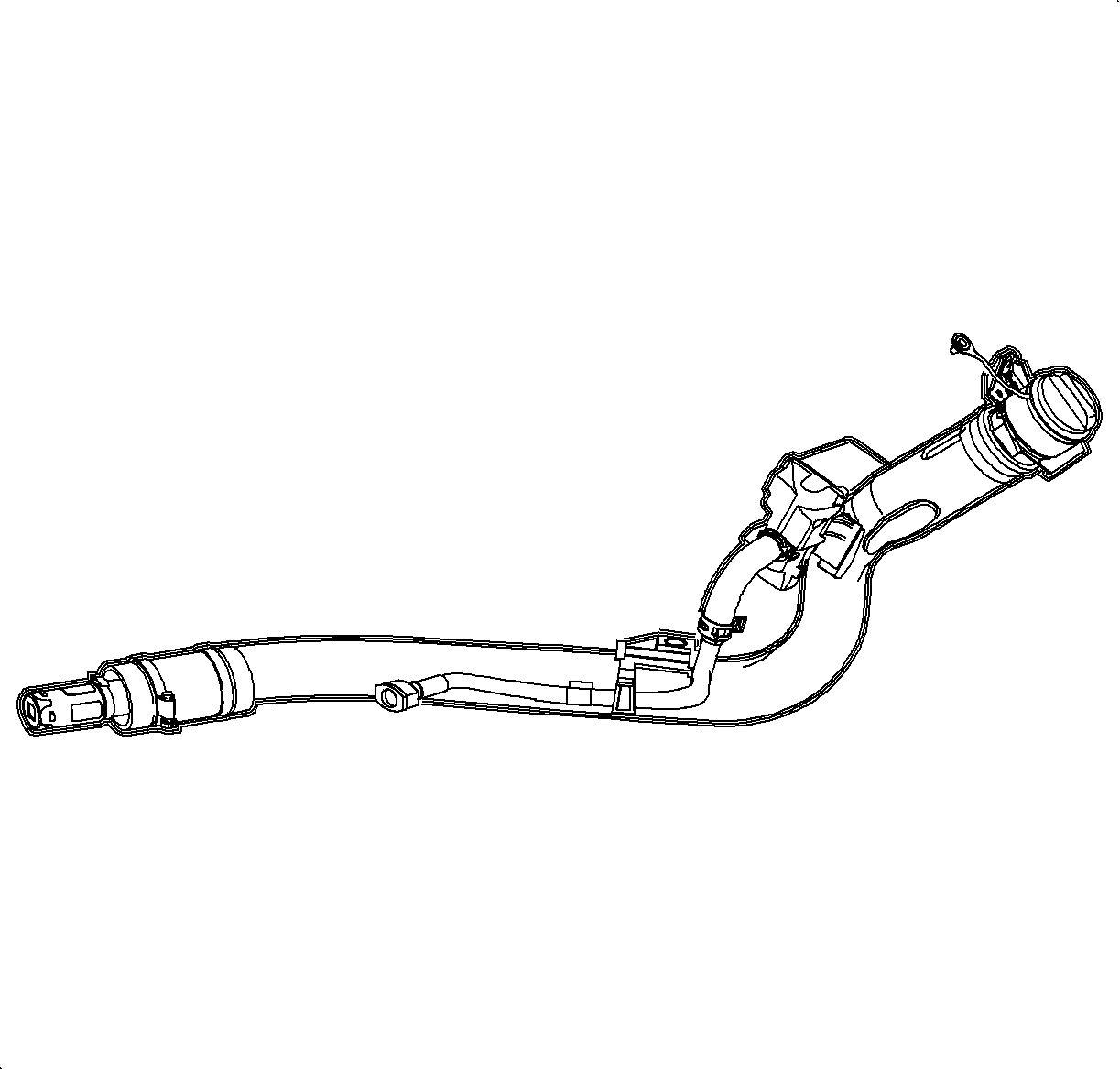
- Disengage the filler pipe hose from the fuel tank and remove the fuel filler pipe.
- Perform the Service Bay Diagnostic Test for the evaporative emission system using the Tech-2. This test will verify the integrity of the vapor handling areas of the fuel system. Refer to Service Stall System (SSS) user guide.


Caution: Several ounces of gasoline may remain in the fuel filler pipe due to the design of the inlet check valve. Be aware of this when handling the filler pipe during removal from the fuel tank. Surround the check valve body with a shop cloth held in place with your hand. Have a suitable container available and drain any fuel by unseating the check valve.
Important: To provide space to remove the filler pipe, guide the top of the filler pipe into the quarter panel opening while removing the fuel filler pipe.
Notice: Keep fuel filler pipe as straight and level as possible when removing it from the tank. Fuel fill check valve clamp may drag on the inlet neck of the tank and care should be used in removing it. If valve is dislodged from filler pipe it may remain in the tank.
Installation Procedure
- Raise the vehicle to a comfortable working height.
- Ensure that the fuel filler check valve is in place at the end of the fuel filler pipe.
- Position the filler pipe into the wheel opening with the top of the pipe within the body panel opening.
- Install the fuel filler pipe into the fuel tank opening.
- Loosely install the filler pipe lower bracket attachment screw, 10 mm hex, but do not tighten.
- Lower the vehicle and install the filler pipe upper bracket attachment screw, T-30.
- Install the rubber closeout grommet to body and filler.
- Install the fuel cap.
- Raise the vehicle to a comfortable working height.
- Tighten the hose clamp, 7 mm hex, on the filler pipe to the fuel tank connecting hose.
- Connect the EVAP canister vent pipe at the quick connect to the canister vent hose.
- Tighten the lower attachment screw on the filler pipe to the underbody.
- Connect the wiring harness to the EVAP vent solenoid.
- Install the wheelhouse inner liner to the wheel opening.

Important: To ease installation, lightly wipe the outside of the fuel tank inlet connector with plain water.
Notice: Refer to Fastener Notice in the Preface section.

Important: Ensure that the EVAP vent solenoid pipe is installed in position on the filler pipe bracket.
Tighten
Tighten the fuel tank fill pipe-to-upper bracket tscrew to 3.5-4.5 N·m
(31-39 lb in).

Important: Ensure that the fuel pipe connecting hose is installed to within 6 mm (1/4 in) of the stops on the fuel tank inlet connector. The hose clamp should be located within 4 mm (3/16 in) of the end of the connecting hose.
Tighten
Tighten the fuel tank fill hose-to-clamp to 3.5-4.5 N·m (31-39 lb in).
Tighten
Tighten the fuel tank fill pipe-to-underbody rail to 8 N·m (71 lb in).
