The powertrain control module (PCM) monitors the following evaporative emission
(EVAP) system electrical components for low and high voltage faults.
| • | Fuel tank pressure sensor |
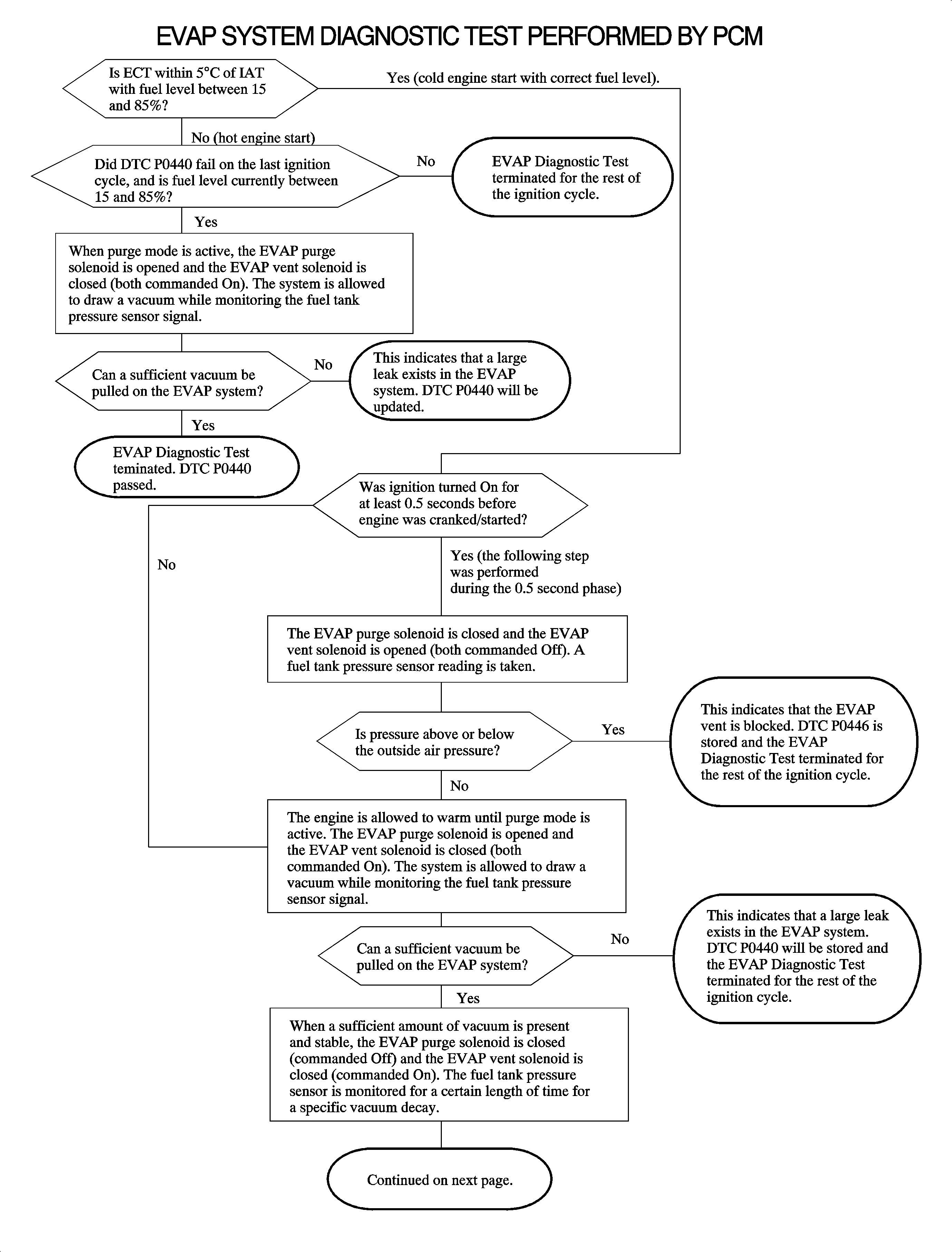
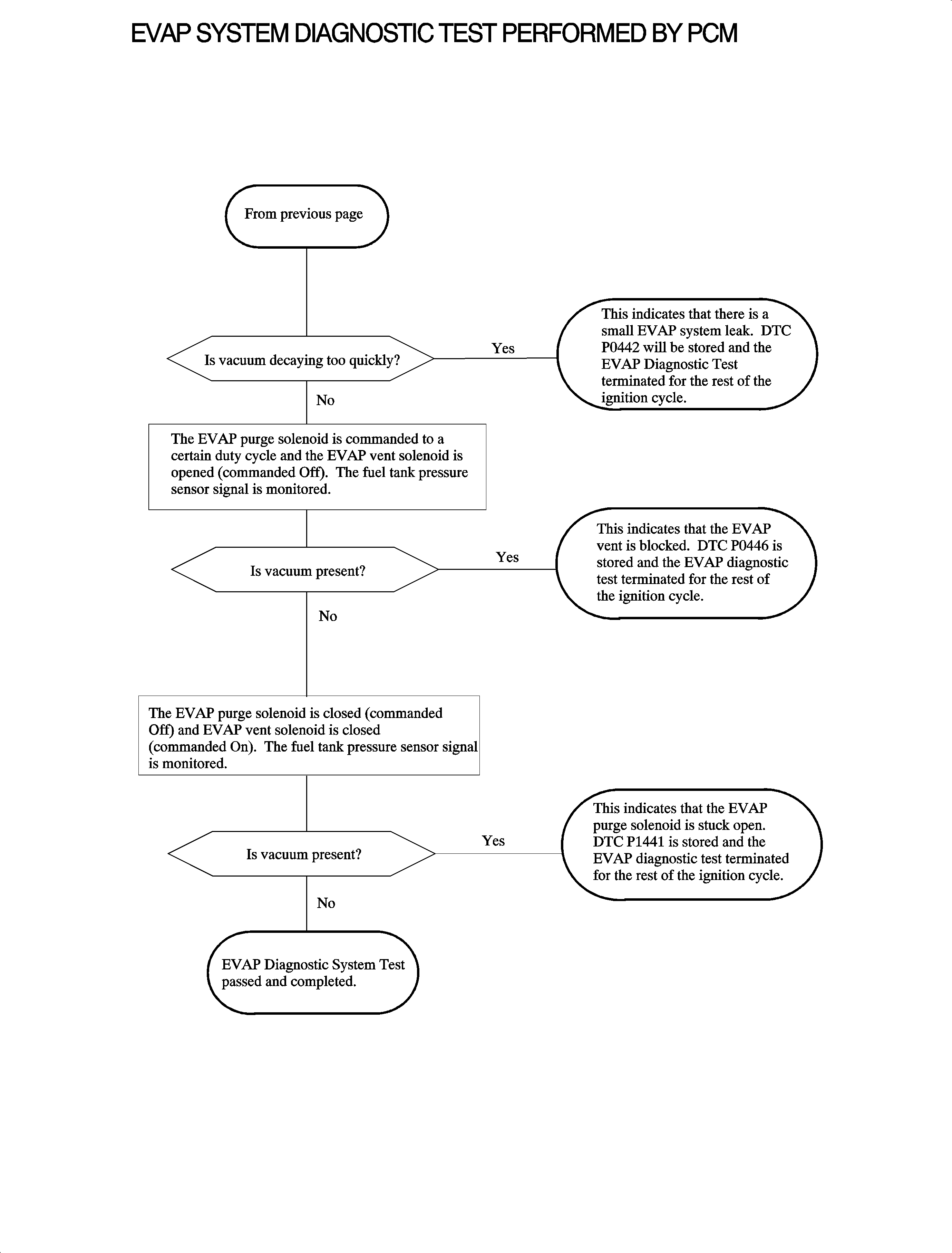
Important: The following flowchart consists of a series of tests run by the PCM which describes
the entire EVAP DIAGNOSTIC TEST. Each step the PCM performs is dependant on the accuracy
of the fuel tank pressure sensor. The FUEL TANK PRESS. SENSOR reading on scan tool
with ignition ON, engine OFF and fuel cap removed should read between 1.3-1.7 volts.
The EVAP SERVICE BAY TEST on the scan tool is nearly identical to the following
ON-board test. Performing the EVAP SERVICE BAY TEST simply forces the PCM to run
the ON-board test regardless if operating conditions have been met.
As part of the ON-board diagnostics second generation (OBD II) requirements,
the government mandates that all automobile manufactures detect a 0.02 inch
or greater diameter leak in the EVAP system (for 2000 model year, the PCM
will detect a 0.04 in leak). To comply, the PCM monitors the EVAP system for
large and small leaks and whether the EVAP purge and vent solenoid valves are stuck
closed or open.


Diagnosing a Fault in the EVAP System
When the malfunction indicator light (MIL) is commanded ON and an EVAP DTC is
set, there are certain ordered steps that should be taken to ensure correct diagnosis.
- Diagnose any hard circuit fault fuel tank pressure sensor (
DTC P0452
or
DTC P0453
), EVAP purge
solenoid (
DTC P0444
or
DTC P0445
)
or EVAP vent solenoid (
DTC P0447
or
DTC P0448
)
DTCs first. These types of DTCs are probably the cause of other non-hard circuit fault
EVAP DTCs.
- Ensure the fuel level is between 15-85 percent and fuel
gage reads correctly.
- Using a scan tool, monitor FUEL TANK PRESS. SENSOR with the ignition ON,
engine OFF and fuel cap removed. The voltage should be between 1.3-1.7 volts.
- Reinstall the fuel cap.
- Using a scan tool, perform the EVAP SERVICE BAY TEST to verify the system
has failed.
| • | If EVAP LARGE LEAK fails, diagnose using
DTC P0440 |
| • | If EVAP SMALL LEAK fails, diagnose using
DTC P0442 |
| • | If EVAP VENT BLOCKAGE fails, diagnose using
DTC P0446 |
| • | If EVAP PURGE VALVE LEAK fails, diagnose using
DTC P1441 |
| • | If the EVAP SERVICE BAY TEST passed, refer to the Diagnostic Aids section of
the initial individual DTC that set to help locate a problem. |
- A leak in the system must be present, if the EVAP SERVICE BAY TEST failed.
The test is the same test the PCM performs in the previous flowchart, however, the
enable criteria is by-passed. Use the EVAP PRESSURE/PURGE DIAGNOSTIC CART TEST PROCEDURE
to locate the leak.
EVAP Pressure/Purge Diagnostic Cart Test Procedures
Important: Make sure the fuel tank is 85 percent full or less. If fuel level is
greater than 85 percent drain fuel down to 85 percent full. Refer to
Fuel Tank Draining
in this service manual.
- Ignition ON, engine OFF.
- Using a scan tool, command EVAP SYSTEM SEAL ON.
- Connect the red hose from the EVAP Pressure/ Purge Diagnostic Station
to the EVAP service port. Be sure to finger tighten to prevent damage to the internal
hose seal or EVAP service port.
- Open the nitrogen cylinder valve and adjust pressure to 30 inches
of H20.
- Turn the control panel rotary valve to the pressure position.
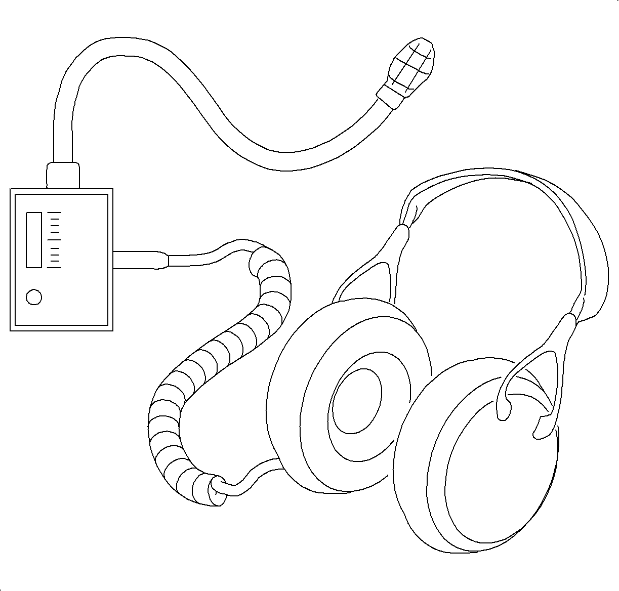
- Use the J 41416
Ultrasonic
Leak Detector to locate leak.
Notice: The Ultrasonic Leak Detector should be held as close to the test area as safely
as possible. Check around all hoses and connections using a zig-zag motion, carefully
covering all suspected areas. If there is no ultrasonic sound present, the display
will not show any lights. When an ultrasonic signal is detected, it will be indicated
by an increase in the LED meter and an accompanying translation in audio in the headset.
A leak will produce a rushing sound in the headset. The sound will become more intense
and meter reading will increase as the instrument is drawn closer to the leak point.

- Close the nitrogen cylinder valve.
- Turn the rotary valve to the pressure release position.
- Allow adequate time for the EVAP pressure gage to return to zero inches
of H2O.
- Turn the rotary valve to the OFF/Hold position.
- Disconnect the red hose from the service port.
Notice: Do not attempt any fuel system servicing when the fuel system is pressurized.
The rotary valve must be in the Off/Hold position and all nitrogen pressure must be
depleted from the fuel system prior to removal of the fuel cap or disassembly of any
fuel system component.
- Repair any leaking components.
- Using the scan tool, run the EVAP SERVICE BAY TEST to verify repair.


