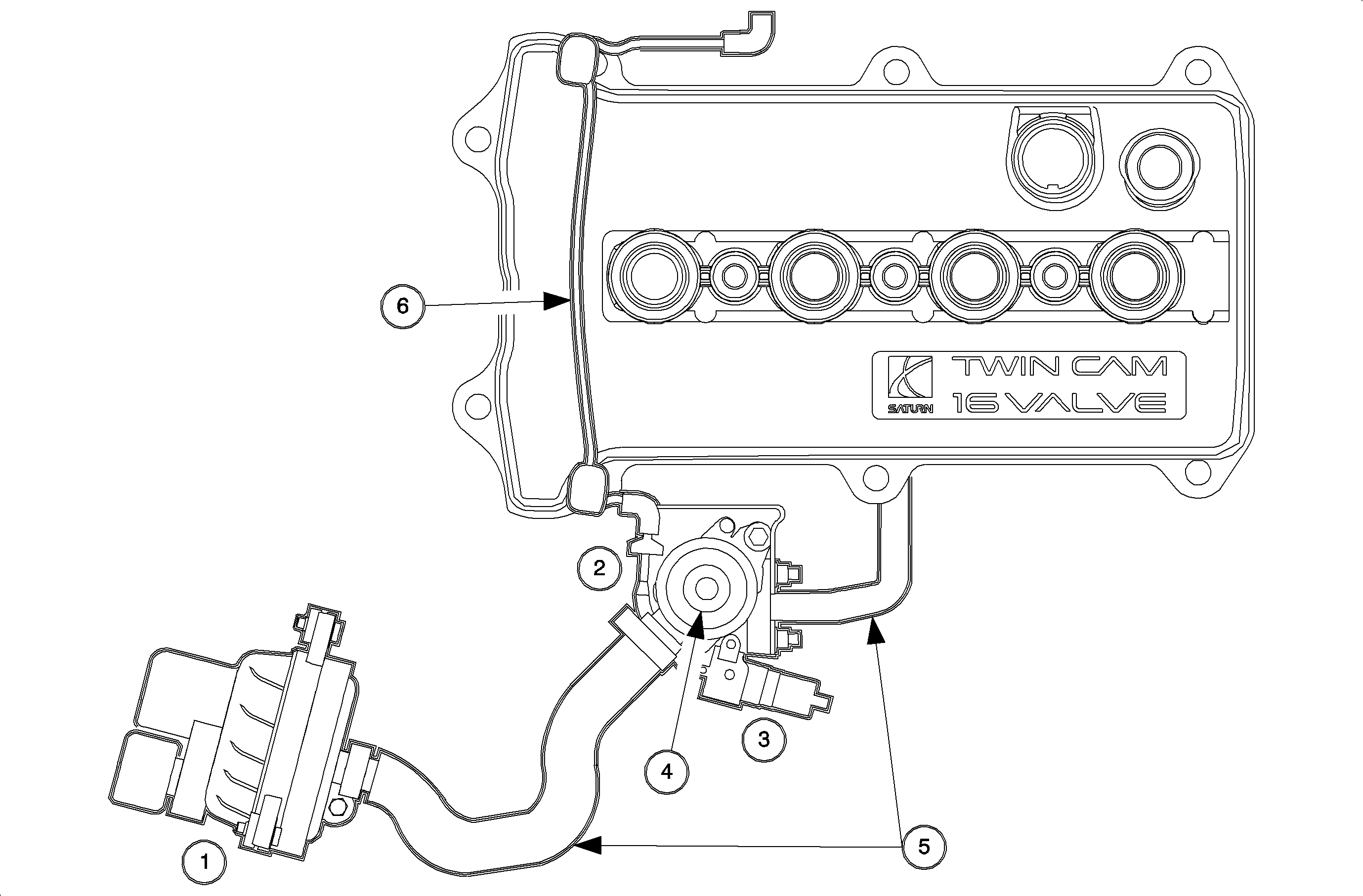
Air System Operation
The AIR system is used to reduce hydrocarbons (HC), carbon monoxide (CO) and oxides of nitrogen (NOX) exhaust emissions by heating up the catalytic converters quicker on cold engine start-up. The conversion of exhaust emissions to carbon dioxide (CO2) and water can occur sooner as the catalytic converter reach the normal operating temperature around 527°C (981°F). The AIR system consists of:
| • | Air pump (1) |
| • | Check valve (2) |
| • | Air pump solenoid (3) |
| • | Combination valve (4) |
| • | Air pipe and hose (5) |
| • | Vacuum hose (6) |
| • | Air pump relay - located in underhood fuse block (UHFB). (7) |
| • | Powertrain control module (PCM) - located underhood between the battery and power brake booster. (8) |
The air pump is a permanently lubricated turbine type pump which requires no periodic maintenance. The PCM runs the air pump for a certain length of time when the engine is started within a certain ECT range. When the air pump is commanded ON, the PCM will command an internal driver ON which pulls the air pump relay circuit to ground allowing current to flow to the air pump.
The air pump solenoid is used to control vacuum to the combination valve. When the air pump relay is commanded ON, air pump running), the PCM will wait a short amount of time to command the air pump solenoid ON. The PCM turns the solenoid ON by controlling an internal driver that pulls the solenoid circuit to ground. The PCM waits to turn the solenoid ON in order for the air pump to pressurize which keeps exhaust gas from entering the air pump.
When the air pump and air pump solenoid are turned ON, vacuum to the combination valve will allow the spring loaded diaphragm, upper valve in the combination valve, to be pulled up. This will allow pressurized air from the air pump to flow around the reed valve, lower valve in combination valve, to the exhaust manifold.
Before the PCM commands the air pump relay OFF, it will first command the air pump solenoid OFF and wait a short amount of time before it commands the relay OFF. This keeps exhaust gas from entering the air pump.
Air System Enable Criteria
| • | The traction control is not active. |
| • | The battery voltage is between 11-18 volts. |
| • | The ECT is between 4-79°C (40-174°F). |
| • | The IAT is greater than 0°C (32°F). |
| • | The engine speed is less than 3,200 RPM. |
| • | The MAP is greater than 20 kPa. |
| • | The calculated engine airflow is less than 30 g/s. |
Engine Coolant Temperature | Air Pump Run Time | |
|---|---|---|
(°F ) | (°C ) | seconds |
24 | -4 | 35-65 |
46 | 8 | 35-60 |
68 | 20 | 35 |
96 | 32 | 35 |
111 | 44 | 35 |
133 | 56 | 30 |
154 | 68 | 20 |
176 | 80 | 10 |
198 | 92 | 0 |
Air System Diagnostics
During the AIR system diagnostic (DTC P0410), the PCM will use the oxygen sensor 1 (O2S-1) to verify the AIR system is working. When the PCM commands the AIR system to run, the O2S-1 signal should indicate a lean condition due to outside air being pumped into the exhaust manifold. If the PCM does not detect a certain lean O2S-1 signal after a series of tests, DTC P0410 will set.
