Throttle Linkage Inspection Procedure
- The throttle system, includes accelerator and cruise, should operate freely without hesitation between full closed and wide open throttle. Throttle system components causing hesitation or sticking should be replaced. Inspect for the following:
- Replace missing or damaged components. Reroute any misrouted components.
| • | Missing parts such as retainers or clips |
| • | Interference of linkage or cable conduit to critical components such as fuel lines, brake pipes, harness leads, etc. |
| • | Proximity of cable to exhaust system and other heat sources -- check for melting and/or discoloration. |
| • | Cable kinking, maintain generous bend radii of cables |
| • | Clearance of throttle system moving parts throughout their travel relative to stationary components |
| • | Damage of components due to cable kinking, severe abrasion, misalignment, frayed core wire, etc. |
Removal Procedure
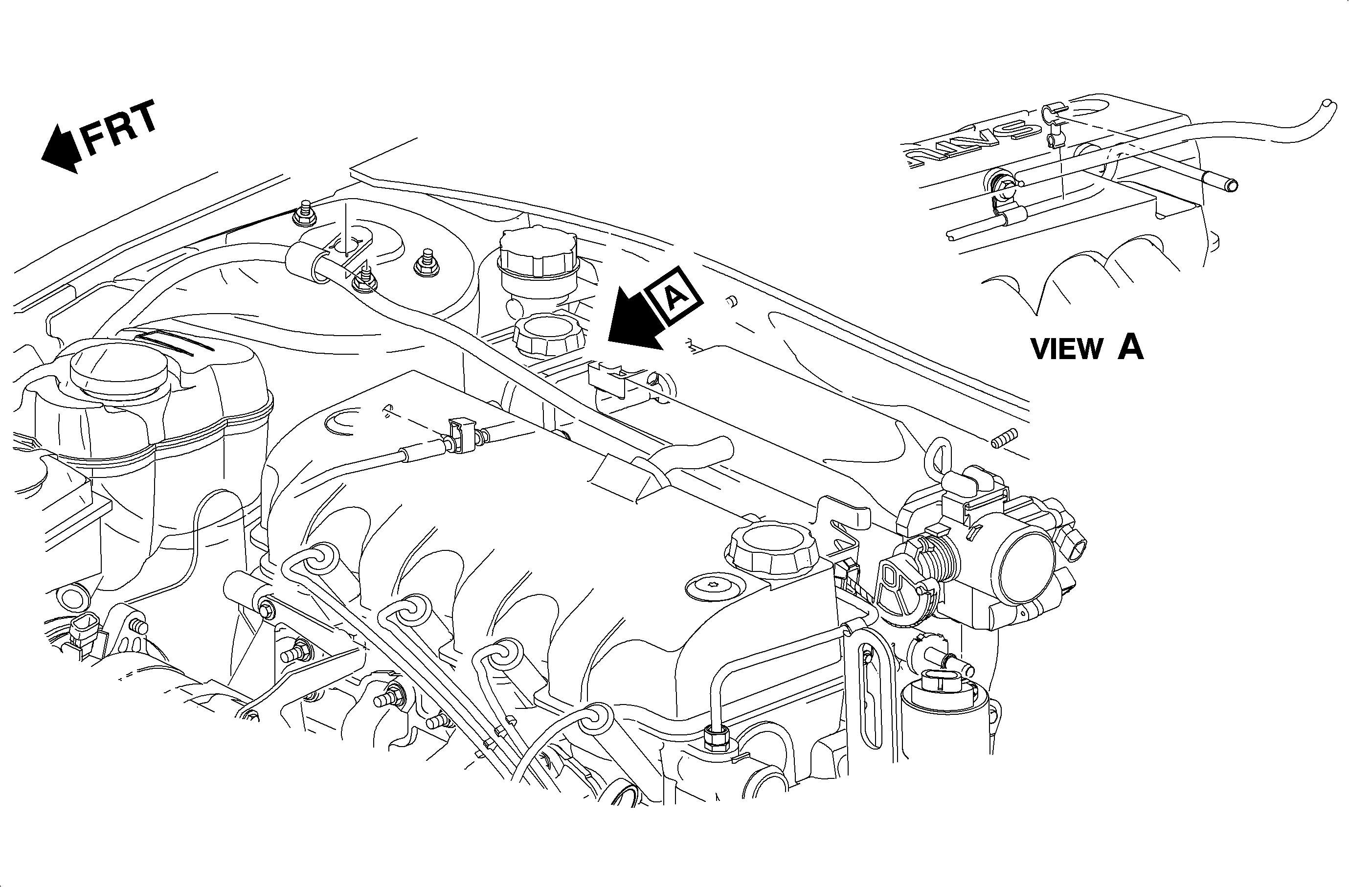
- Remove the positive crankcase ventilation (PCV) valve from the cam cover and rotate it up and away from the throttle cable.
- Release the accelerator control cable from the throttle lever.
- Release the cable retainer locking tangs from the accelerator control cable bracket.
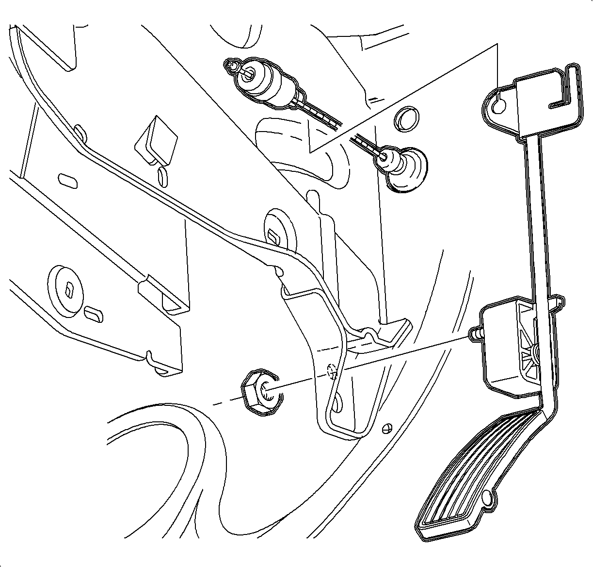
- Release the accelerator control cable from the accelerator pedal assembly.
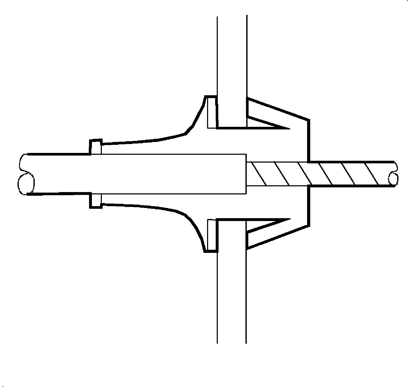
- Release the cable retainer locking tangs from the dash panel (1). Use a wrench to aid in depressing the throttle cable retaining tabs.
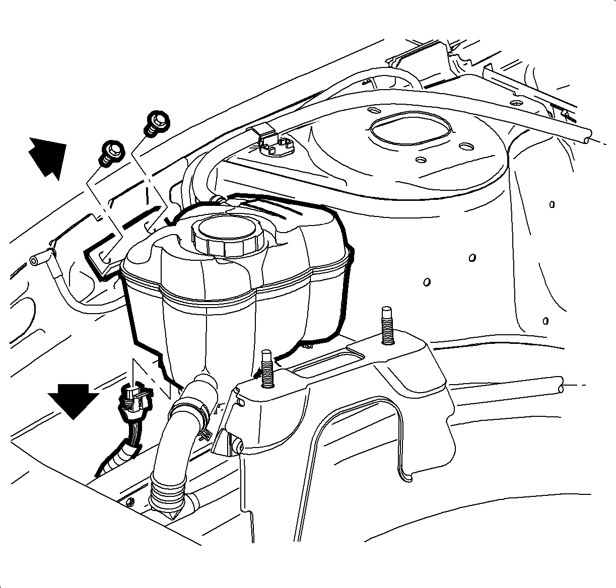
- Remove both coolant surge tank retainer screws.
- Move the windshield washer fluid bottle off to the side.
- Lift the coolant surge tank up and out of its locating holes and disconnect the electrical harness from the low coolant sensor.
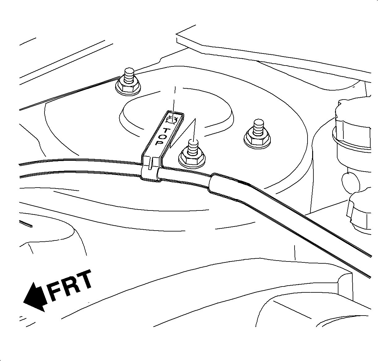
- Remove the accelerator cable retaining clip from the right front suspension strut attachment bolt.
- Remove the retaining clip at the right strut tower. The replacement accelerator cable assembly is supplied with a new retainer clip.
- Remove the cable from the vehicle.
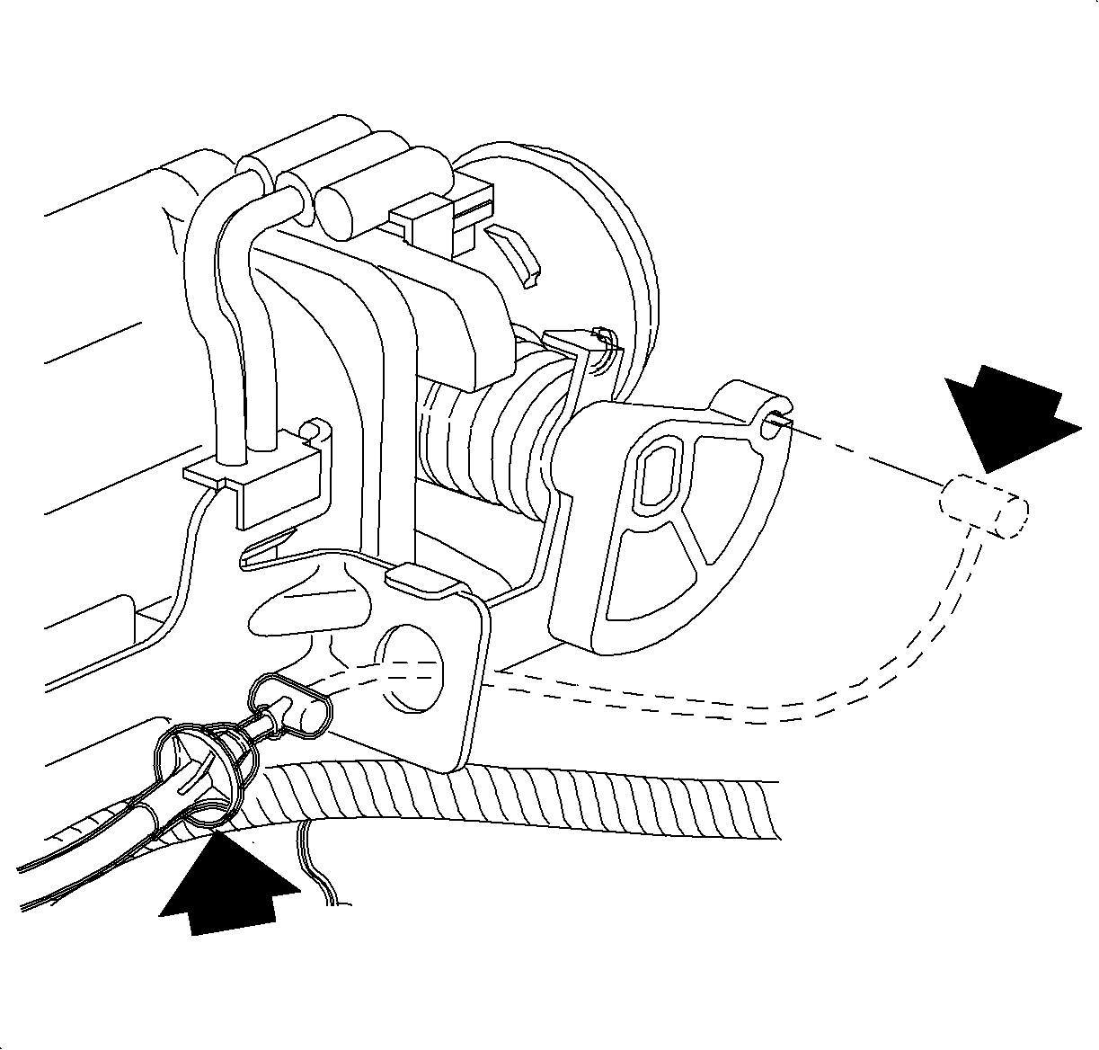
Notice: Accelerator and cruise control cables should not be lubricated. If a binding condition exists with the cable itself, replace the cable assembly.
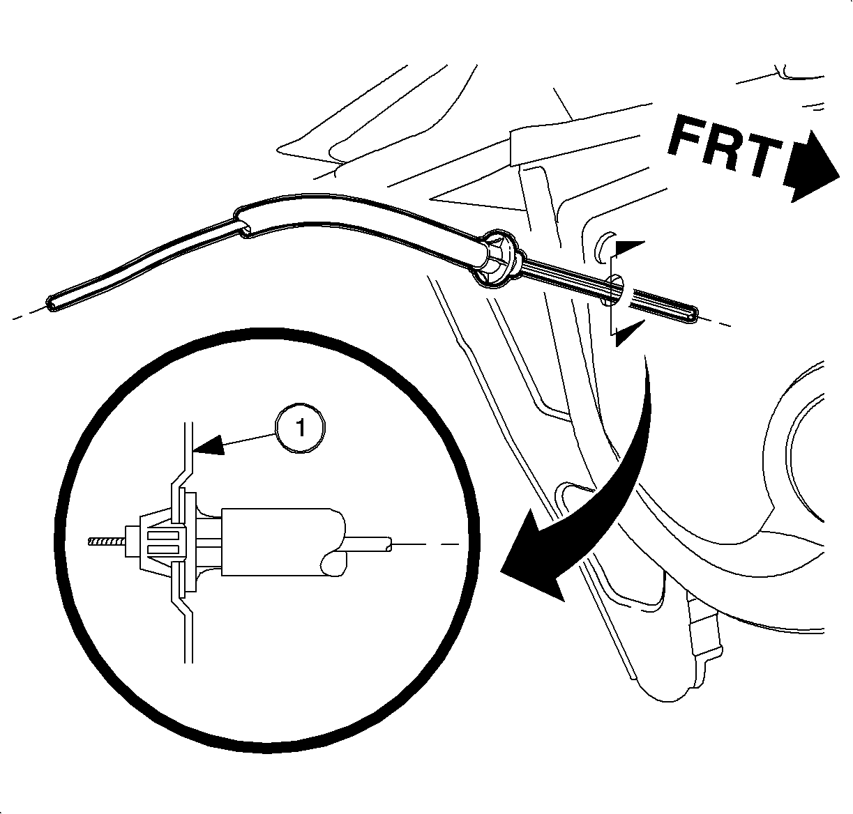
The view illustrates the throttle cable in the installed position.
Installation Procedure
- Route the cable through the front of the dash from the outside in, alongside the right strut tower, under the coolant surge tank, attach the integral retainer clip at the strut attachment bolt, and over to the throttle body bracket.
- Push the cable through the front of the dash to engage the tangs.
- Connect the electrical harness to the low coolant sensor on the coolant surge tank.
- Locate the surge tank to its mount location assuring that the throttle cable is properly routed under and around the tank.
- Install surge tank resonator screws.
- Install the windshield washer bottle and the 2 retaining screws.
- Install the accelerator cable to the throttle body support bracket assuring that the locking tangs engage.
- Install the positive crankcase ventilation (PCV) valve to the cam cover.
- Connect the accelerator cable to the throttle lever.
- Connect the accelerator control cable to the accelerator pedal assembly.
- Check the accelerator control assembly for binding.
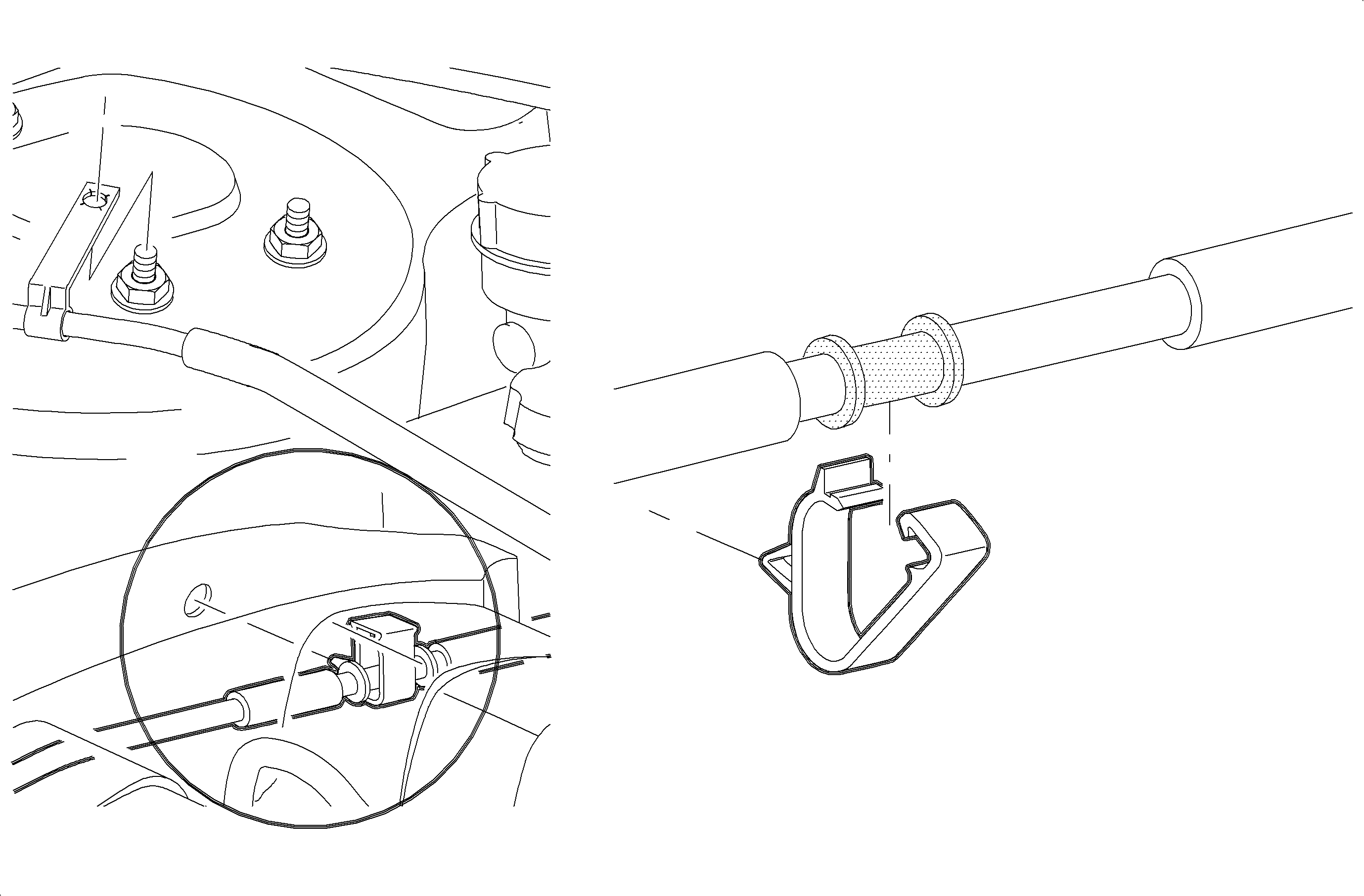
Important: Ensure the cable is located in the lower retaining clip on the strut tower between the locating shoulders on the cable AND the upper retaining clip on the cable is oriented on installation so the TOP, molded on the clip, is visible.
Notice: Whenever a throttle cable assembly is installed, make sure the locking tangs are engaged to the front of dash and the seal is properly installed. The cable should be installed so that the tangs are in a horizontal position to provide optimum sealing. Pull on the cable to ensure the tangs are engaged.
Notice: Refer to Fastener Notice in the Preface section.
Tighten
Tighten the surge tank attachment bolts to 5 N·m (44 lb in).
Tighten
Tighten the washer bottle attachment bolt 4 N·m (36 lb in).


