Removal Procedure
- Raise the vehicle on hoist.
- Remove the rear wheels.
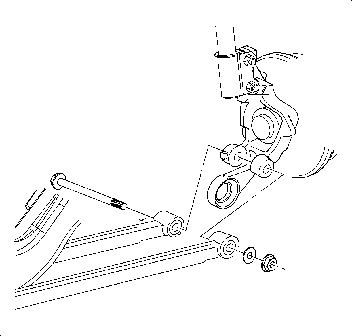
- Remove the left and right trailing arm-to-knuckle nuts.
- Remove the left and right trailing arm-to-body fasteners and remove the arms from the knuckles.
- Remove the lateral link-to-knuckle fasteners on the right and left sides.
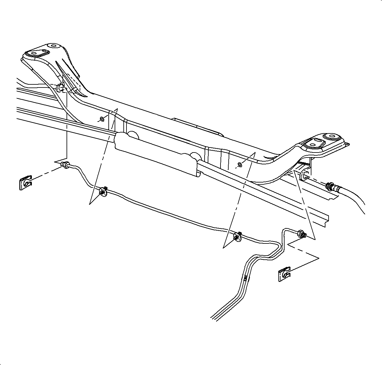
- Unfasten the crossbody brake pipe from the crossmember by unsnapping the brake pipe fasteners from the crossmember.
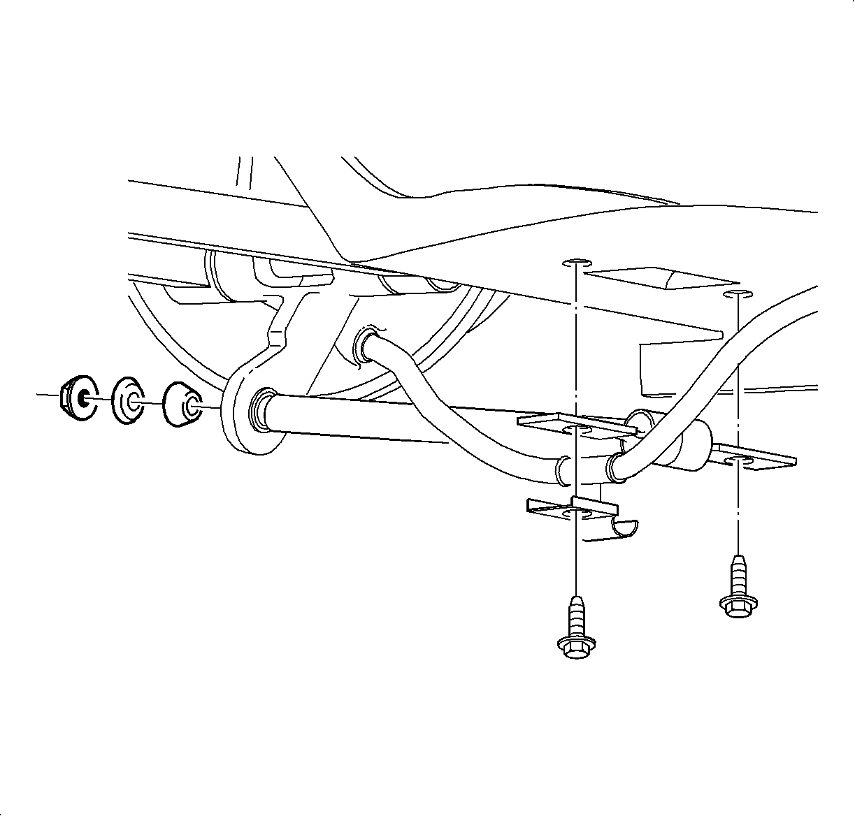
- If equipped with a rear stabilizer shaft, remove the bar-to-link fasteners on the left and right sides.
- Remove the right and left brake pipes from their respective cross member junction brackets.
- Remove the brake hose to cross member securing clips on the right and left sides.
- Remove the brake pipe-to-longitudinal rail fastener.
- Carefully slide the right rear brake pipe out of the crossmember by slowly pulling the pipe from the left side of the crossmember.
- On ABS equipped vehicles, remove the ABS wheel speed sensor harness from the front lateral links and unplug it from the sensors.
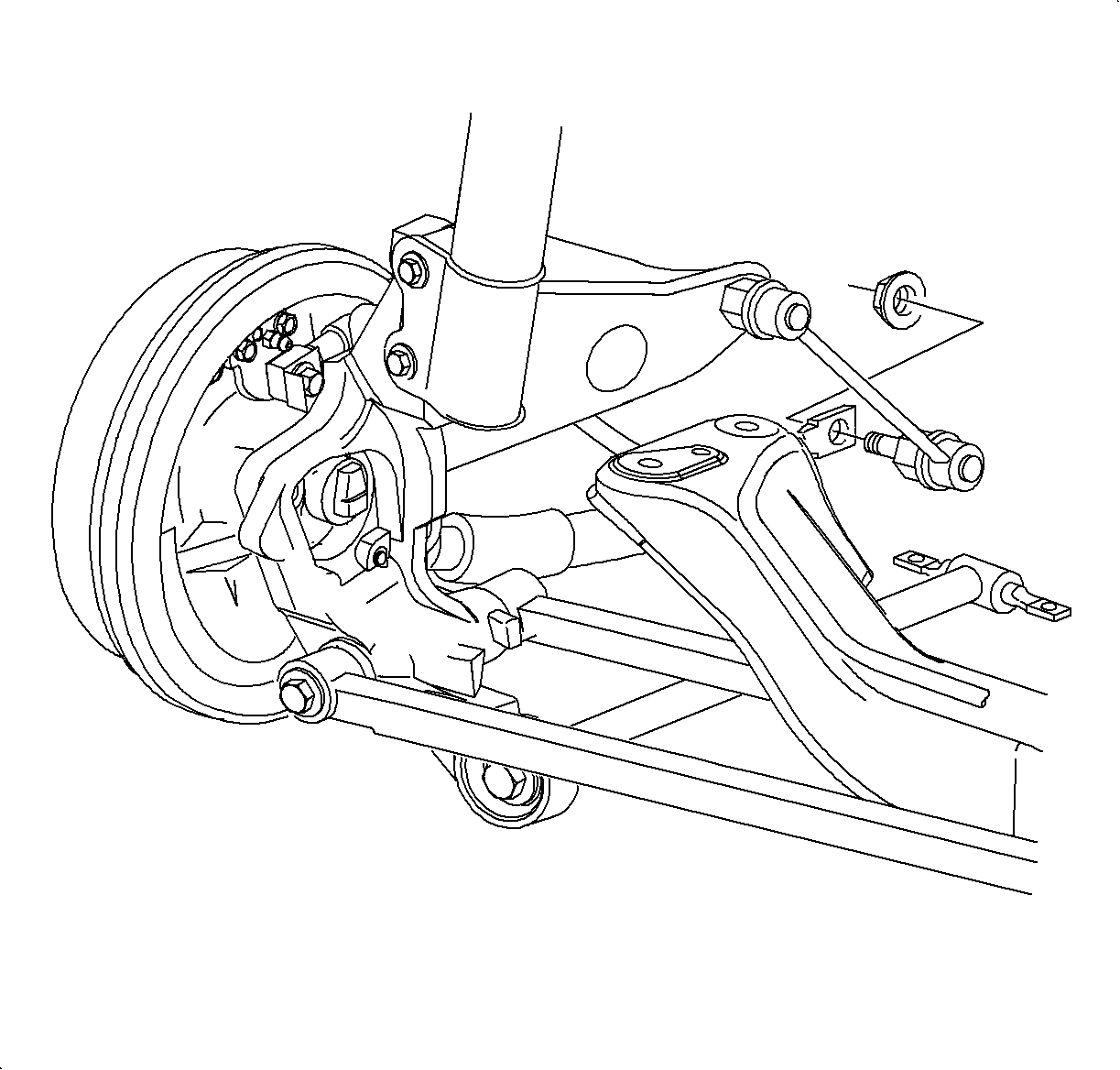
- Support the crossmember with a suitable support stand.
- Remove the 4 crossmember-to-body attachment fasteners.
- Remove the crossmember from the vehicle.
Caution: Ensure that the vehicle is properly supported and squarely positioned. To help avoid personal injury when a vehicle is on a hoist, provide additional support for the vehicle on the opposite end from which the components are being removed.

Important: Note the location and position of the brake pipes prior to loosening and make sure to install the pipes to same position.
Important: Plug the brake pipes to avoid excessive brake fluid loss and contamination.
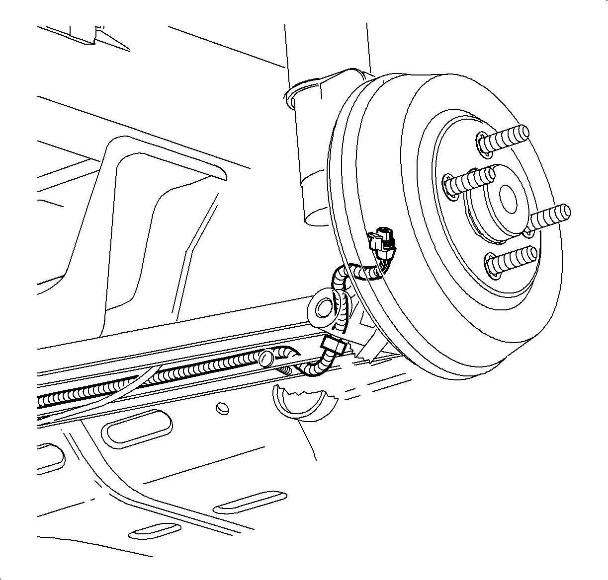
Caution: Failure to support crossmember can cause crossmember to drop to the ground when crossmember mounting bolts are removed.
Caution: Support the front of the vehicle to ensure that the vehicle will not become unbalanced and tip forward, off the hoist, once the rear crossmember is removed (due to decreased proportion of rear vehicle mass). Failure to support front of vehicle could cause vehicle to fall off hoist.
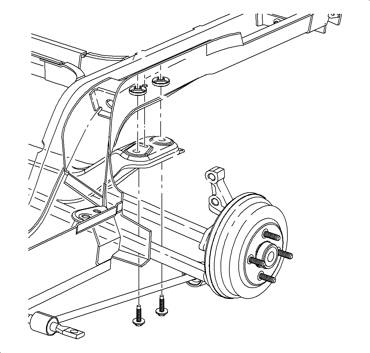
Important: Note the size and location of fasteners. One of the bolts may be slightly larger in diameter than the others. Make sure to use the correct size bolts at the correct locations during installation.
Installation Procedure
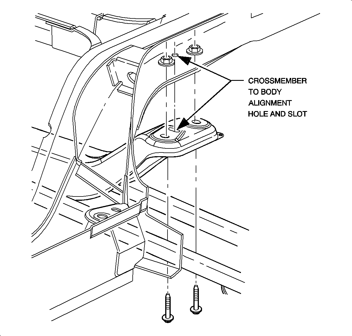
- Install the crossmember onto the vehicle while carefully sliding the rear brake line into the crossmember. Align the crossmember to the body using a 3/8 in rod at the alignment hole and slot.
- Install the fasteners and torque to specification.
- Place the trailing arm, with bushings, into the knuckle and install the fastener nut.
- Install the trailing arm into the body and secure it with fasteners.
- Install the lateral links onto the knuckle and install the fasteners.
- Torque the trailing arm-to-knuckle nut.
- Torque the lateral link-to-knuckle fasteners.
- If equipped with a rear stabilizer shaft, install the rear stabilizer shaft onto the links with a fastener and torque to specification.
- Attach the left and right brake hoses to the crossmember with the securing clips.
- Install the right and left brake pipes into their respective crossmember junction brackets.
- Install the brake pipe to the longitudinal rail fastener.
- On ABS equipped vehicles, install the ABS wheel speed sensor harness to the front lateral link and plug it into sensor.
- Bleed the brakes. Refer to the appropriate brake bleeding procedure in the Brakes Service Manual.
- Position the wheel onto the hub.
- Install the wheel nuts and tighten the wheel nuts in a crisscross pattern. Repeat the tightening pattern to ensure the torque is correct.
- Lower the vehicle from the hoist.
- Perform the vehicle wheel alignment. Refer to Wheel Alignment Specifications in Wheel Alignment.
Notice: Refer to Fastener Notice in the Preface section.
Important: New bolts of the correct size and at the correct location must be used.
Tighten
Tighten the crossmember-to-body fastener to 120 N·m (89 lb ft).
Important: Do not torque the fastener at this time.
Tighten
Tighten the trailing arm-to-body fasteners to 120 N·m (89 lb ft).
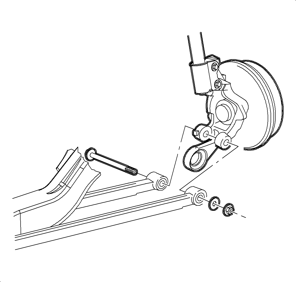
Important: Do not torque the fasteners at this time.
Tighten
Tighten the trailing arm-to-knuckle fasteners to 100 N·m (74 lb ft).
Tighten
Tighten the lateral link-to-knuckle fastener to 165 N·m (122 lb ft).

Tighten
Tighten the rear stabilizer shaft-to-link fastener to 40 N·m (30 lb ft).


Notice: Before installing wheels, remove rust or corrosion from wheel mounting surfaces and brake rotors/drums. Failure to do so can cause wheel nuts to loosen in service.
Tighten
Tighten the wheel nuts to 140 N·m (103 lb ft).
