For 1990-2009 cars only
Removal Procedure
- Disconnect the negative battery cable.
- Remove the brake fluid level switch electrical connector from the master cylinder reservoir.
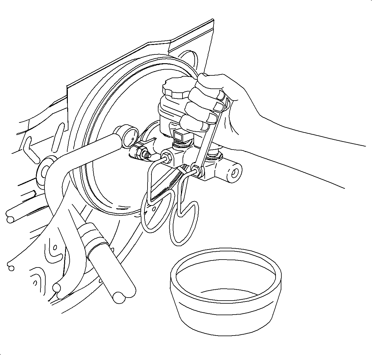
- Remove the brake pipe nuts from the master cylinder, not the ABS assembly
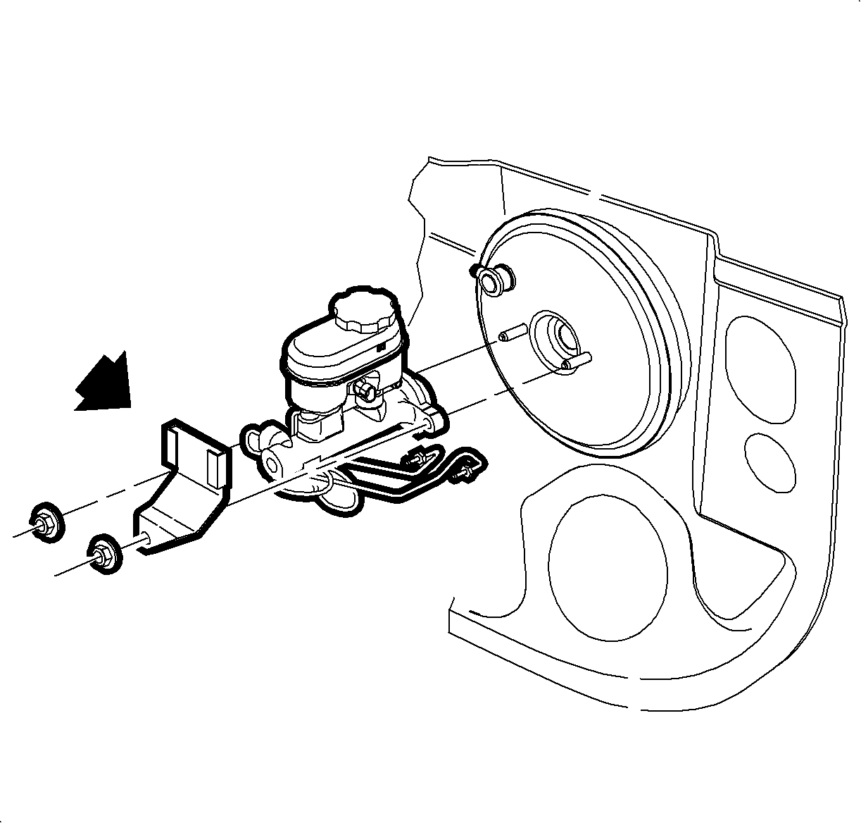
- Remove the two master cylinder-to-brake booster attachment nuts.
- Remove the master cylinder.
Caution: Refer to Battery Disconnect Caution in the Preface section.

Notice: After removing brake pipe nuts, do not excessively pull or bend brake pipes away from master cylinder.
Notice: Plug open brake pipes to prevent brake fluid loss and contamination.

Important: On manual transaxle vehicles, the clutch reservoir and the bracket will need to be removed and put aside.
Installation Procedure
- Position the master cylinder onto the brake booster studs and install the fastening nuts.
- Position brake pipes into the master cylinder and tighten the brake pipe nuts.
- Connect the electrical connector for the brake fluid level switch.
- Connect the negative battery cable.
- Fill the brake fluid reservoir with clean brake fluid up to the base of the reservoir fill neck.
- Bleed the brake system. Refer to Antilock Brake System Automated Bleed Procedure .
- Check the brake fluid level.
- Check for leaks with the engine running and the brakes applied.
Notice: Refer to Fastener Notice in the Preface section.

Important: On manual transaxle equipped vehicles, install the clutch reservoir bracket prior to installing fasteners.
Tighten
Tighten the nut to 27 N·m (20 lb ft).
Tighten
Tighten the nuts to 32 N·m (24 lb ft).
Tighten
Tighten the nut to 17 N·m (13 lb ft).
