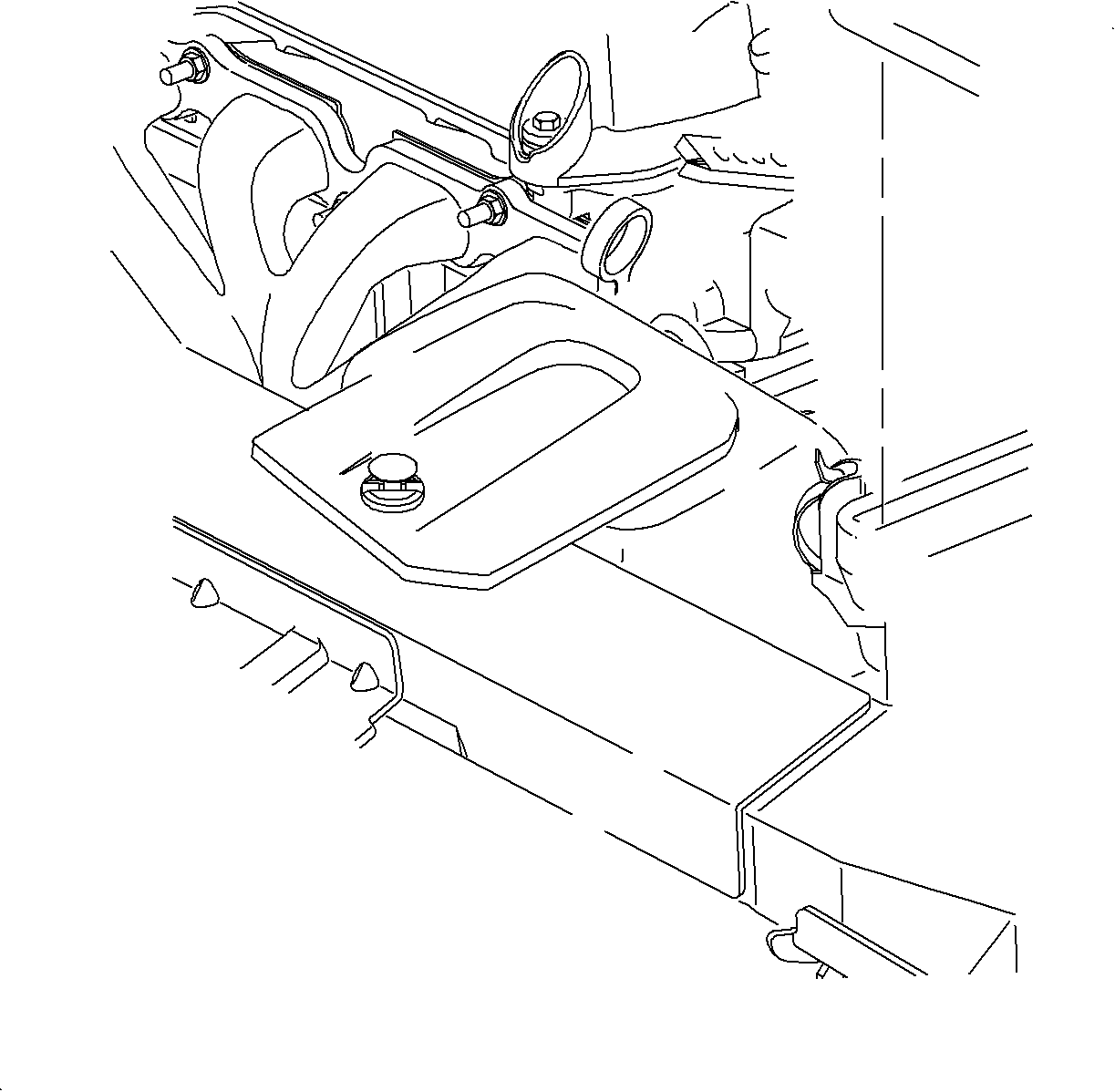
For 1990-2009 cars only
Removal Procedure
Important: For gasket damages of 5/8 in or larger, the EBTCM unit should be replaced. You will need to obtain Loctite 5900® to repair the damaged gasket.
- Clean the control module surface area.
- Locate the damage(s) on the gasket.
- Clean and dry the damaged area(s). Remove pieces of the damaged gasket.
- Cut the tip of the nozzle to desired opening. Gaskets are best formed using a 1/16 in. or 1/8 in. bead.
- Carefully apply Loctite 5900® gasket material evenly to damage area. Do not leave any gaps between the gasket groove, original seal, and new material.
- Fill the gaps by smoothing out the seal using a piece of plastic (or equivalent).
- Once the gasket has been repaired, join the housing together and install the screws. Remove excess material immediately.
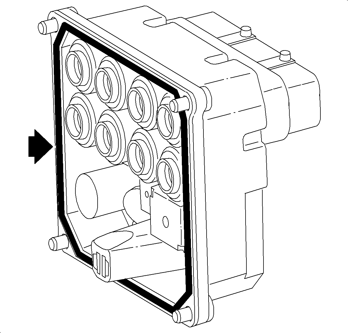
Tighten
Tighten the control module-to-valve assembly screws to 4-6 N·m
(35-53 lb in).
Installation Procedure
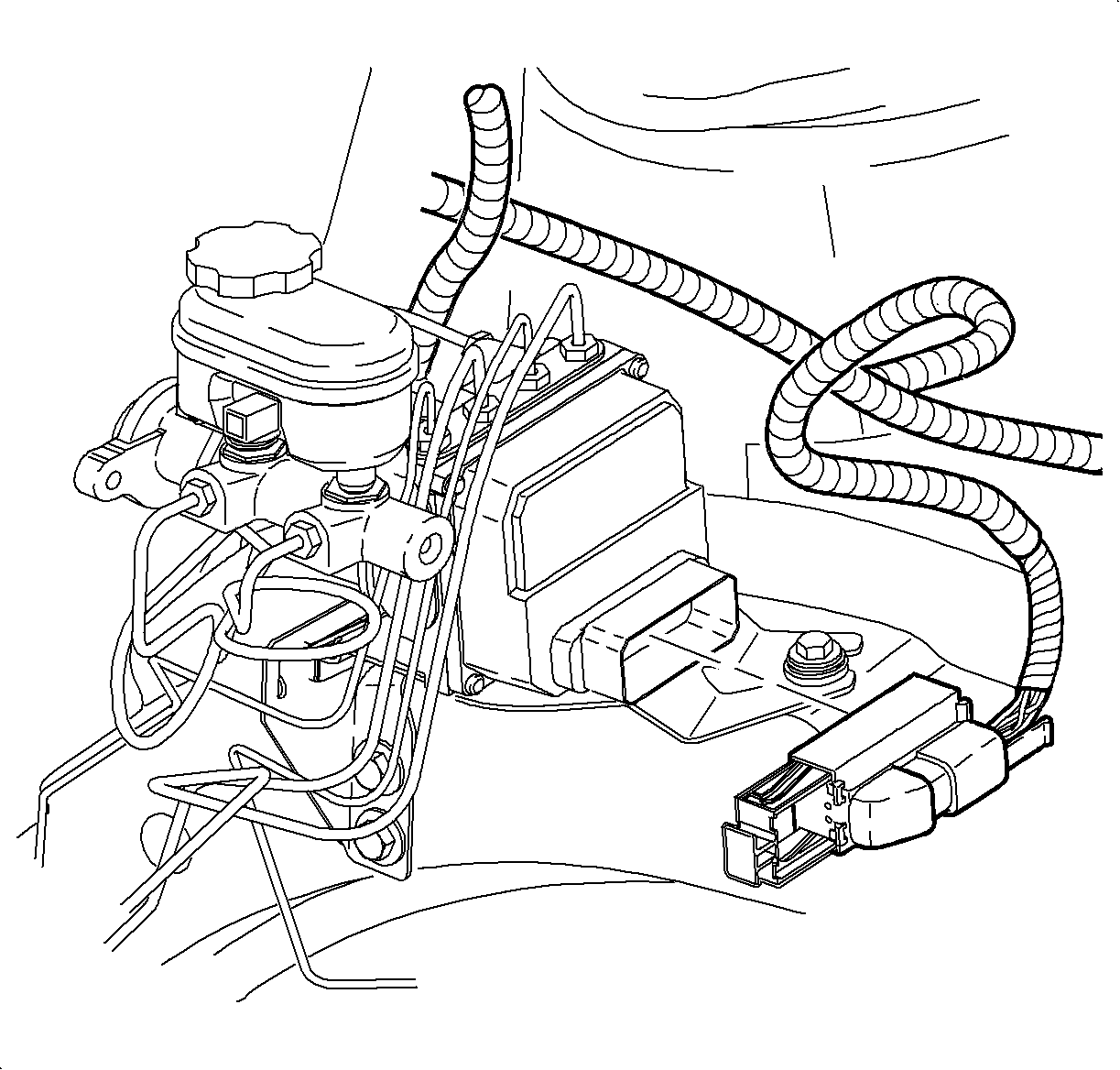
- Position ABS control assembly on the mid-rail bracket by sliding towards the rear of the vehicle. Slide rearward to align the bracket tab into the bracket slot, then install and torque the mid-rail bolt.
- Remove plugs from the brake pipes and install the brake pipes to the proper location on the valve assembly.
- Install the control module electrical connector.
- Connect the electrical connector and push in the tab to lock.
- Connect the brake fluid level switch electrical connector.
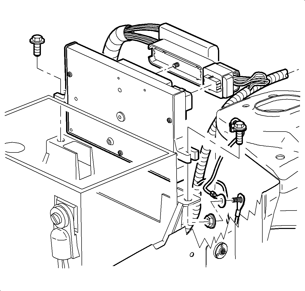
- Place the powertrain control module (PCM) in carrier.
- Connect the body electrical connector.
- Install and torque the PCM attachment bolts.
- Install the air induction cover and the hose assembly.
- Fill the brake fluid reservoir to the base of the reservoir filler neck with DOT 3 brake fluid.
- Bleed the brake system using a scan tool. Refer to Antilock Brake System Automated Bleed Procedure .
Notice: Refer to Fastener Notice in the Preface section.
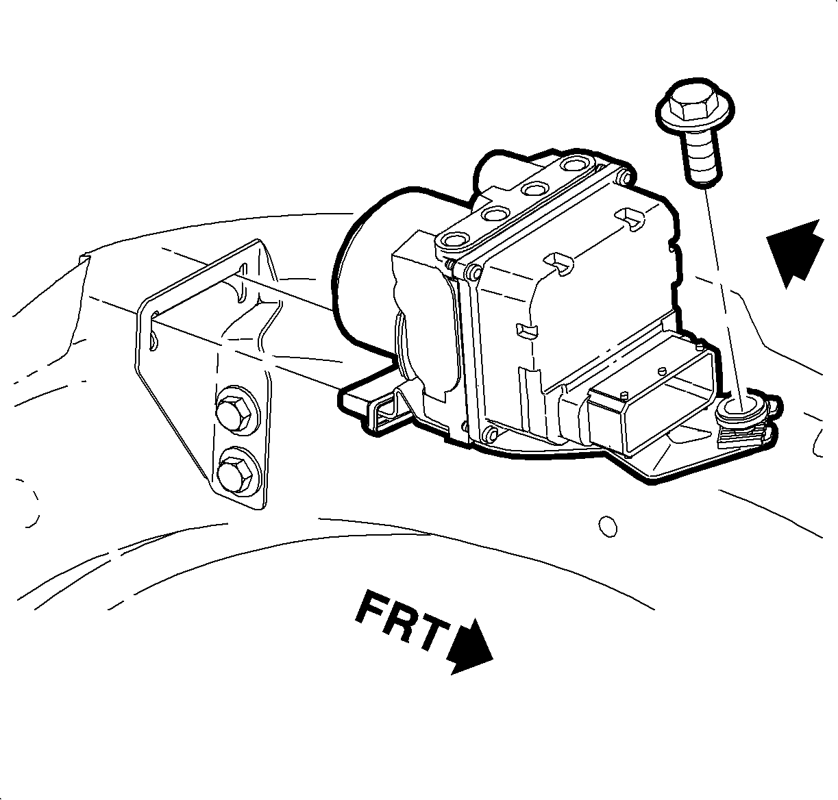
Tighten
Tighten the ABS control assembly-to-mid-rail bracket bolt to 12 N·m
(9 lb ft).
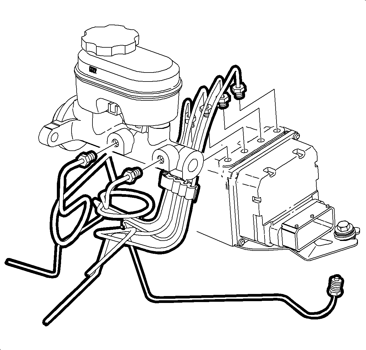
Tighten
Tighten the brake pipe-to-ABS assembly to 32 N·m (24 lb ft).
Tighten
Tighten the PCM attachment bolts to 6 N·m (53 lb in).
