Tools Required
| • | SA9201BR Drum Brake Adjusting |
| • | SA92109NE Calipers |
Disassembly Procedure
Left side shown; right side opposite.
- Release the park brake.
- Raise the vehicle on a hoist.
- Remove the rear wheel and tire assembly.
- Remove the brake drum.
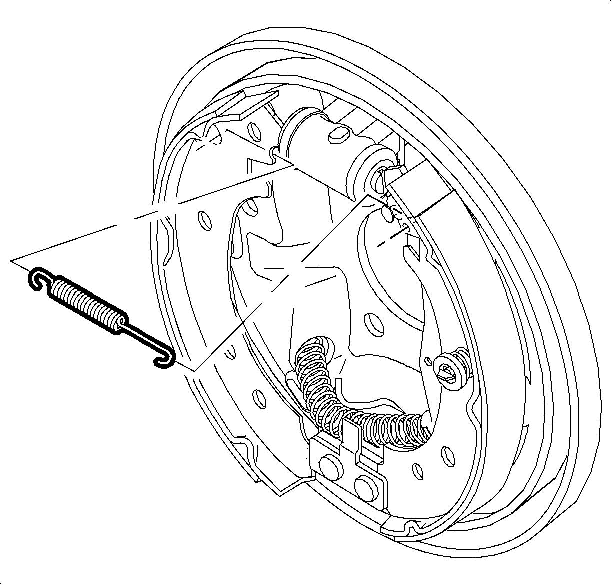
- Remove the lower return spring.
- Remove the adjuster spring.
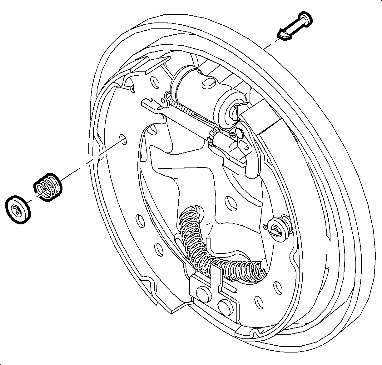
- Remove the leading shoe hold down cup, spring, and pin.
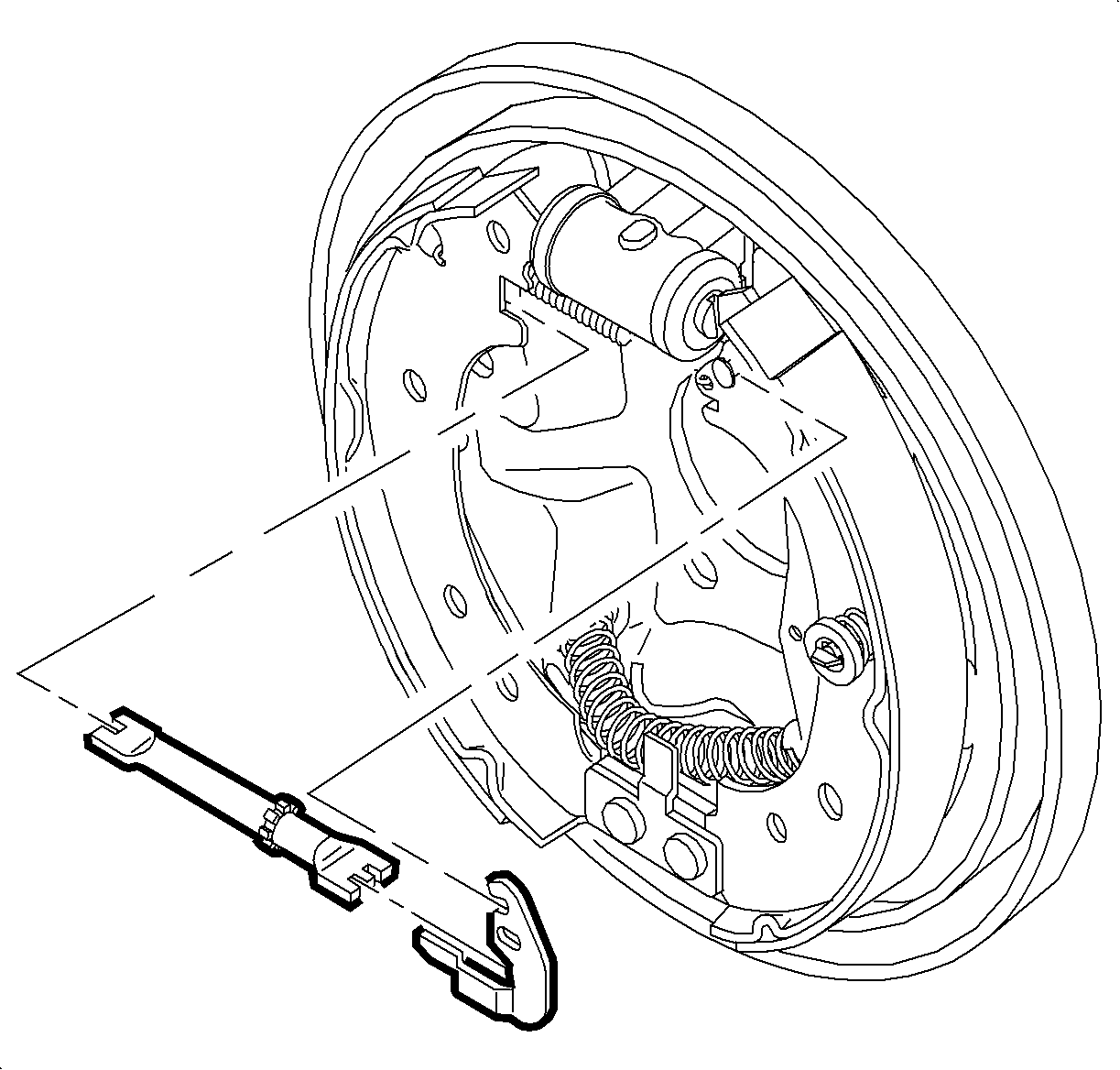
- Remove the adjuster assembly and the adjuster lever. If difficulty is encountered, proceed as follows:
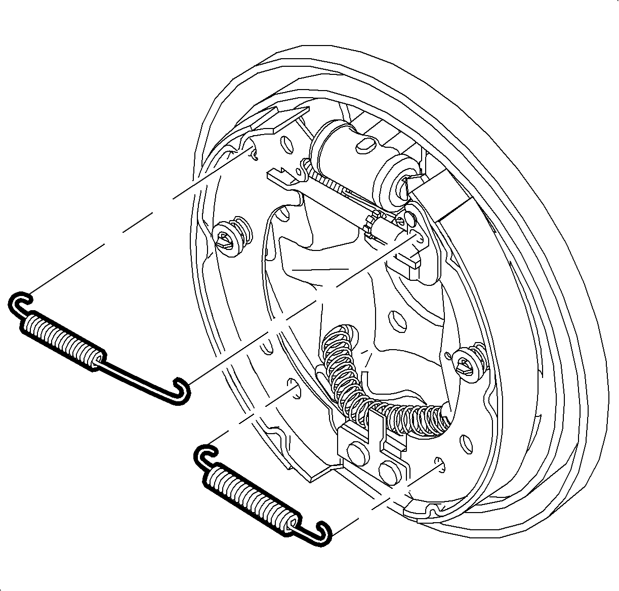
- Remove the leading shoe by twisting the shoe out of engagement with the upper return spring.
- Remove the upper return spring from the park brake shoe.
- Remove the park brake shoe hold down cup, hold down spring, and hold down pin.
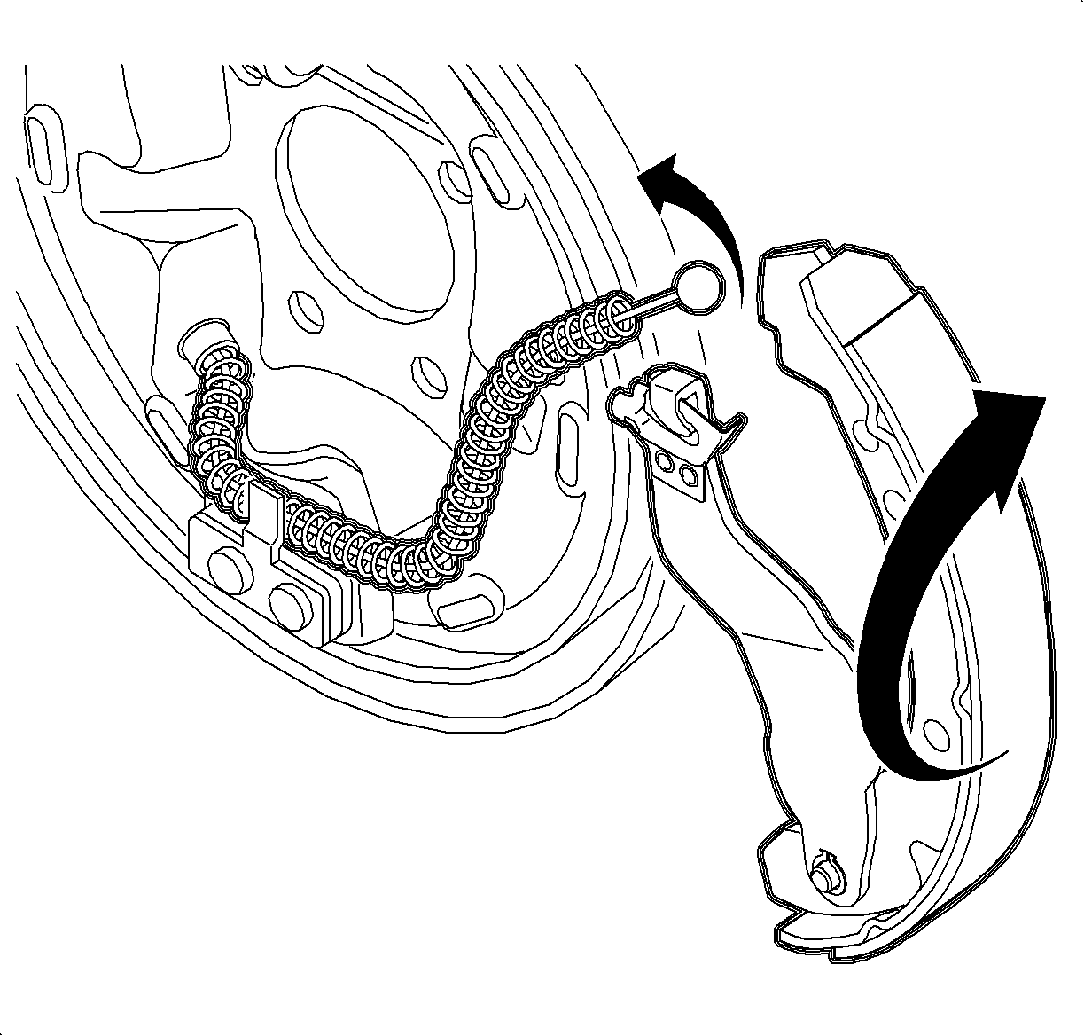
- Remove the park brake cable from the park brake lever by pushing the lever into the cable spring, while at the same time disengaging the cable end from the lever.
- Remove the park brake shoe, along with the park brake lever and cable spring.
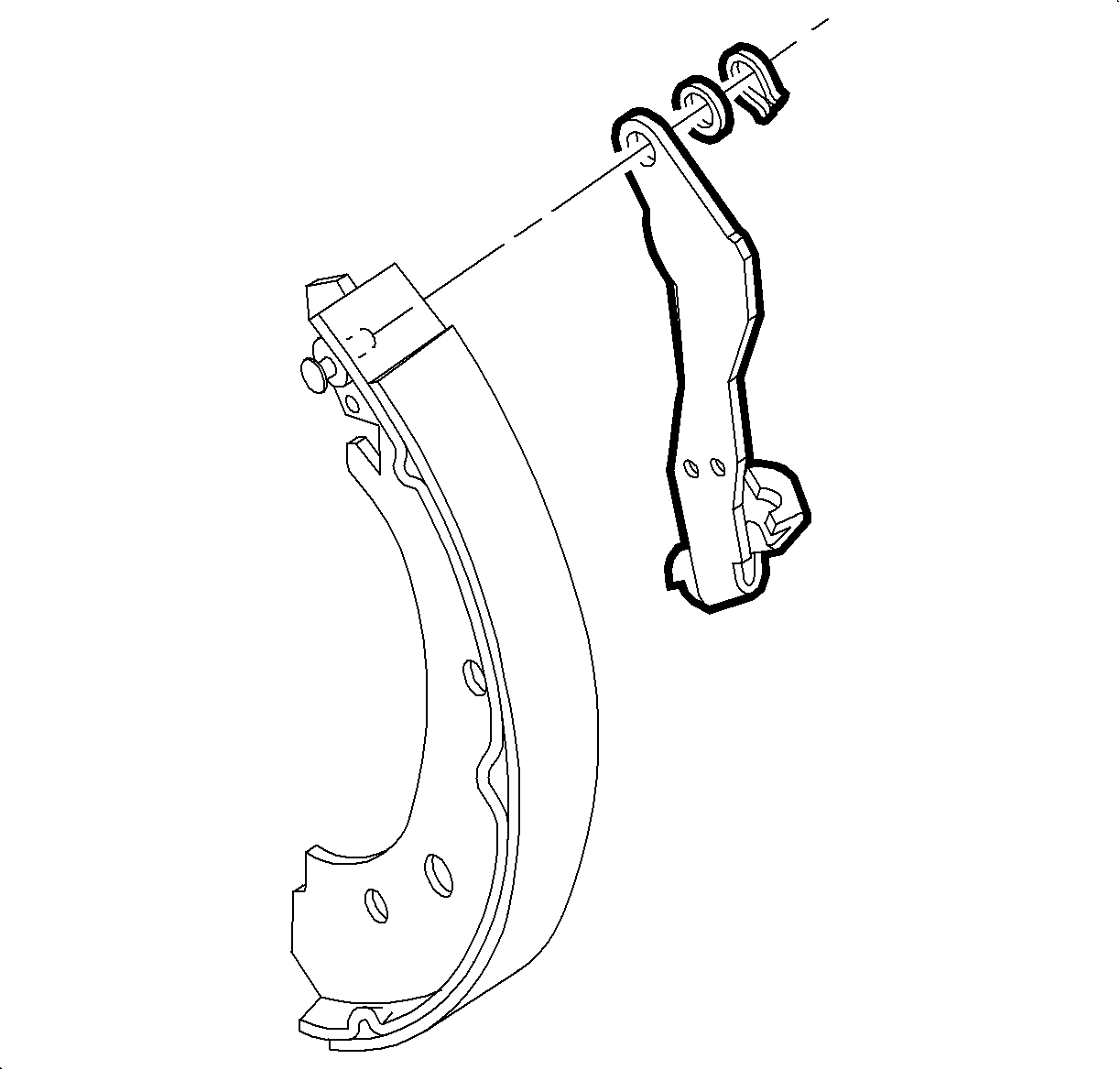
- Remove the park brake lever retainer and the wave washer, and separate the lever from the park brake shoe.
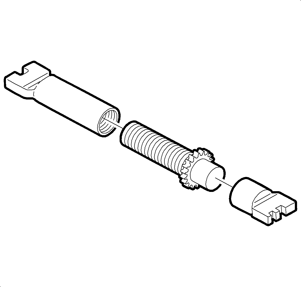
- Disassemble the brake adjuster components adjusting the socket, screw, and nut.
- Clean the adjusting socket, screw, and nut in clean, denatured alcohol.
- Inspect the adjuster assembly, making sure that the adjuster screw threads smoothly into the adjusting nut, over the full threaded length.
- Inspect the wheel cylinder for leakage or damaged boots. Also, make sure that the wheel cylinder is not seized.
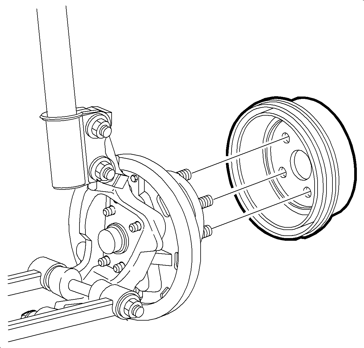
Caution: Ensure that the vehicle is properly supported and squarely positioned. To help avoid personal injury when a vehicle is on a hoist, provide additional support for the vehicle on the opposite end from which the components are being removed.
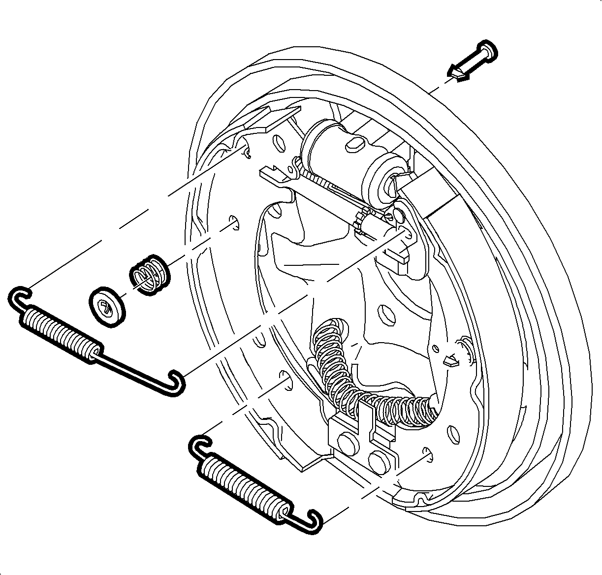
Notice: Do not pry against brake backing plate. This will bend plate.
Important: If difficulty is encountered removing the drum, use SA9201BR (or equivalent) to turn star wheel adjuster assembly to shorten its length to provide sufficient drum-to-shoe clearance for drum removal.
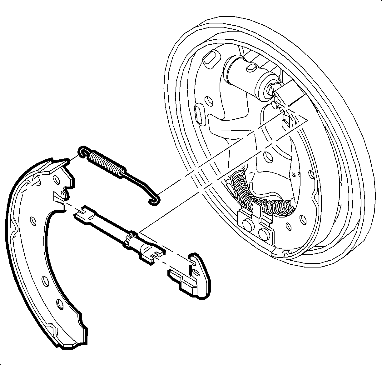
| 8.1. | Pull the leading shoe towards the front of the vehicle, freeing the adjuster assembly. Remove the assembly. |
| 8.2. | If necessary, turn star wheel on adjuster to shorten its length. |
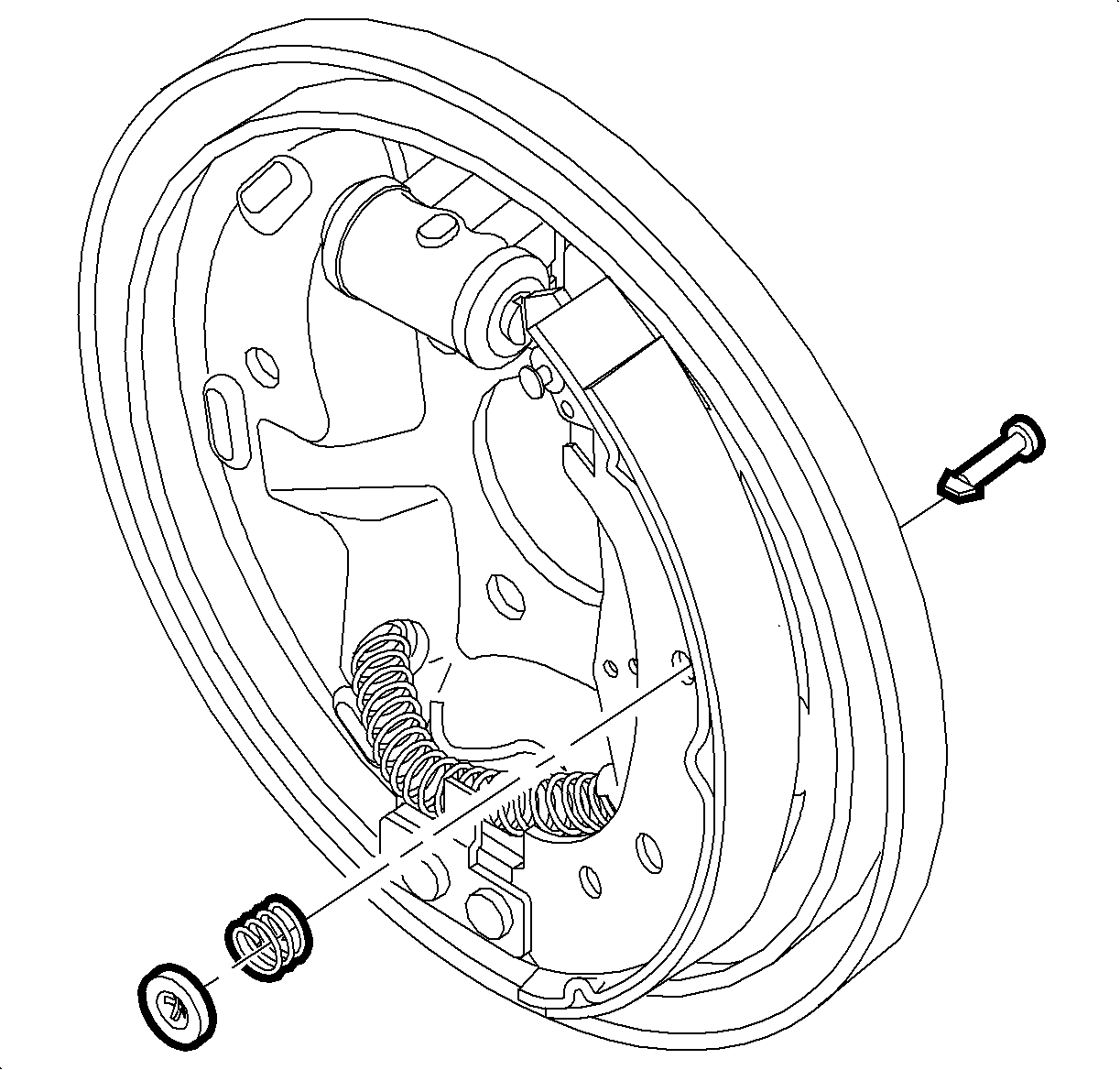
Important: If the wheel cylinder is found to be damaged, replace it. Do not attempt to repair the wheel cylinder.
Assembly Procedure
Important: When replacing the rear brake shoes, inspect the backing plate for excessive wear at the six raised shoe contact pads. Excessive wear at the raised shoe contact pads, such as notches or deep grooves, could restrict shoe travel.
Important: Never replace brake shoes/linings on one side of axle only. Brake shoes/linings must be replaced as axle sets.
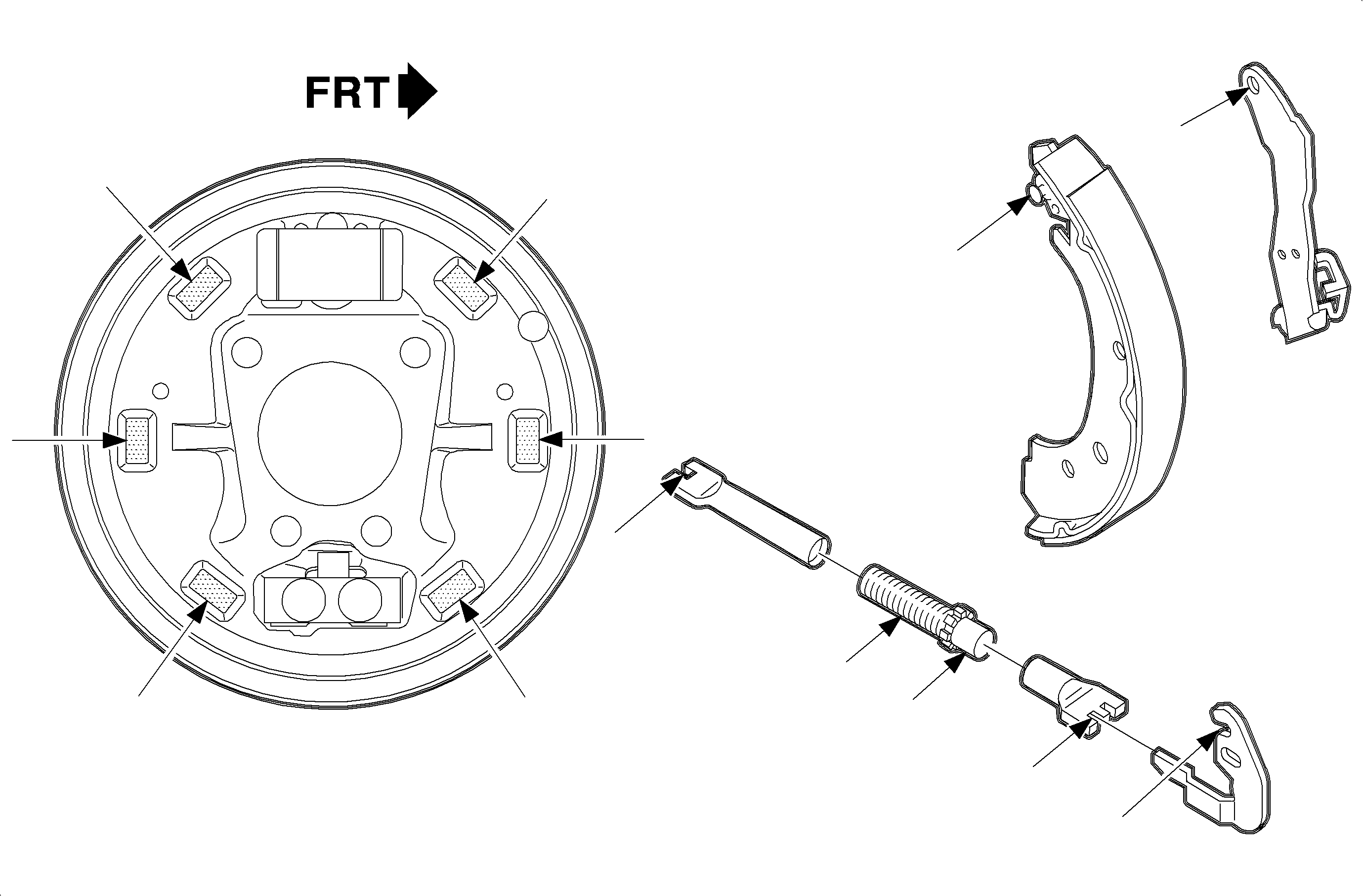
- Lubricate the following components:
- Install the park brake lever assembly onto the pin on the park brake shoe and secure with the wave washer and retainer clip.
- Install the cable spring into the cage on the park brake lever only if the cable spring was removed.
- Install the park brake cable, through the cable spring, onto the park brake lever.
- Install the park brake shoe by positioning the shoe and installing the hold down pin, hold down spring, and hold down cup.
- Install the long, straight end of the upper return spring into the back of the hole in the park brake shoe.
- Install the other end of the upper return spring into the back of the leading brake shoe. Stretch the spring to correctly position the leading shoe on the backing plate.
- Pull the leading shoe toward the front of the vehicle and install the adjuster assembly between the park and leading brake shoes.
- Install the adjuster lever.
- Install the leading brake shoe by positioning the shoe and installing the hold down pin, hold down spring, and hold down cup.
- Install the adjuster spring by placing the short end of the adjuster spring into the hole in the leading shoe and stretching the other end of the spring into the hole in the adjuster lever.
- Install the lower return spring by hooking one end of the spring into the hole of one shoe and stretching other end of the spring into the hole of the other shoe.
- Check the assembly for the correct location and installation of the springs and components.
- Using a 0-200 mm (0-8 in) caliper such as SA92109NE (or equivalent), measure the inside diameter of the brake drum.
- Measure the outside diameter of the brake shoes and the adjust brake adjuster to obtain 0.50 mm (0.020 in) less than the reading obtained in step 14.
- Install the brake drum.
- Bleed the brakes if new a wheel cylinder or backing plate has been installed.
- Position the wheel and tire assembly onto the hub.
- Install the wheel nuts and tighten in a crisscross pattern. Repeat the tightening pattern to be sure the torque is correct.
- Lower the vehicle from the hoist.
- Apply and release the brake pedal 20 times to allow the adjuster to position the brake shoes.
- Adjust the park brake. Refer to Park Brake Adjustment in Park Brake.
| 1.1. | The adjuster assembly -- Apply to the threads of the screw and the inner diameter face of the socket. |
| 1.2. | The adjuster lever surfaces that rub on the brake shoe web |
| 1.3. | The backing plate at the six raised shoe contact pads |
| 1.4. | The park brake lever pin and the surfaces that contact the brake shoe web |

Important: Make sure to crimp the ends of the retainer securely to retain park brake lever.


Notice: Check that the brake shoe is correctly engaged in the wheel cylinder on top and anchor on bottom.
Notice: Check that the brake shoe is correctly engaged in the wheel cylinder on top and anchor on bottom.
Notice: Check that notch on adjuster lever engages pin on park brake shoe and notch on adjusting socket.
Notice: Check that lower leg of adjusting lever engages teeth of star wheel on adjuster assembly.
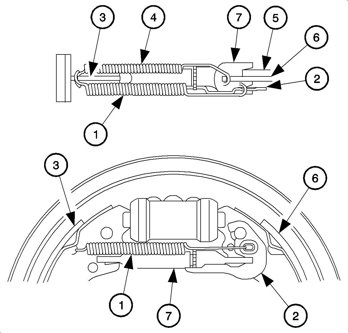
| • | Adjuster Spring (1) |
| • | Adjuster Lever (2) |
| • | Leading Shoe (3) |
| • | Upper Return Spring (4) |
| • | Park Brake Lever (5) |
| • | Park Brake (6) |
| • | Adjuster Assembly (7) |
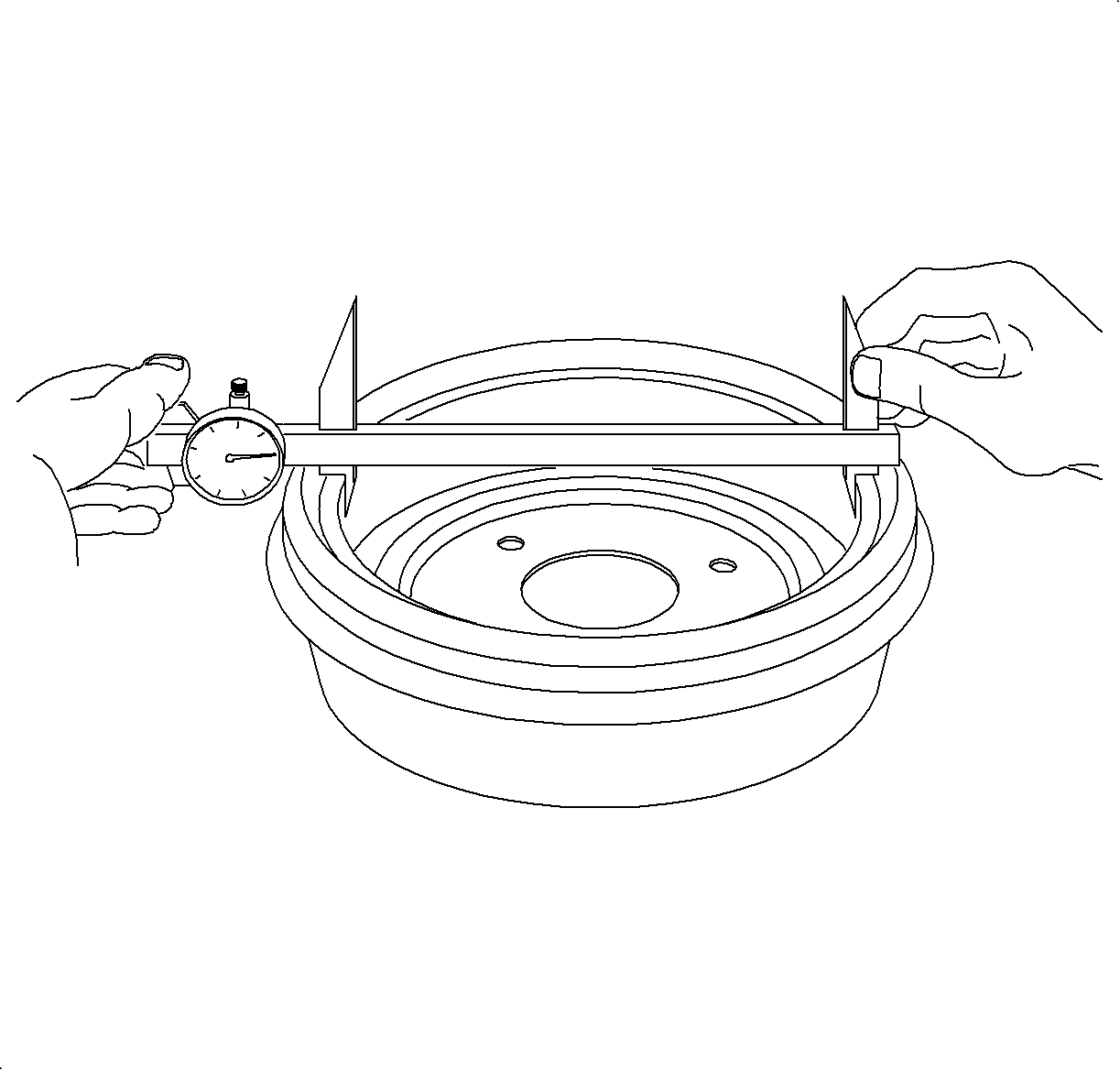
Rear Drum Diameter
New: 200.0 mm (7.87 in)
Maximum after Turning: 200.6 mm (7.90 in)
Discard: 201.4 mm (7.93 in)
Refer to Brake Drum Surface and Wear Inspection .
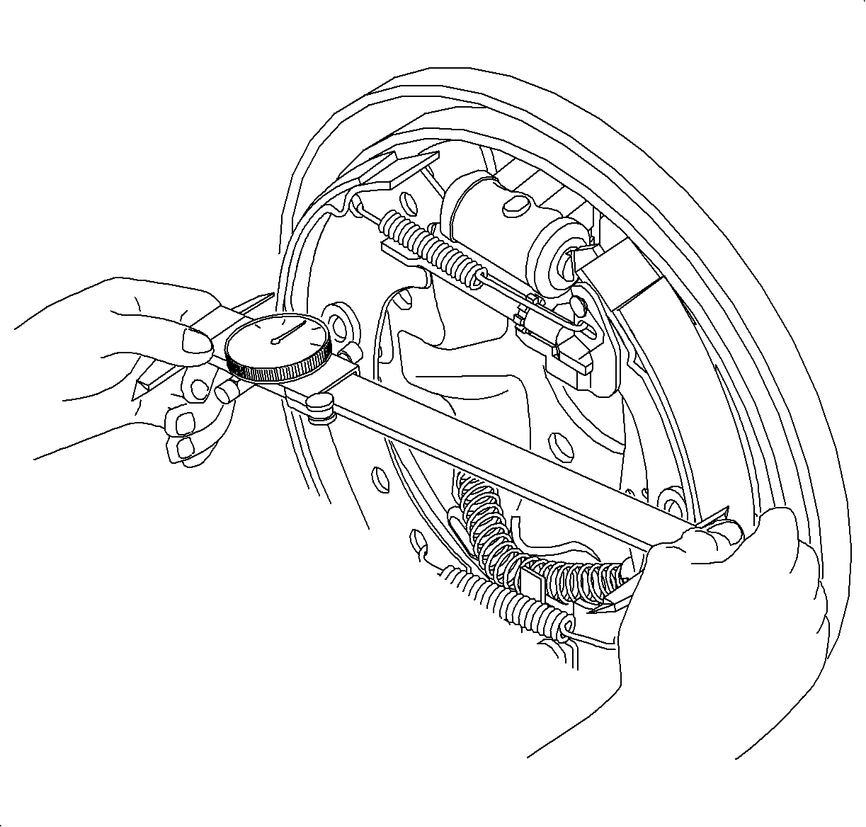
Notice: Before installing wheels, remove rust or corrosion from wheel mounting surfaces and brake rotors/drums. Failure to do so can cause wheel nuts to loosen in service.
Notice: Refer to Fastener Notice in the Preface section.
Tighten
Tighten the wheel nut to 140 N·m (103 lb ft).
