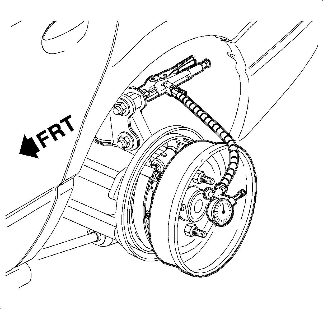
For 1990-2009 cars only
On-Vehicle
- Remove the road wheel.
- Remove the brake drum and install it on the hub backwards. Secure the drum with two wheel nuts also installed backwards, with the flat side toward the drum.
- Fasten a dial indicator to the knuckle or strut-to-knuckle fastener.
- Position the dial indicator tip against the brake drum shoe surface.
- Rotate the drum to the lowest reading.
- Zero the dial indicator.
- Rotate the drum one complete revolution and observe total indicated runout (TIR).
- Move the dial indicator neck to allow the removal of the brake drum. It is not necessary to remove the dial indicator from the knuckle or strut-to-knuckle fastener.
- Remove the brake drum from the hub and turn 180 degrees and again, install it on the hub backward. Secure the brake drum with two wheel nuts also installed backwards, with the flat side towardthe brake drum.
- Position the dial indicator tip against the brake drum shoe surface.
- Rotate the brake drum to the lowest reading.
- Zero the dial indicator.
- Rotate the brake drum one complete revolution and observe total indicated runout (TIR).
- Remove the brake drum and it install on a brake lathe.
- Fasten a dial indicator to the lathe.
- Position the dial indicator tip against the brake drum shoe surface.
- Rotate the brake drum to the lowest reading.
- Zero the dial indicator.
- Rotate the brake drum one complete revolution and observe total indicated runout.
- If brake drum radial runout exceeds 0.15 mm (0.006 in), refinish brake drum as long as refinishing does not exceed brake drum maximum diameter of 200.6 mm (7.90 in) after turning. If brake drum exceeds maximum diameter, replace the brake drum.
- Subtract total indicated runout (TIR) measurement obtained in step 19 (brake drum runout) from TIR measurement obtained in step 7 (combined brake drum and hub runout). The difference between these two readings represents hub runout.

| 7.1. | If combined brake drum and hub radial runout does not exceed 0.28 mm (0.011 in), proceed to step 8. |
| 7.2. | If combined drum and hub radial runout exceeds 0.28 mm (0.011 in), proceed to step 14. |
Specification
Maximum TIR (combined brake drum and hub) 0.28 mm (0.011 in)
Specification
Maximum TIR (combined brake drum and hub) 0.28 mm (0.011 in)
| 13.1. | If combined brake drum and hub radial runout does not exceed 0.28 mm (0.011 in), brake drum and hub are within specification and no repair is required. Refer to brake pulsation diagnosis in the appropriate year service manual. |
| 13.2. | If combined brake drum and hub radial runout exceeds 0.28 mm (0.011 in), proceed to step 14. |
Specification
Maximum TIR (brake drum) 0.15 mm (0.006 in)
Combined Drum and Hub Runout -- Drum Runout = Total Hub Runout
If hub runout exceeds 0.13 mm (0.005 in), replace the hub and bearing assembly.
Off-Vehicle
- Remove the road wheel.
- Remove the brake drum and it install on a brake lathe.
- Fasten a dial indicator to the lathe.
- Position the dial indicator tip against the drum surface.
- Rotate the drum to the lowest reading.
- Zero the dial indicator.
- Rotate the brake drum one complete revolution and observe total indicated runout (TIR).
Specification
Maximum Radial Runout (Drum) 0.15 mm (0.006 in)
