Removal Procedure
- Raise the vehicle on a hoist.
- Remove the wheel and disc assembly.
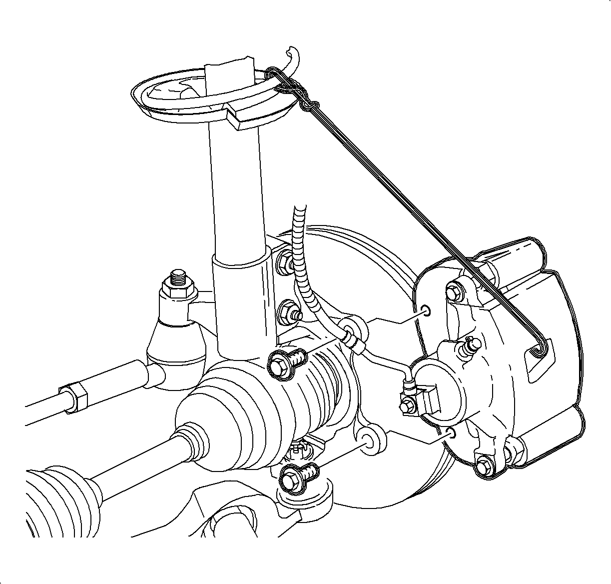
- Remove the caliper support to the steering knuckle bolts; remove the caliper assembly and suspend it from the strut spring with mechanics wire.
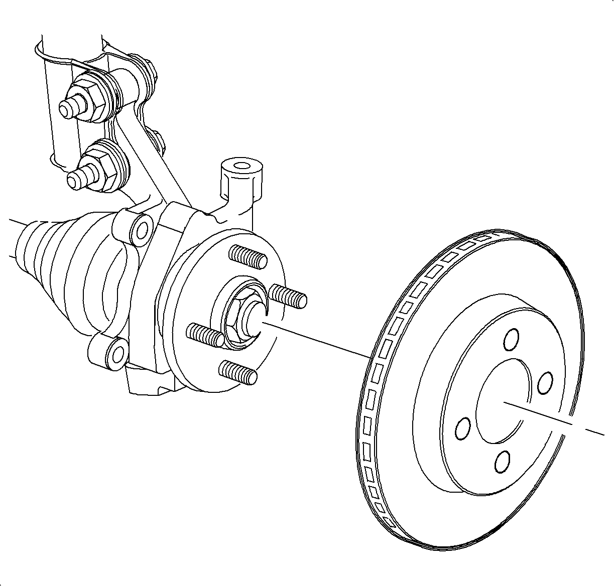
- Remove the rotor. Refer to Brake Rotor Surface and Wear Inspection .

Caution: Ensure that the vehicle is properly supported and squarely positioned. To help avoid personal injury when a vehicle is on a hoist, provide additional support for the vehicle on the opposite end from which the components are being removed.
Front Rotor Thickness
New: 180 mm (0.710 in)
Minimum After Turning: 16.1 mm (0.633 in)
Discard: 15.8 mm (0.625 in)
Installation Procedure
- Install the rotor onto the wheel hub.
- Install the caliper support onto the steering knuckle.
- Position the wheel onto the hub.
- Install the wheel nuts and tighten in a crisscross pattern. Repeat the tightening pattern to be sure the torque is correct.
- Lower the vehicle from the hoist.

Notice: Refer to Fastener Notice in the Preface section.
Important: Clean the caliper support bracket fasteners thoroughly with brake and choke cleaner. Use Saturn Brake Cleaner P/N 21007432 (or equivalent). Apply a high temperature thread locker (Loctite 272® or equivalent) to the caliper support bracket fasteners. If Loctite 272® (or equivalent) is not available, new caliper support bracket fasteners must be used.
Tighten
Tighten the brake caliper-to-steering knuckle to 110 N·m (81 lb ft).
Notice: Before installing wheels, remove rust or corrosion from wheel mounting surfaces and brake rotors/drums. Failure to do so can cause wheel nuts to loosen in service.
Tighten
Tighten the wheel nut to 140 N·m (103 lb ft).
