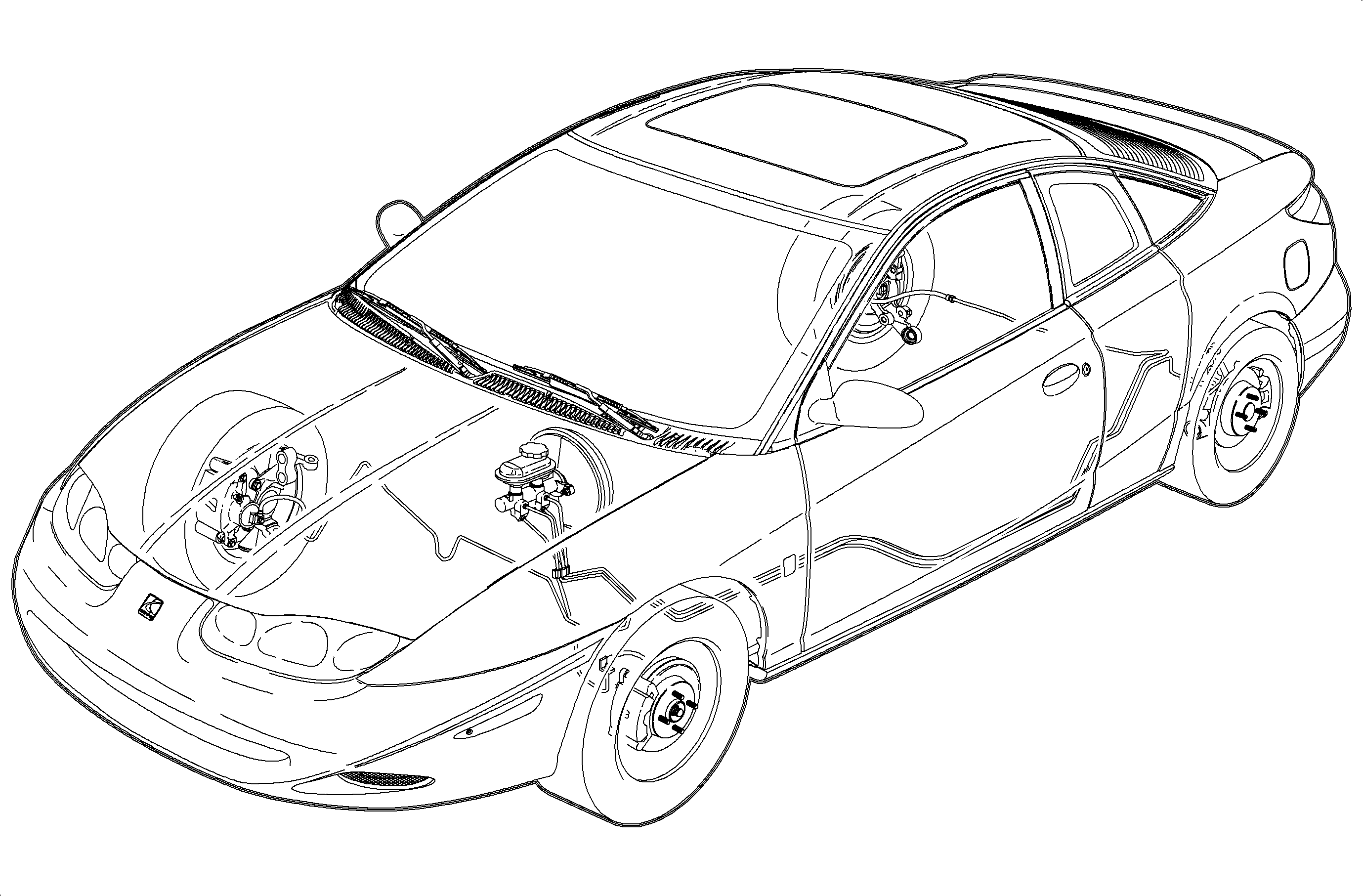
Conventional Brakes

Two braking systems are available for Saturn vehicles. The conventional (base) brake system consists of front disc brakes and rear drum brakes, with power assist. Optional is an antilock brake system (ABS). This section concerns itself with the conventional brake system.
The following descriptions explain the operation of the components used on the conventional brake system.
Master Cylinder
The master cylinder is a dual circuit unit designed for use in diagonally split hydraulic systems. With a diagonally split system, the left front and right rear brake are on one hydraulic circuit, while the right front and left rear are on the other.
Threaded into the master cylinder are integral brake proportioning valves, which limit the fluid pressure to the rear brakes after a predetermined rear brake pressure has been reached. These valves are used to minimize the occurrence of rear wheel lock-up when the brakes are applied and the vehicle is lightly loaded in the rear.
A brake fluid level switch, located in the brake fluid reservoir, attached to the master cylinder, is also provided. The switch will activate the RED BRAKE warning lamp, located on instrument panel, should the brake fluid level become low. After the brake fluid level is corrected and a moderately high brake pedal force is applied, the RED BRAKE warning lamp should go Off.
Vacuum Booster
The vacuum booster is a single diaphragm vacuum suspended unit. Engine vacuum is provided to the vacuum booster through a hose and a vacuum check valve. The one-way check valve is provided between the engine and the booster to prevent a loss of booster vacuum when engine vacuum falls below that stored in the booster. When the brakes are not applied, internal valves within the booster provide vacuum to both sides of the diaphragm. When the brakes are applied, air at atmospheric pressure is applied to one side of the diaphragm. Since a higher pressure now exists on one side of the diaphragm than the other, a force is created, assisting the brake application.
Front Caliper
Front calipers on Saturn vehicles are single piston, sliding caliper units; they are fastened to the caliper support with two bolts. Brake pressure, created in the master cylinder, acts equally on the caliper piston and caliper body (in the bottom of the caliper bore). This causes the piston to move outward (pushing the inboard brake pad against the brake rotor) and caliper body to slide inward (pushing the outboard brake pad against the brake rotor), creating stopping force. The front calipers are serviceable to the extent that they can be disassembled, cleaned, and fitted with new seals. However, since the piston bore cannot be honed, if extensive bore damage is present, the caliper body must be replaced.
Rear Drum Brake Assembly
The drum brake assembly is a leading/trailing shoe design. When the brakes are applied, the wheel cylinder moves both shoes out to contact the drum. With forward wheel rotation, the leading brake shoe provides the majority of the braking force, since it is self-energized, meaning that drum rotation draws the brake shoe into the drum. With reverse wheel rotation, the trailing brake shoe is self energized. Force from the brake shoes is transferred through the shoe anchor, the backing plate, the axle flange, and finally to the wheels. Brake adjustment is automatic, on any brake application. With leading/trailing brakes, it is normal for the leading (front) shoe to wear at a faster rate than the trailing (rear) shoe. The backing plate of the rear brake assembly has an inspection hole which allows for a quick visual inspection of the leading brake shoe/lining. A rubber plug covers the inspection hole to prevent dirt and moisture from entering the rear brake assembly.
Stop Lamp Switch
The stop lamp switch is located under the dashboard touching the brake pedal. The stop lamp switch is used to turn On the stop lamps and to serve as an input to the PCM and cruise control module, if equipped. The stop lamp switch has two internal independent switches; one is used for the stop lamps and the other for the PCM/cruise control module inputs. The switch for the PCM/cruise control module is normally closed (brake pedal released, plunger depressed) and the switch for the stop lamps is normally open (brake pedal released, plunger depressed). Ignition voltage is supplied to the PCM and the cruise control module through the stop lamp switch whenever the ignition is turned On and the brake pedal is released. When the brake pedal is depressed, the PCM/cruise control module inputs go low. The stop lamp switch is also used by the PCM as an input for transaxle downshifting and TCC operation.
For example, if the transaxle is in 2nd gear and the engine speed is low with the brake pedal depressed, the PCM will unlock the torque converter. The stop lamp switch can also aid in determining if a downshift should occur while going down a hill.
