Axle Shaft Oil Seal Replacement Left Side
Tools Required
| • | SA91100C Tie Rod Separator |
| • | SA91112T Axle Seal Protector |
| • | SA91113T Axle Seal Installer |
| • | SA9132S Lower Control Arm Ball Stud Separator |
| • | SA9133T Axle Seal Puller |
- Position the vehicle on the hoist.
- Raise the vehicle.
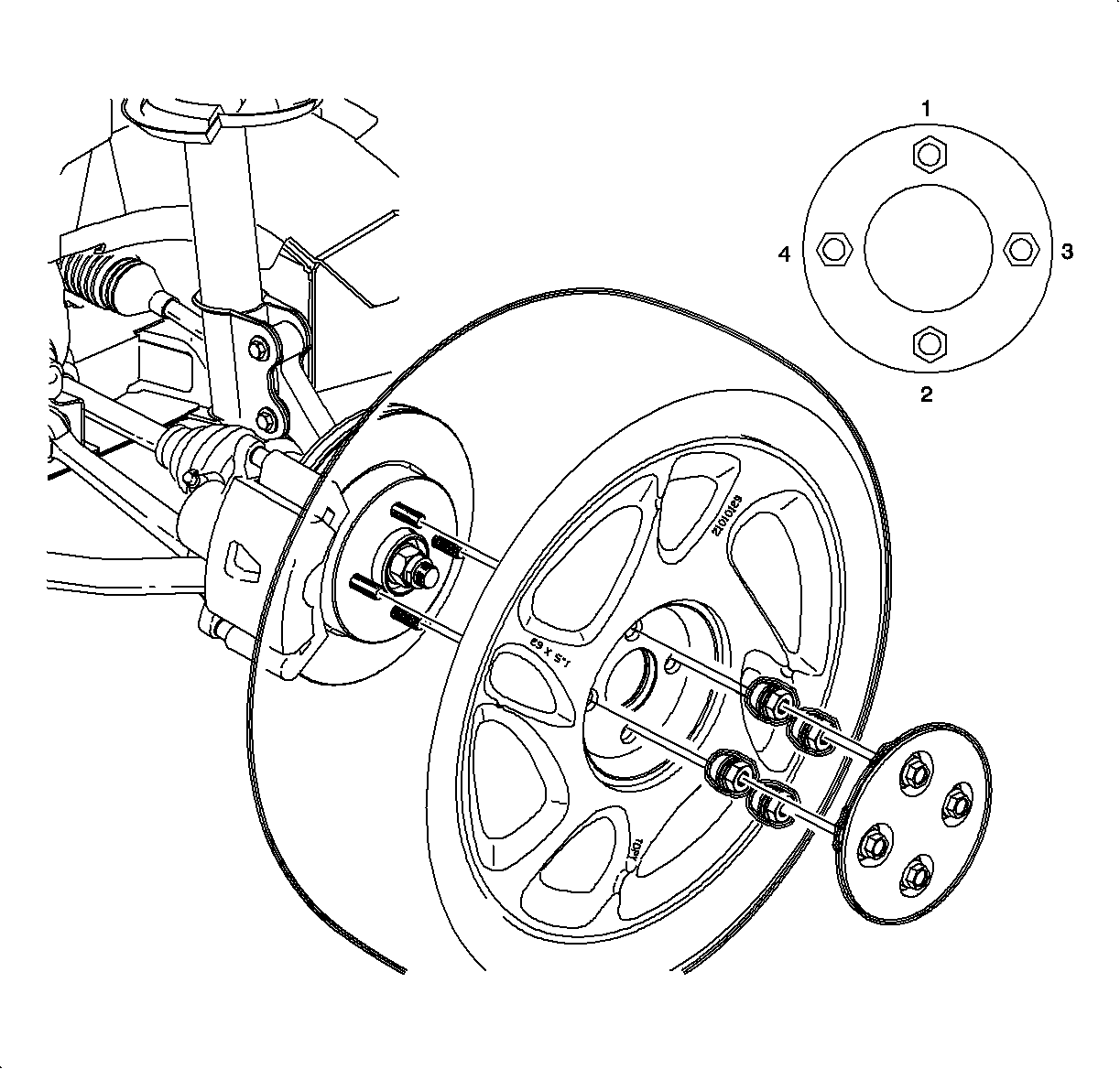
- Remove the left front wheel.
- Drain the transaxle fluid.
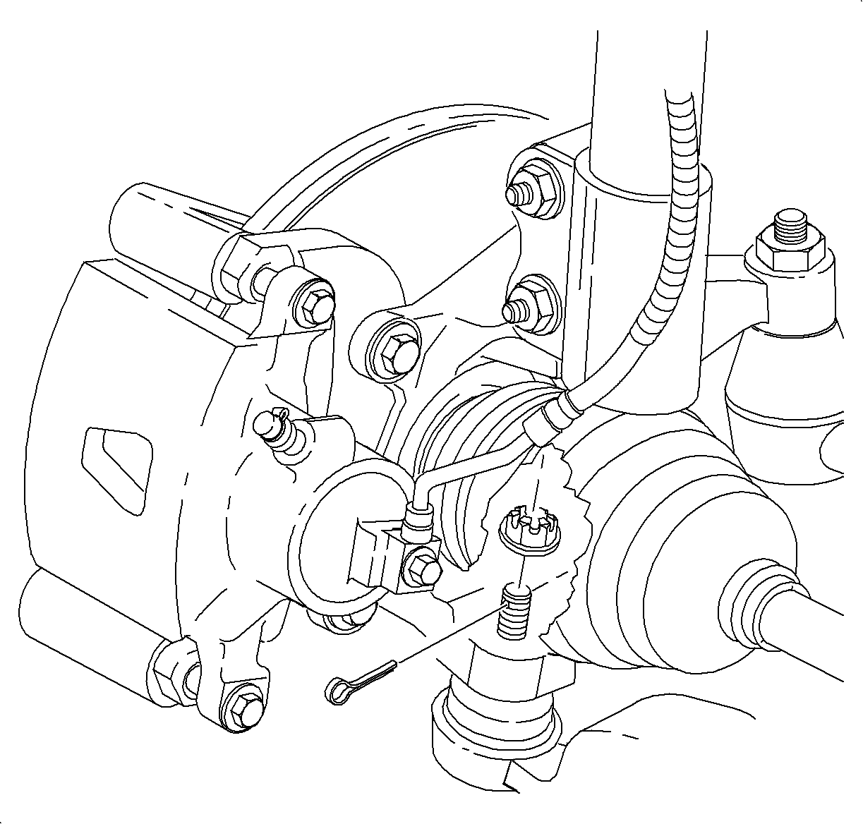
- Remove the cotter pin from the lower ball joint and discard. Loosen the nut and back off until the top of the nut is even with the top of the threads.
- Separate the ball joint from the steering knuckle using the SA9132S and remove the nut.
- Separate the tie rod end from the knuckle.
- Remove the left inner splash shield.
- Separate the axle from the transaxle using a large screwdriver or appropriate pry bar.
- Remove the axle seal retainer snap ring.
- Using the SA9133T , remove the seal by threading the puller through the steel seal body as close to the outside diameter as possible. Right side shown, left side similar.
Caution: Refer to Vehicle Lifting Caution in the Preface section.
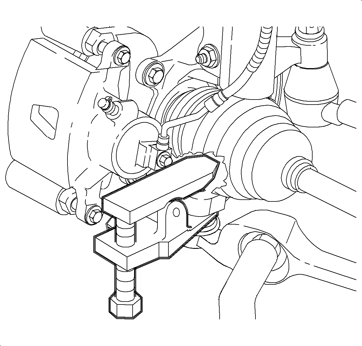
Notice: On ABS equipped vehicles, the outer CV joint has a speed sensor ring. Using the incorrect tool or procedure to separate the control arm from the knuckle can damage the ring, resulting in a loss of ABS operation.
Notice: Do not attempt to separate the joint using a wedge-type tool because seal may be damaged.
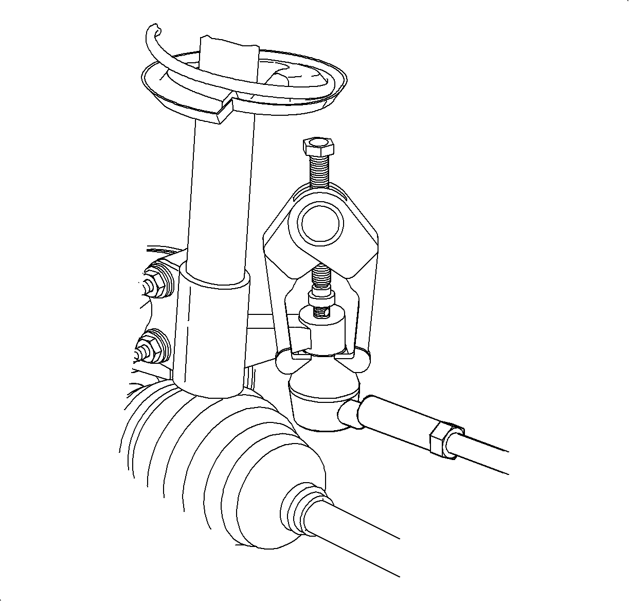
| 7.1. | Remove the cotter pin and discard. |
| 7.2. | Remove the nut. |
| 7.3. | Separate the tie rod end from the knuckle using the SA91100C . |
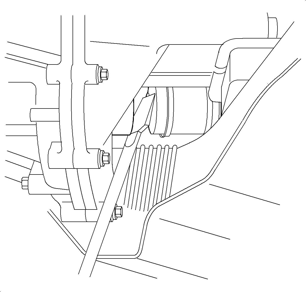
Notice: Be careful not to damage axle deflector ring.
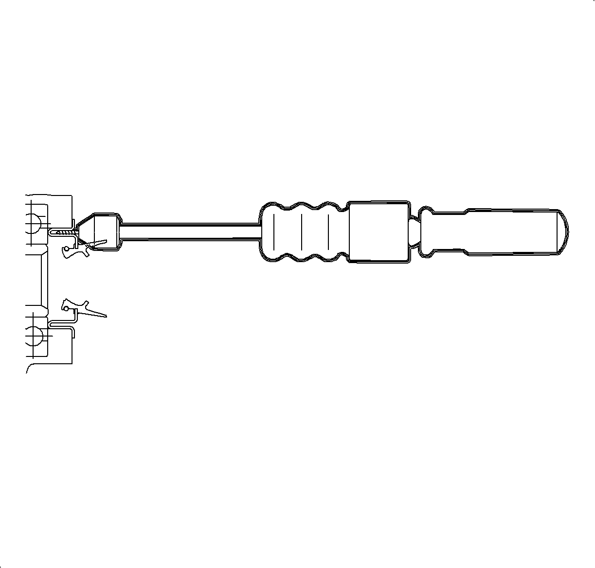
Installation Procedure
- Clean the seal bore in the housing.
- Apply a light bead of Loctite 515® Gasket Eliminator Sealant P/N 21005993 or equivalent on the diameter of the seal that presses into the case bore.
- Install the axle seal using the SA91113T . Place the seal on the tool and insert into the transaxle. Make sure to keep the seal lined up with the bore during installation. Automatic transaxle shown, manual transaxle similar.
- Install the axle seal retainer snap ring so that the retainer opening is easily accessible.
- Install the SA91112T , indicated by the arrow, inside the seal.
- Install the axle into the transaxle.
- After the shaft splines clear the seal, but before snapping the axle into place, remove the seal protector tool.
- Push the axle all the way into the transaxle.
- Clean and lubricate the ball joint threads.
- Position the ball joint into the steering knuckle.
- Install the nut to the lower ball joint and tighten.
- Clean and lubricate the threads on the tie rod end.
- Position the tie rod end into the steering knuckle.
- Install the nut to the tie rod end and tighten.
- Position the wheel onto the hub.
- Install the wheel nuts and tighten in a crisscross pattern. Repeat tightening procedure to make sure tighten is correct.
- Install the drain plug.
- Fill the transaxle to proper level using Saturn Transaxle Fluid.
- Check for proper fluid level using Transmission Fluid Check .
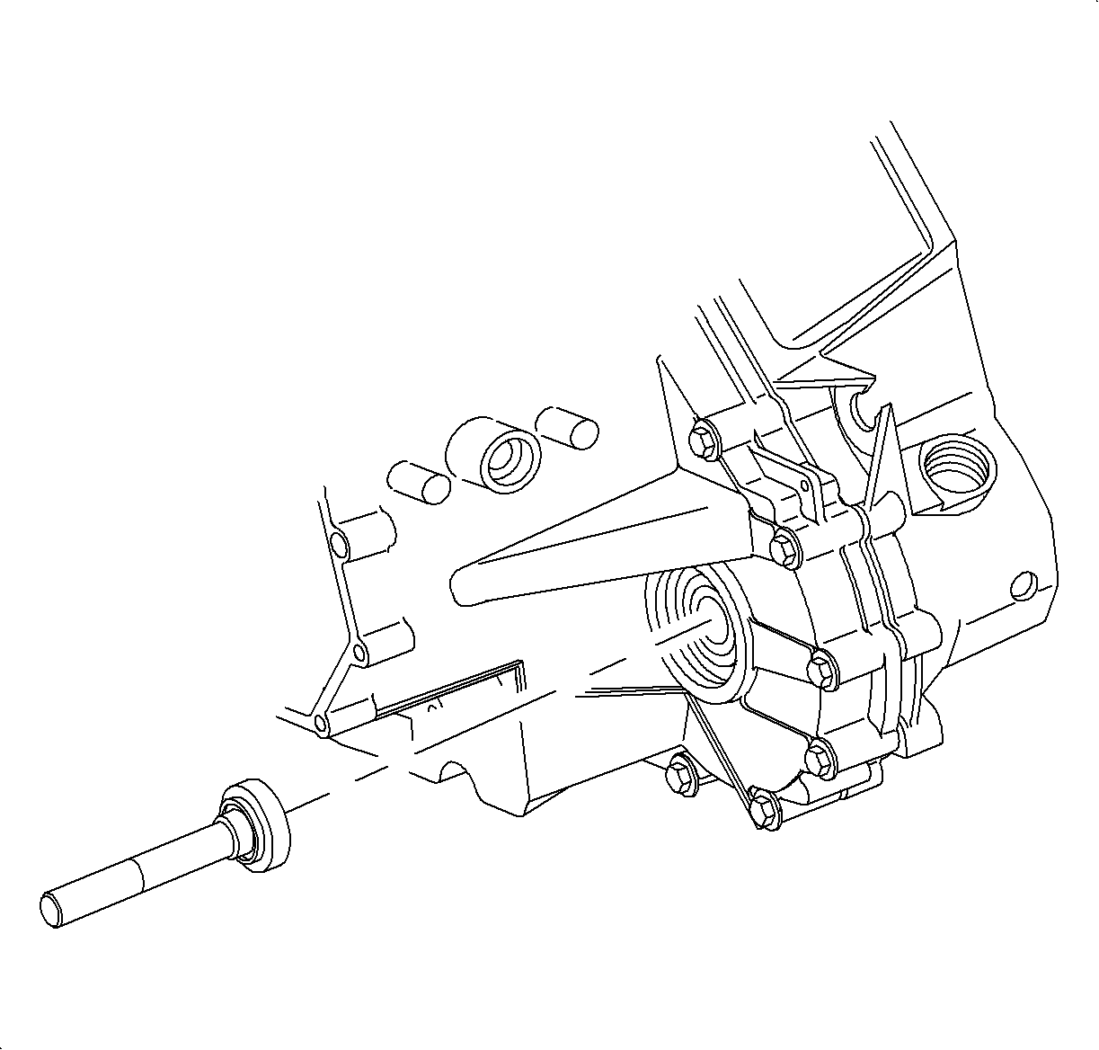
Notice: Prior to using Axle Seal Installer SA9113T inspect tool for any nicks or burrs that may damage seal lip.
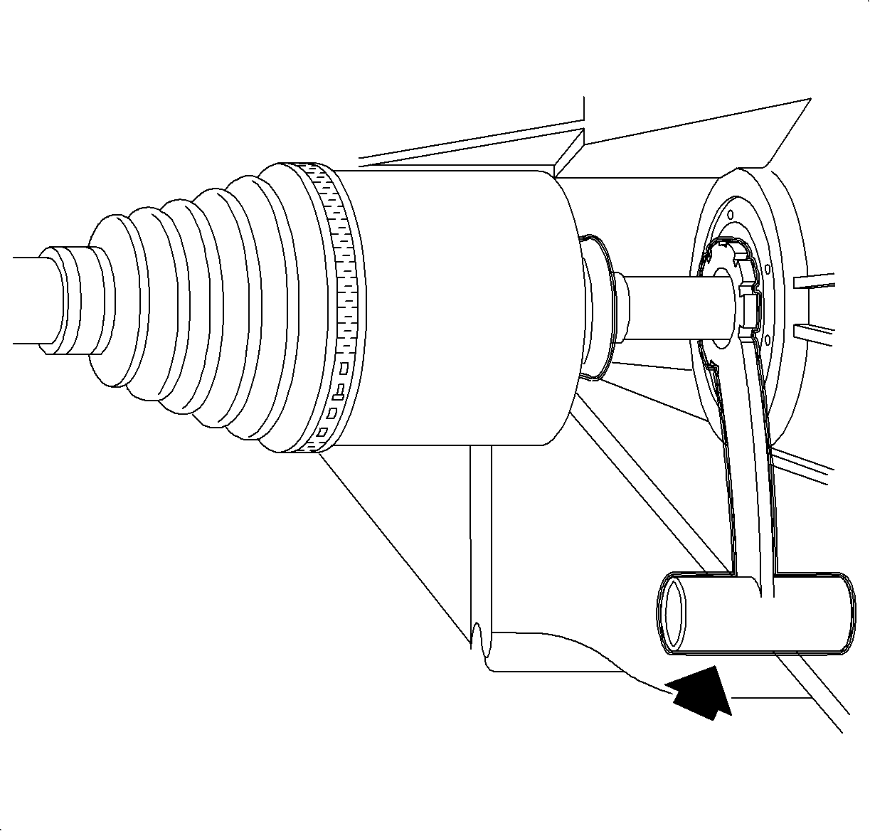
Notice: Use caution not to damage seal while installing axle into transaxle.

Notice: Take care not to damage rubber boot when installing ball joint to knuckle.
Notice: Refer to Fastener Notice in the Preface section.
Important: Align the slot in the nut to the cotter pin hole.
Tighten
Tighten the front lower control arm ball stud-to-steering knuckle nut to 75 N·m
(55 lb ft).
Important: If necessary, after tightening , tighten the nut additionally to align the slot in the nut with the cotter pin hole in the ball joint, and install a new cotter pin, and bend.
Tighten
Tighten the tie rod-to-steering knuckle nut to 25 N·m (19 lb ft)
+ 134°.

Notice: Before installing wheels, remove rust or corrosion from wheel mounting surfaces and brake rotors/drums. Failure to do so can cause wheel nuts to loosen in service.
Tighten
Tighten the wheel lug nuts in a crisscross patter to 140 N·m (103 lb ft).
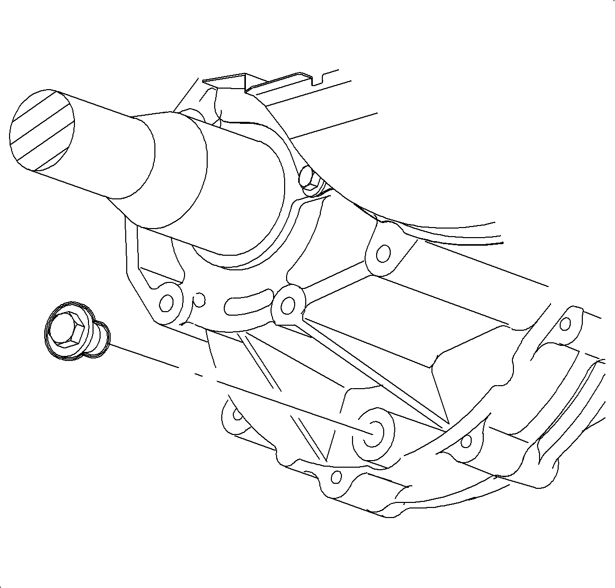
Important: Clean and lubricate the fastener with Saturn Transaxle Fluid. Wipe off excess fluid and install.
Tighten
Tighten the Transaxle drain plug to 30 N·m (22 lb ft).
Fill
Saturn Transaxle Fluid 2.5 L (2.6 qt)
Axle Shaft Oil Seal Replacement Right Side
Tools Required
| • | SA91100C Tie Rod Separator |
| • | SA91112T Axle Seal Protector |
| • | SA91113T Axle Seal Installer |
| • | SA9132S Lower Control Arm Ball Stud Separator |
| • | SA9133T Axle Seal Puller |
Removal Procedure
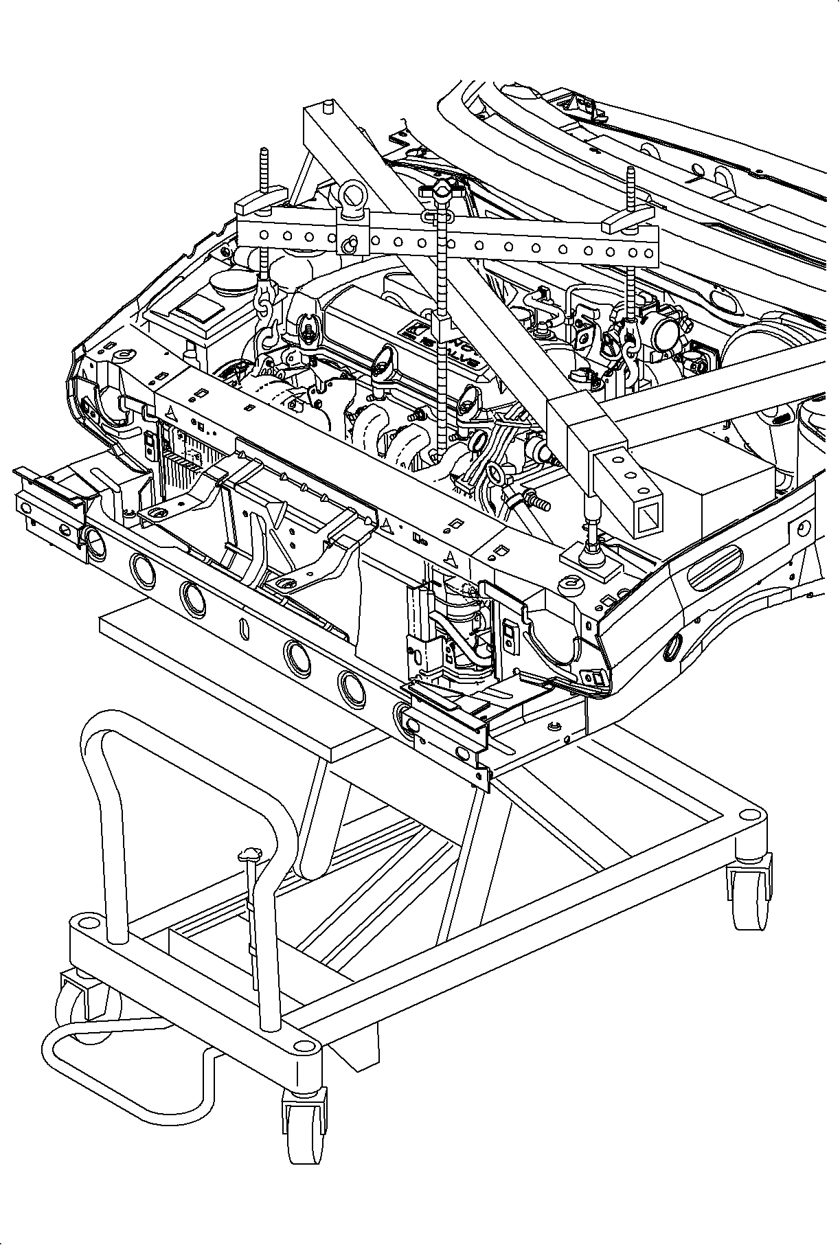
- Position the vehicle on the hoist.
- Raise the vehicle.
- Remove the right front wheel.
- Drain the transaxle fluid.
- Remove the cotter pin from the lower ball joint and discard. Loosen the nut and back off until the top of the nut is even with the top of the threads.
- Separate the ball joint from the steering knuckle using the SA9132S and remove the nut.
- Separate the tie rod end from the knuckle using the SA91100C .
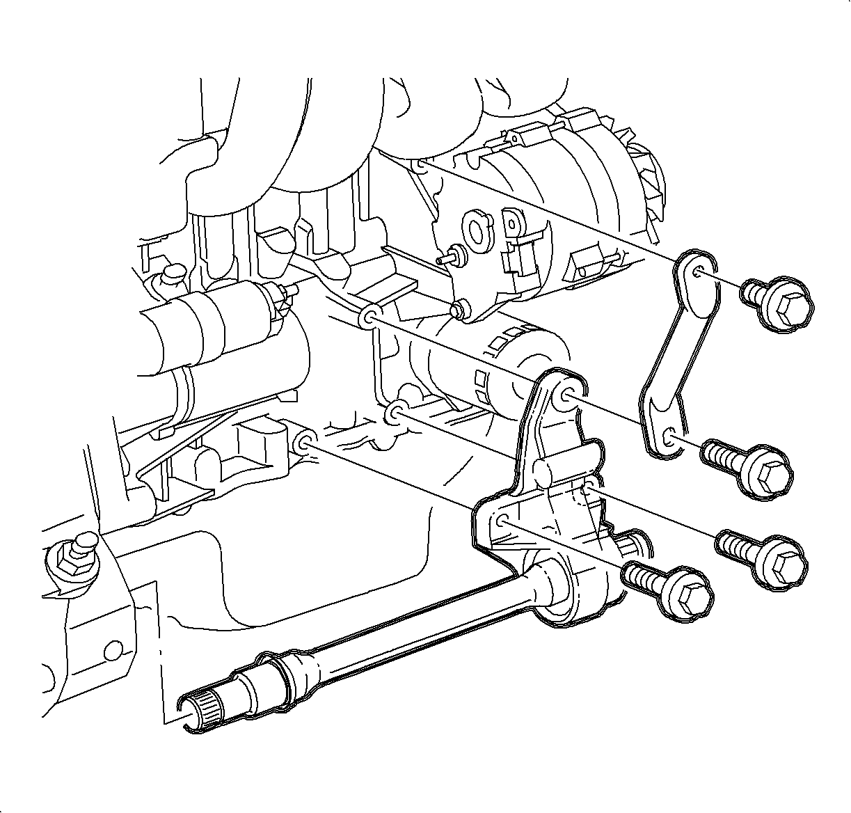
- Separate the right axle from the intermediate shaft.
- On DOHC (LLO) vehicles, remove the intake bracket to the intake manifold bolt.
- Remove the intake bracket to the intermediate shaft support bolt.
- Remove the two intermediate shaft to engine block bolts.
- Carefully slide the intermediate shaft out of the transaxle.
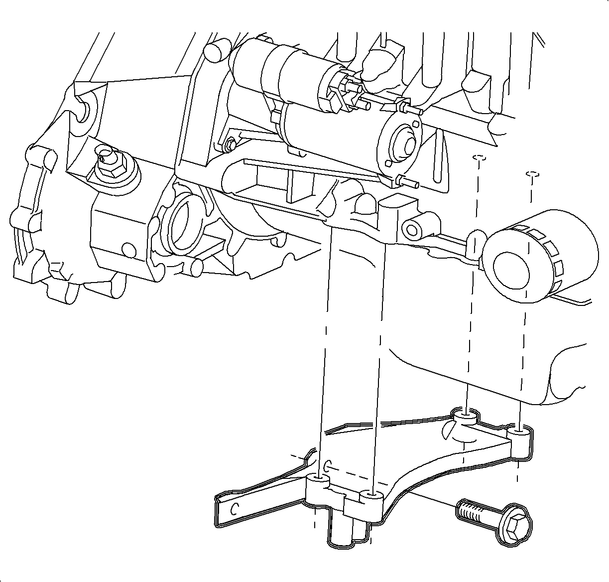
- Remove the engine to transaxle stiffening brace bolts and remove the brace.
- Remove the 3 flywheel housing dust cover bolts and remove the dust cover.
- Using the SA9133T , remove the seal by threading the puller through the steel seal body as close to the outside diameter as possible.
Caution: Refer to Vehicle Lifting Caution in the Preface section.


Notice: On ABS equipped vehicles, the outer CV joint has a speed sensor ring. Using the incorrect tool or procedure to separate the control arm from the knuckle can damage the ring, resulting in a loss of ABS operation.
Notice: Do not attempt to separate the joint using a wedge-type tool because seal may be damaged.

| 7.1. | Remove the cotter pin and discard. |
| 7.2. | Remove the nut. |
| 7.3. | Separate the tie rod end from the knuckle using the tie rod end separating tool. |

Installation Procedure
- Clean the seal bore in the housing.
- Apply a light bead of Loctite 515® Gasket Eliminator Sealant P/N 21005993 or equivalent on the diameter of the seal that presses into the bore.
- Use the tool SA91113T to install the seal. Place the seal on the tool and be sure to keep the seal lined up with the bore during installation. Automatic Transaxle shown, manual transaxle similar.
- Install the flywheel housing dust cover with the three bolts.
- Install the engine to transaxle stiffening brace and install the brace to engine, and brace to transaxle bolts.
- Install the SA9112T , indicated by the arrow, inside the seal.
- Install the intermediate shaft into the transaxle.
- After the splines clear the seal protector, but before snapping the axle into place, remove the seal protector tool.
- Position the intermediate shaft support and install the two bolts.
- On the DOHC (LLO) vehicles, position the intake manifold support bracket and install the intake bracket to the intake manifold bolt.
- Install the intake bracket to the intermediate shaft support bolt.
- Install the right axle to the intermediate shaft.
- Clean and lubricate the ball joint threads.
- Position the ball joint into the steering knuckle.
- Install the nut to the lower ball joint and tighten.
- Clean and lubricate the threads on the tie rod end.
- Position the tie rod end into the steering knuckle.
- Install the nut to the tie rod end and tighten.
- Position the wheel onto the hub.
- Install the wheel nuts and tighten in a crisscross pattern. Repeat tightening procedure to make sure tighten is correct.
- Install the drain plug.
- Fill the transaxle to the proper level using Saturn Transaxle Fluid.
- Check for proper fluid level using Transmission Fluid Check .
Notice: Prior to using Axle Seal Installer SA9113T inspect tool for any nicks or burrs that may damage seal lip.

Tighten
Tighten the flywheel housing cover-to-clutch housing bolts to 11 N·m
(8 lb ft).
Tighten
Tighten the engine-to-transaxle stiffening brace bolts to 54 N·m
(40 lb ft).

Notice: Use caution not to damage seal while installing axle into transaxle.
Left side shown, right side similar.

Tighten
Tighten the intermediate shaft support bracket-to-engine bolts to 54 N·m
(40 lb ft).
Tighten
Tighten the intake manifold support bracket-to-manifold bolt (LLO) to 30 N·m
(22 lb ft).
Tighten
Tighten the intake manifold support bracket-to-intermediate shaft support bracket
nut (LLO) to 54N·m (40 lb ft).

Notice: Take care not to damage rubber boot when installing ball joint to knuckle.
Tighten
Tighten the front lower control arm ball stud-to-steering knuckle nut to 75 N·m
(55 lb ft).
If necessary, after tightening, tighten the nut additionally to align the slot in the nut with the cotter pin hole in the ball joint and install a new cotter pin and bend.

Tighten
Tighten the tie rod-to-steering knuckle nut to 25 N·m (18 lb ft)
+ 134°.
Notice: Before installing wheels, remove rust or corrosion from wheel mounting surfaces and brake rotors/drums. Failure to do so can cause wheel nuts to loosen in service.
Tighten
Tighten the wheel lug nuts in a crisscross patter to 140 N·m (103 lb ft).

Important: Clean and lubricate the fastener with Saturn Transaxle Fluid. Wipe off excess fluid and install.
Tighten
Tighten the transaxle drain plug to 30 N·m (103 lb ft).
Fill
Saturn Transaxle Fluid 2.5 L (2.6 qt)
