Tools Required
J 22610 Clamp Pliers
Removal Procedure
- Raise vehicle on hoist.
- Remove wheel and tire.
- Remove outer tie rod end as previously described.
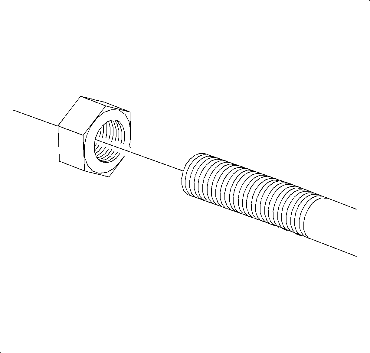
- Remove inner tie rod-to-outer tie rod lock nut from inner tie rod.
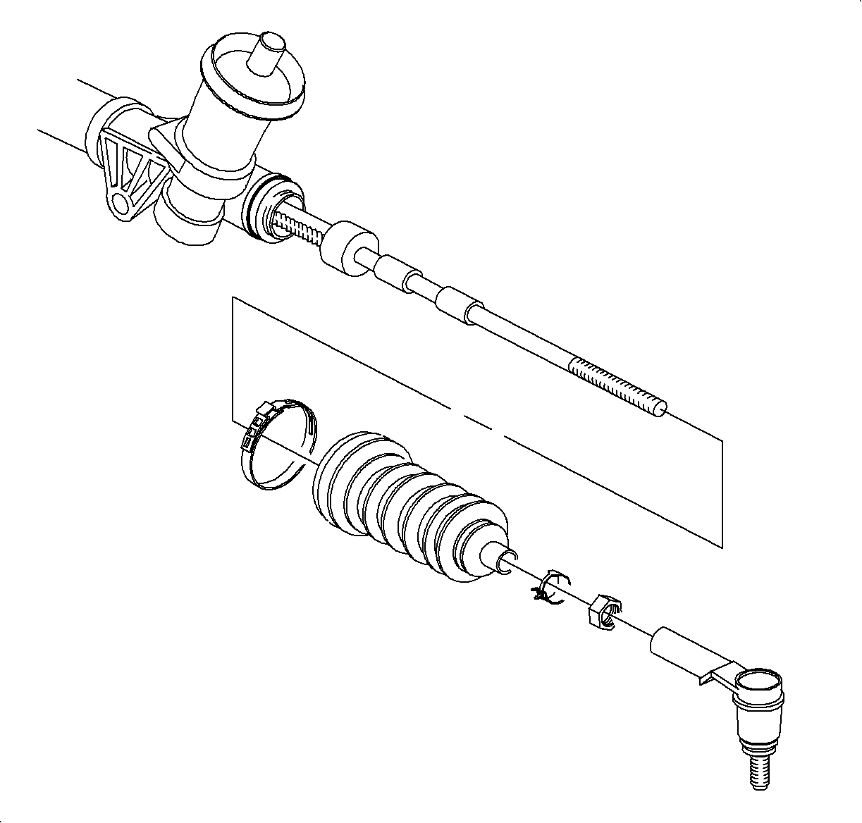
- Remove boot clamp (tie rod end).
- Remove boot clamp (steering gear housing end) with cutters and discard.
- Remove steering gear boot from steering gear.

Caution: Ensure that the vehicle is properly supported and squarely positioned. To help avoid personal injury when a vehicle is on a hoist, provide additional support for the vehicle on the opposite end from which the components are being removed.
Important: Removal of splash shield makes access easier.

Installation Procedure
- Install new boot clamp onto steering gear boot (steering gear housing end).
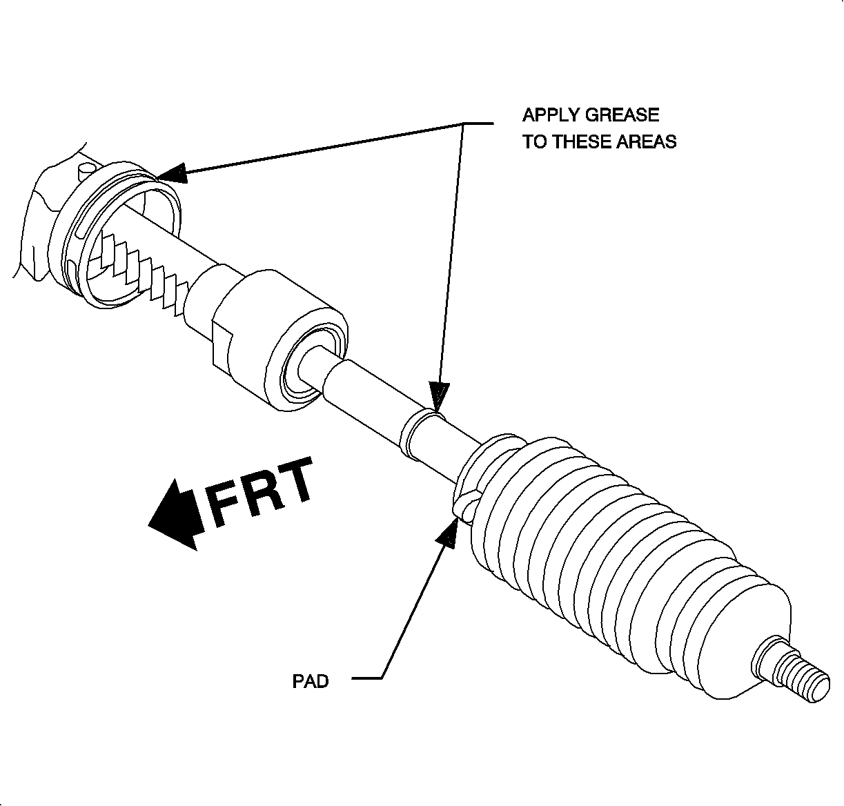
- Apply grease in service kit to locations shown in illustration prior to boot installation. This grease provides a water barrier and must be used to protect internal gear components from corrosion.
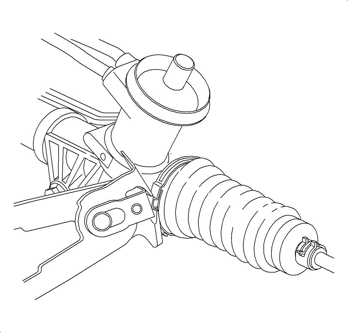
- Install boot onto inner tie rod assembly, then slide boot along rod assembly until the large end of the boot is seated in the steering gear housing groove.
- Crimp clamp on housing end of boot using J 22610 .
- Install clamp on inner tie rod end of boot using J 22610 .
- Install inner tie rod-to-outer tie rod lock nut.
- Install outer tie rod and attach to knuckle as previously described.
- Position wheel onto hub.
- Install wheel nuts and tighten in a crisscross pattern. Repeat tightening pattern to make sure torque is correct.
- Set toe. Refer to Wheel Alignment Specifications in Wheel Alignment.

Important: The boot has a small pad near the clamp location on the housing end. The boot should be turned so that the pad is toward the front of the vehicle.
Important: Boot must not be twisted or puckered.

Tighten
Tighten Tie Rod Lock Nuts 70 N·m (35 lbs ft).
Notice: Before installing wheels, remove rust or corrosion from wheel mounting surfaces and brake rotors/drums. Failure to do so can cause wheel nuts to loosen in service.
Tighten
Tighten Wheel Nuts 140 N·m (103 lbs ft).
