Air Conditioning Compressor Hose Replacement Compressor Suction Hose
Removal Procedure
- Recover the refrigerant using an approved refrigerant recovery system.
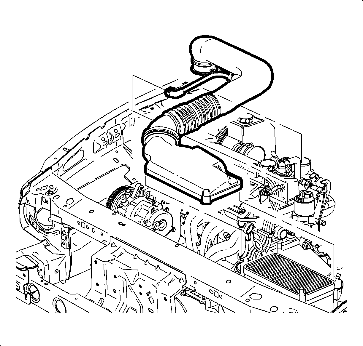
- Remove the air cleaner cover and the air induction hose at the intake manifold.
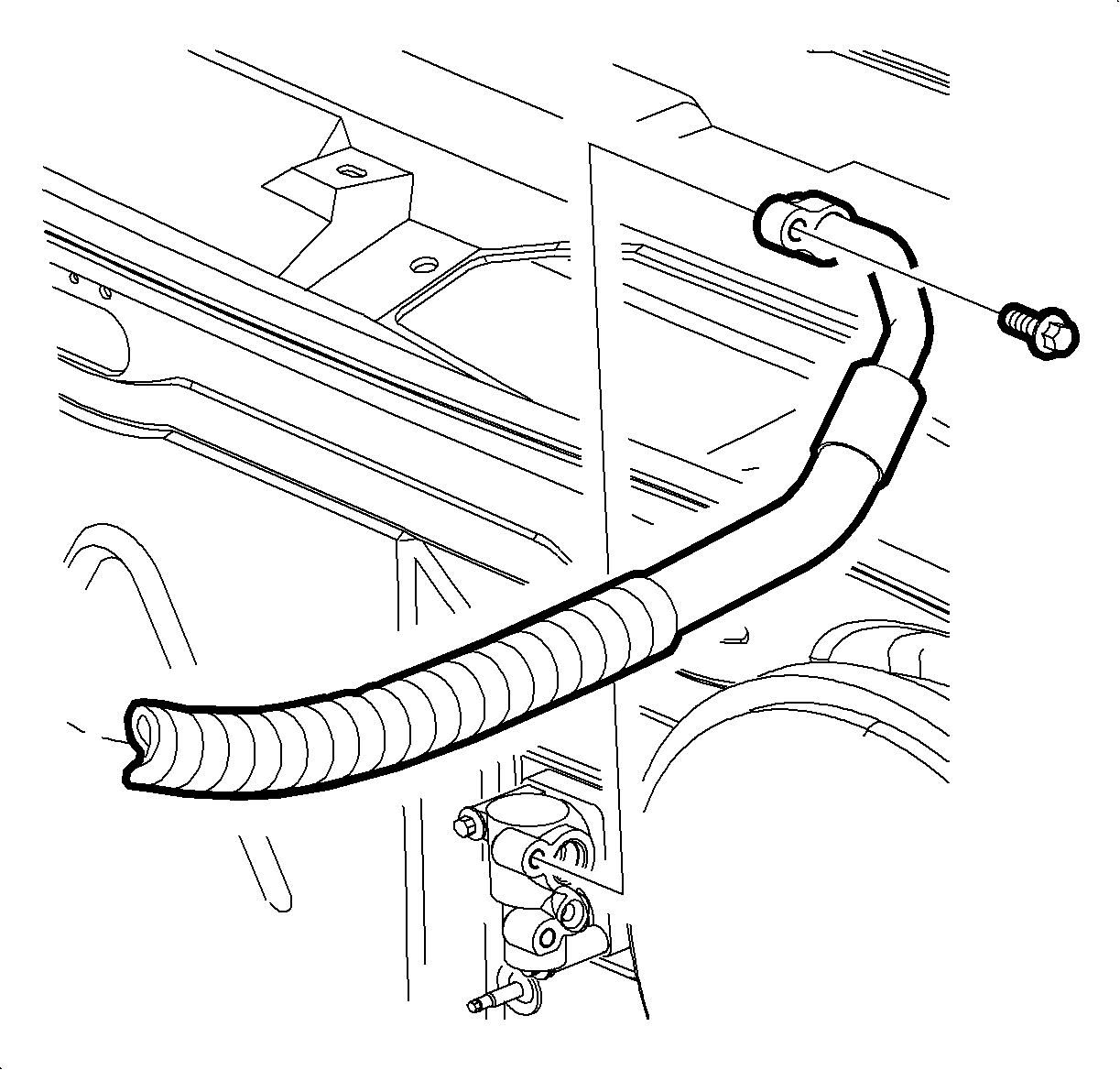
- Remove the suction hose from the thermal expansion valve (TXV).
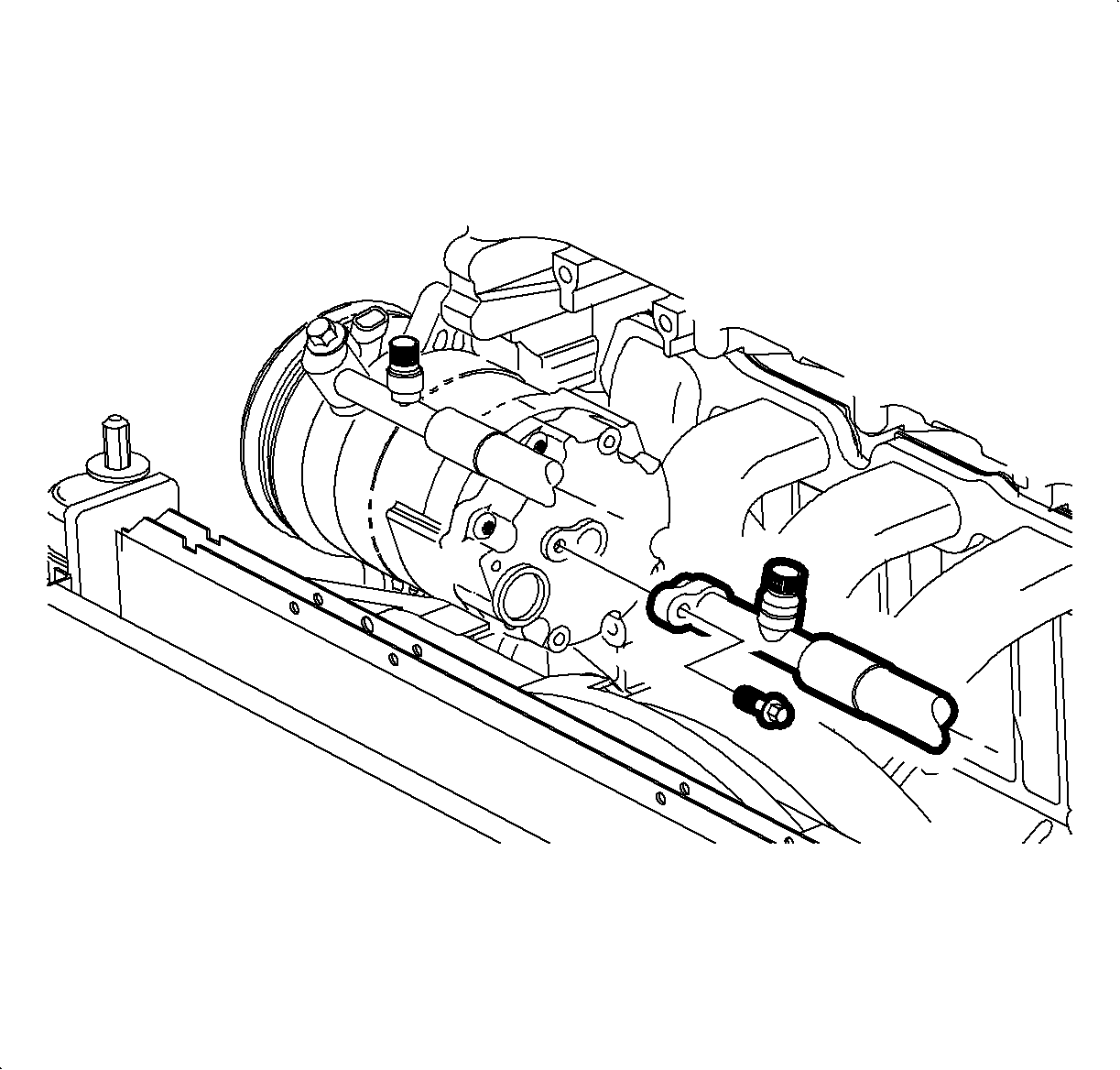
- Remove the suction hose from the compressor inlet.
- Remove the suction hose from the vehicle.
Installation Procedure
- Remove the protective cover from the suction hose.
- Install the suction hose to the compressor inlet.
- Install and tighten the bolt.
- Route the hose around the outside of the transaxle dip stick tube, under the edge of the battery tray, and under the negative battery cable.
- Remove the protective cover.
- Lubricate the O-ring with R-12 Refrigerant mineral oil.
- Install the suction hose to the TXV.
- Install and tighten the bolt.
- Install the air cleaner components.

Important: Do not lubricate the new slim line seal washer on the compressor side of the suction hose. The slim line seal washer cannot be interchanged with a typical O-ring in the A/C system. Use only suction line slim line seal washers as a replacement.
Notice: Refer to Fastener Notice in the Preface section.
Tighten
Tighten the suction hose-to-compressor to 25 N·m (19 lb ft).
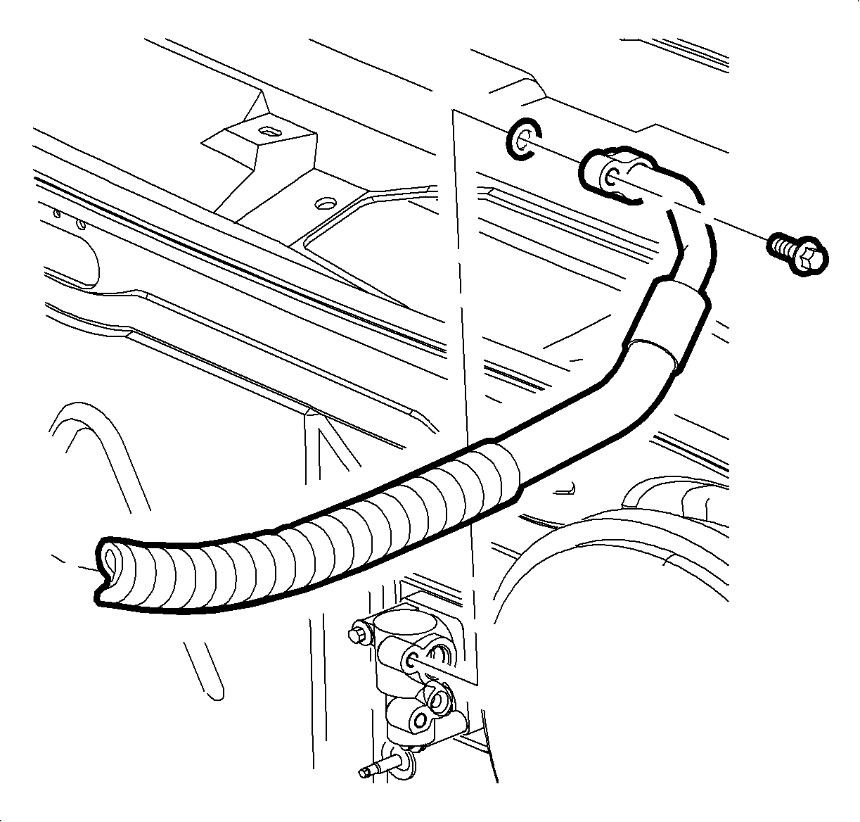
Notice: Use only Polyalkylene Glycol Synthetic Refrigerant Oil (PAG) for internal circulation through the R-134a A/C system and only 525 viscosity mineral oil on fitting threads and O-rings. If lubricants other than those specified are used, compressor failure and/or fitting seizure may result.
Tighten
Tighten the suction hose-to-thermal expansion valve to 25 N·m (19 lb ft).
Air Conditioning Compressor Hose Replacement Compressor Discharge Hose
Removal Procedure
- Recover the refrigerant using an approved refrigerant recovery system.
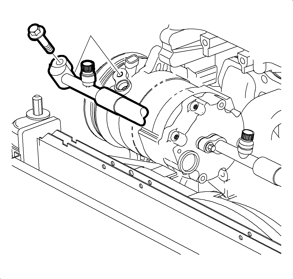
- Remove the discharge hose from the compressor outlet.
- Remove the left front headlamp assembly to gain access to the condenser inlet fitting.
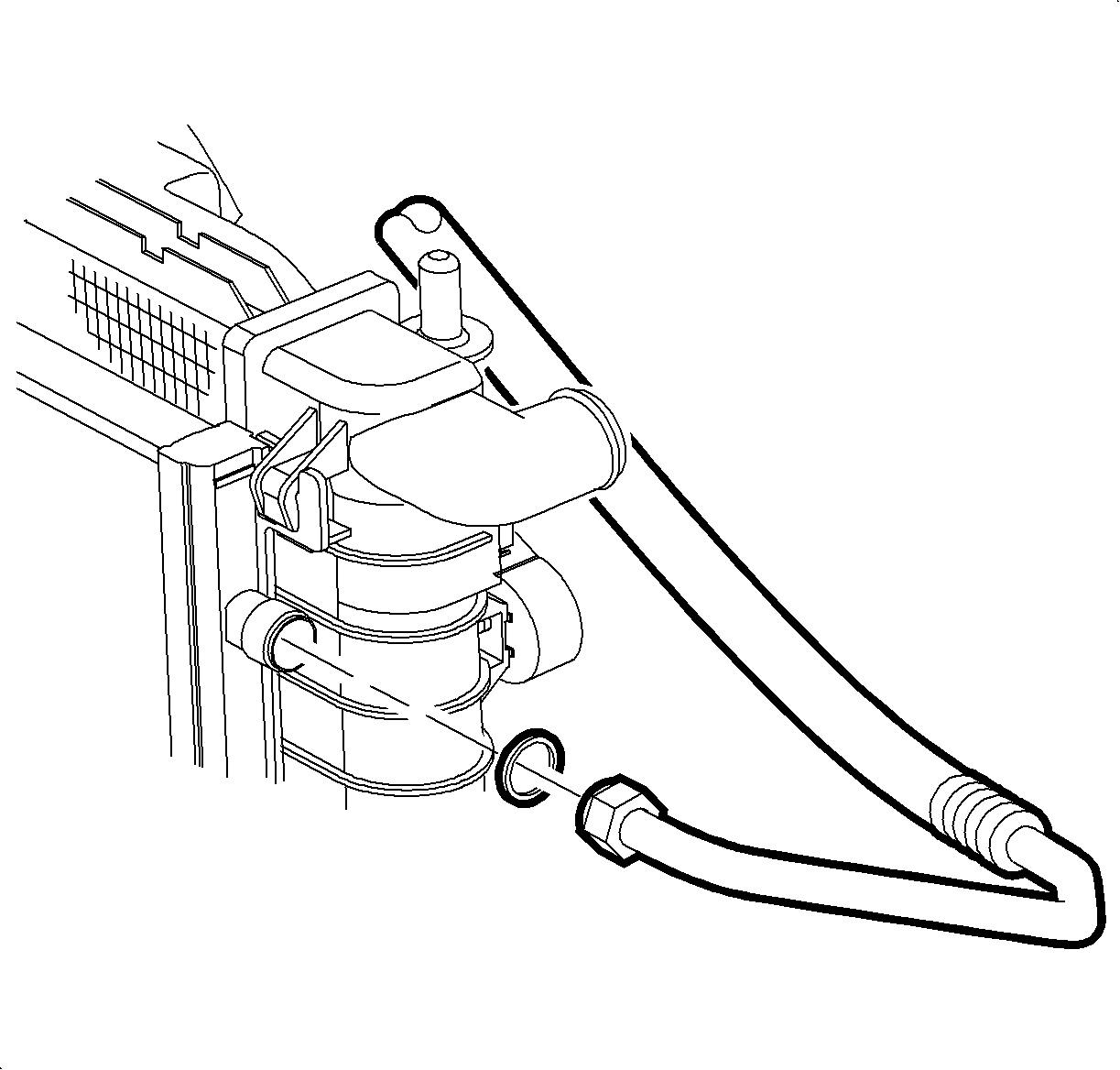
- Remove the discharge hose from the condenser inlet.
Installation Procedure
- Remove the protective cover from the discharge hose.
- Lubricate the O-ring with R-12 Refrigerant mineral oil.
- Install the discharge hose to the condenser inlet.
- Tighten the fitting.
- Install the left front headlamp assembly.
- Remove the protective cover from the discharge hose.
- Lubricate the O-ring with R-12 Refrigerant mineral oil.
- Install the discharge hose to the compressor.
- Install and tighten the bolt.
- Evacuate, charge, and leak test the A/C system.
Notice: Use only Polyalkylene Glycol Synthetic Refrigerant Oil (PAG) for internal circulation through the R-134a A/C system and only 525 viscosity mineral oil on fitting threads and O-rings. If lubricants other than those specified are used, compressor failure and/or fitting seizure may result.
Notice: Refer to Fastener Notice in the Preface section.
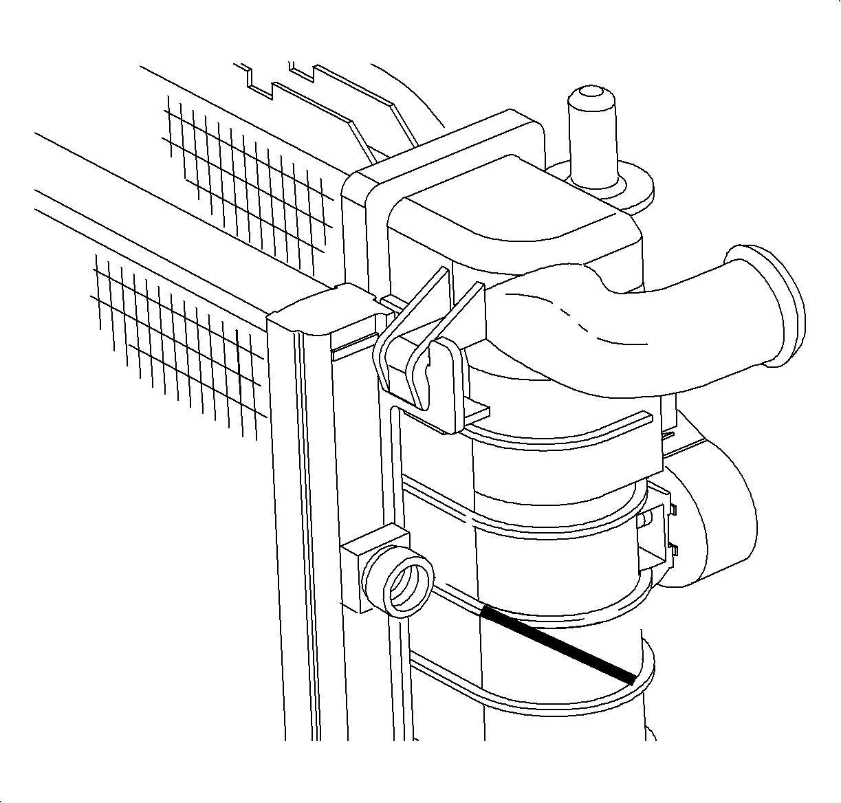
Important: Make sure the discharge hose pipe is parallel to the line on the radiator end tank. This will prevent the discharge hose from contacting the suction hose and transaxle oil cooler lines, preventing potential damage to the hoses.
Tighten
Tighten the discharge hose-to-condenser inlet to 23.5 N·m (17 lb ft).

Notice: Use only Polyalkylene Glycol Synthetic Refrigerant Oil (PAG) for internal circulation through the R-134a A/C system and only 525 viscosity mineral oil on fitting threads and O-rings. If lubricants other than those specified are used, compressor failure and/or fitting seizure may result.
Tighten
Tighten the discharge hose-to-compressor to 25 N·m (19 lb ft).
Air Conditioning Compressor Hose Replacement Liquid Line
Removal Procedure
- Recover the refrigerant using an approved refrigerant recovery system.
- Disconnect the negative battery cable.
- Disconnect the positive battery cable.
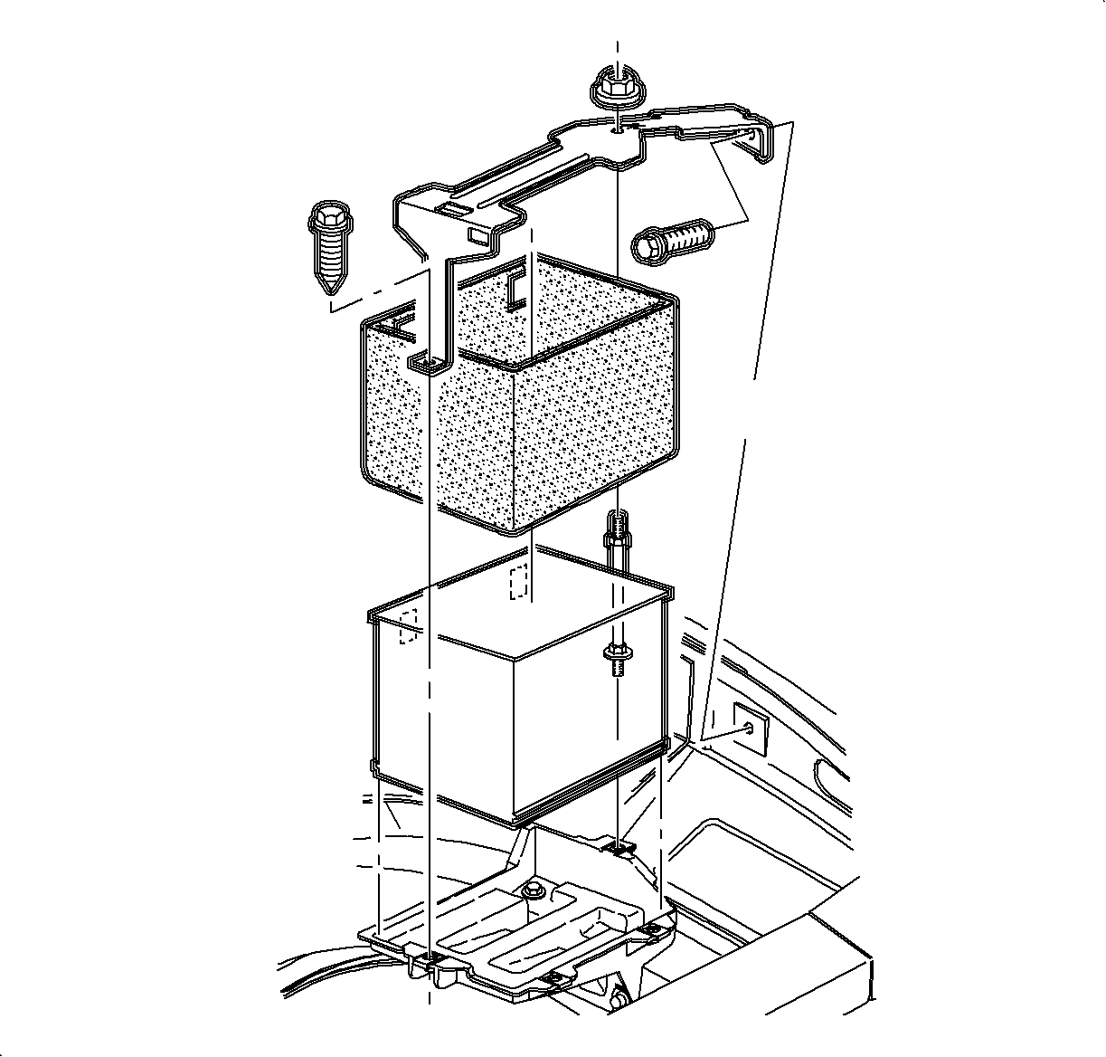
- Remove the hold-down retaining nut and screws and lift off the battery hold-down retainer.
- Remove the air cleaner housing cover and the air induction hose at the intake manifold.
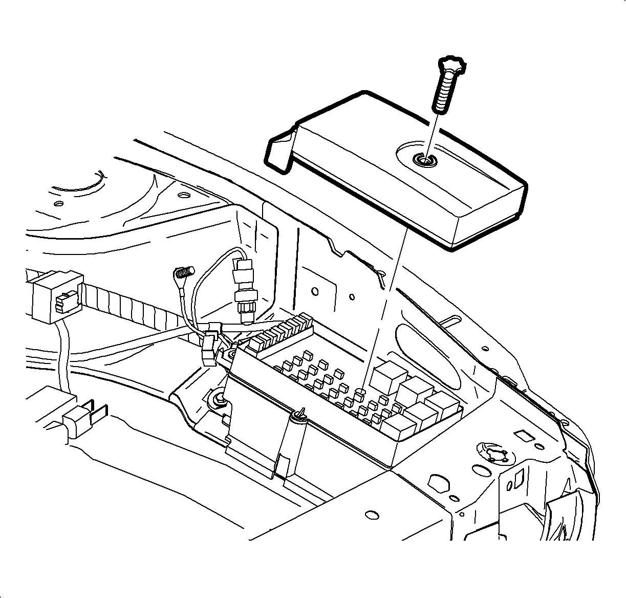
- Remove the underhood fuse block cover.
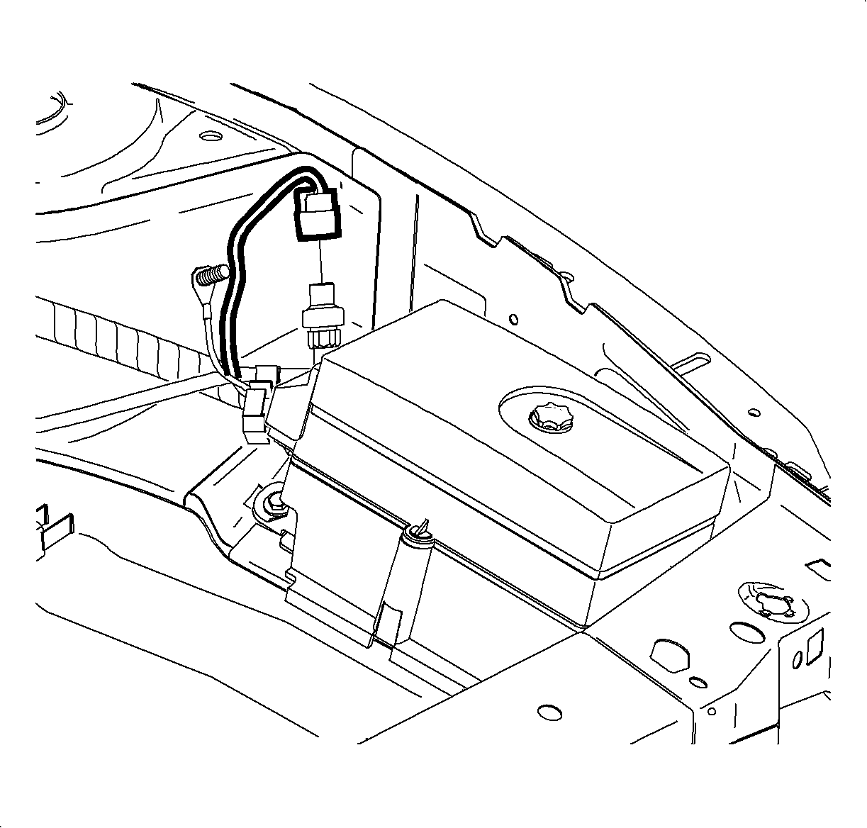
- Disconnect the electrical harness from the pressure sensor.
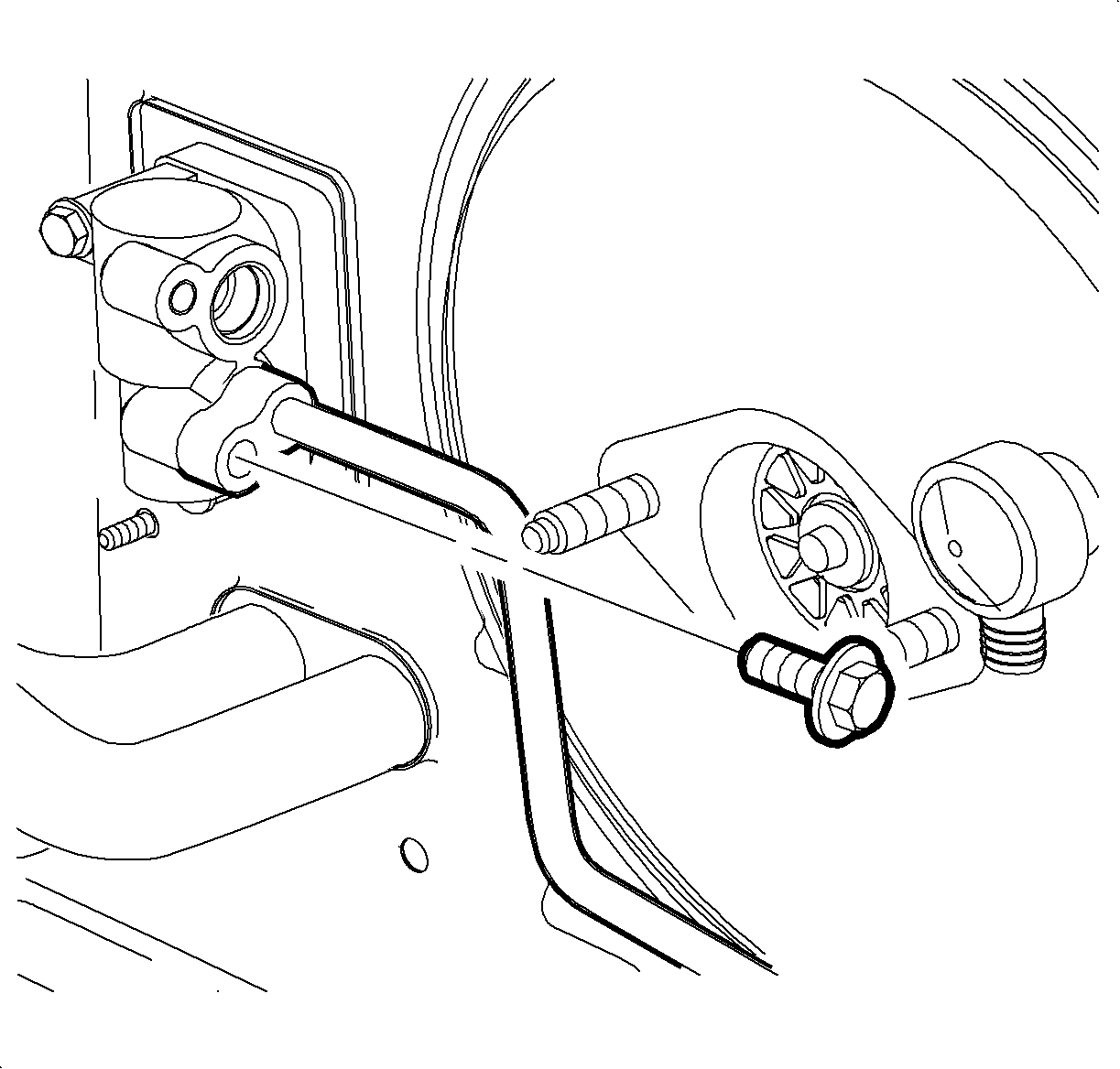
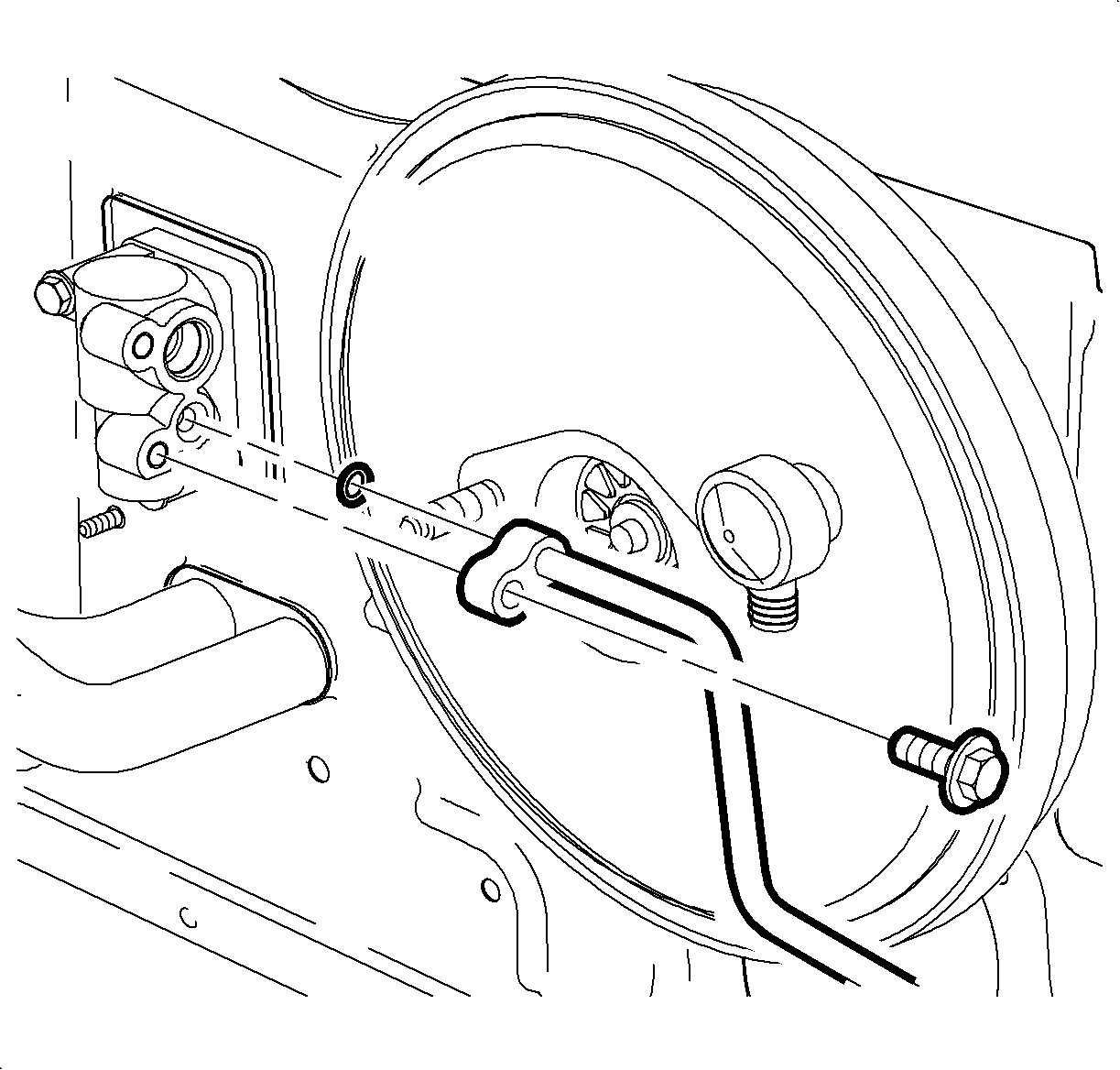
- Remove the bolt holding the liquid line to the thermal expansion valve (TXV).
- Raise the vehicle.
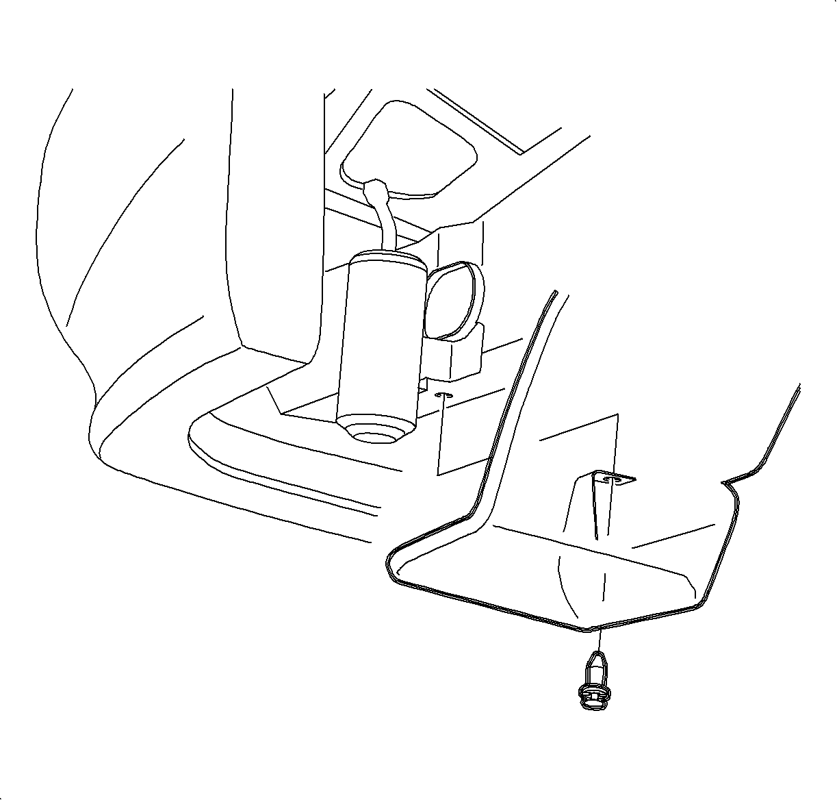
- Remove the push nut and pull back the receiver-dehydrator splash shield.
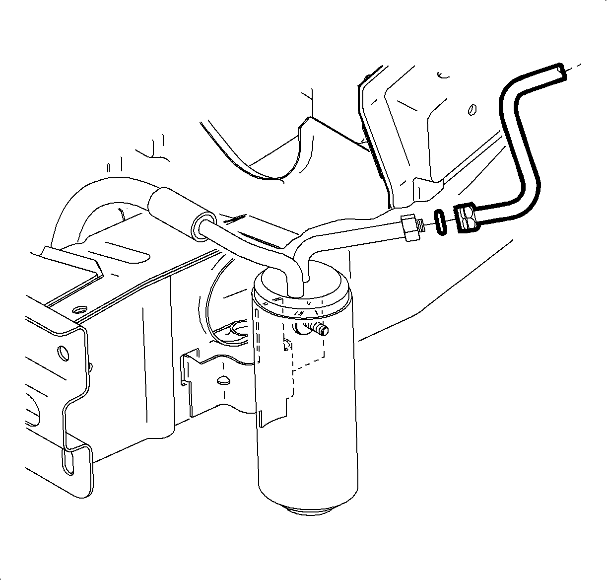
- Disconnect the liquid line from the receiver-dehydrator.
- Lower the vehicle.
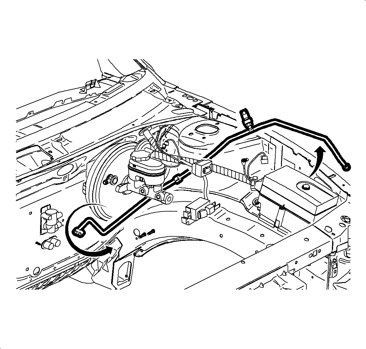
- Remove the liquid line from the hold down clamps, lift the receiver-dehydrator end of the liquid line clear of the underhood fuse block.
- Lift and rotate the TXV end of the liquid line counterclockwise to remove from the vehicle.
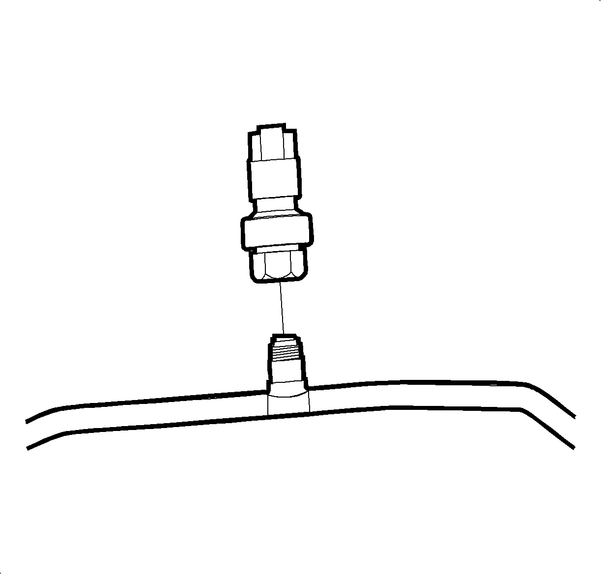
- Remove the pressure sensor from the liquid line.
Caution: Refer to Battery Disconnect Caution in the Preface section.

Caution: To avoid any vehicle damage, serious personal injury or death when major components are removed from the vehicle and the vehicle is supported by a hoist, support the vehicle with jack stands at the opposite end from which the components are being removed and strap the vehicle to the hoist.
Installation Procedure
- Remove the protective cover from the liquid line switch port and lubricate the O-ring.
- Install the pressure switch to the liquid line and tighten to specifications.
- Place tape around the protective cover on the TXV end of the liquid line to keep the cover from falling off during installation.
- Hold the liquid line as shown. Use the pressure switch as a frame of reference.
- Lower the TXV end of the line down behind the left strut tower against the cowl.
- Rotate the line clockwise while feeding the line under and behind the brake booster.
- Continue feeding the line along the cowl towards the TXV while lowering the receiver drier end down to the radiator support.
- Lower the liquid line past the wiring harness and the hood release cable.
- Lower the hood support rod.
- Move the receiver drier end of the line around the hood support rod and the fuse box.
- Insert the driver end of the line through the body cut out.
- Remove the tape and protective cover from the TXV end of the liquid line.
- Lubricate the O-ring with R-12 Refrigerant mineral oil.
- Install the line and bolt to the TXV. Tighten the bolt.
- Raise the vehicle.
- Remove the protective cover and lubricate the O-rings with R-12 Refrigerant mineral oil.
- Connect the liquid line to the receiver-dehydrator. Tighten the fitting.
- Rotate the receiver-dehydrator splash shield into place and install the push nut.
- Lower the vehicle.
- Connect the electrical harness to the pressure sensor.
- Install the underhood fuse block cover and hand tighten the screw.
- Install the battery hold-down retainer, locking the battery into the tray.
- Install the battery hold-down retainer nut and screws.
- Install the air cleaner housing cover and the air induction hose.
- Connect the positive battery cable first.
- Connect the negative battery cable last.
- Evacuate, charge and leak test the A/C system.
- Set the clock to the proper time, if equipped.

Notice: Use only Polyalkylene Glycol Synthetic Refrigerant Oil (PAG) for internal circulation through the R-134a A/C system and only 525 viscosity mineral oil on fitting threads and O-rings. If lubricants other than those specified are used, compressor failure and/or fitting seizure may result.
Notice: Refer to Fastener Notice in the Preface section.
Tighten
Tighten the A/C hi/lo pressure switch to 5.5 N·m (49 lb in).
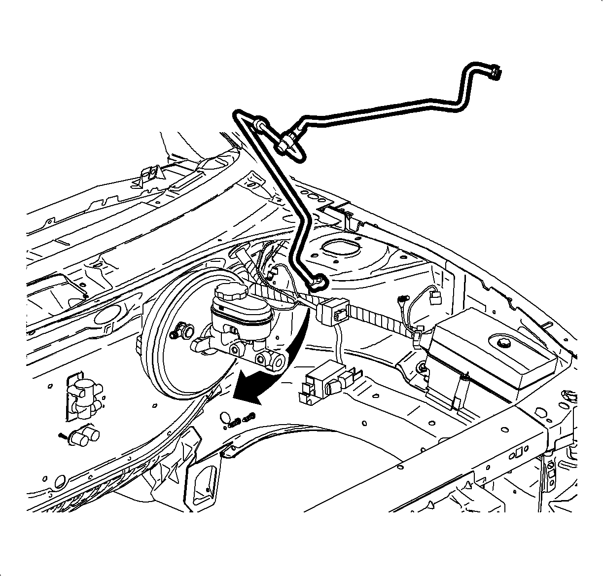
Important: Make sure the line is behind the clutch slave cylinder hose if equipped with a manual transaxle.
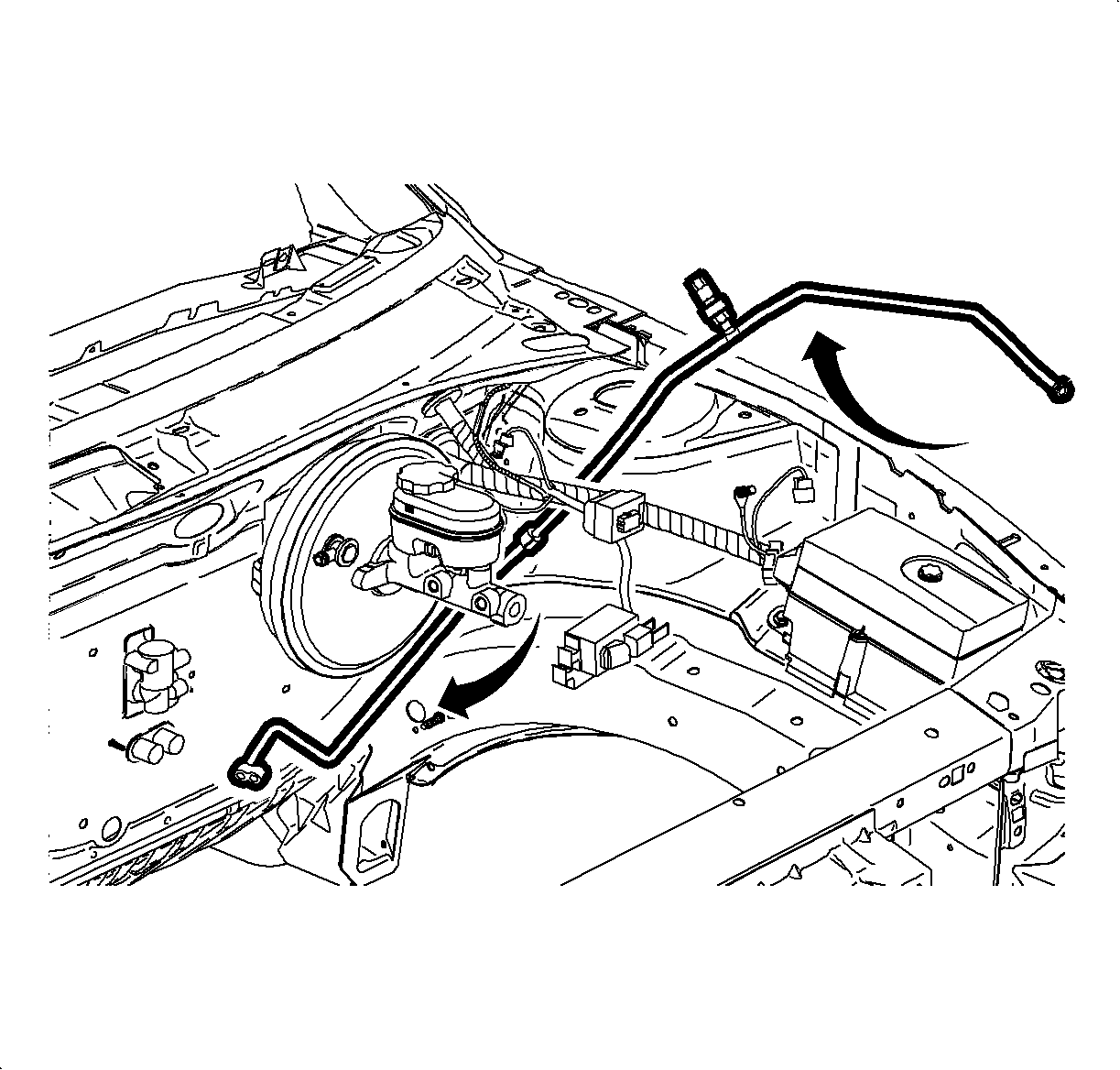
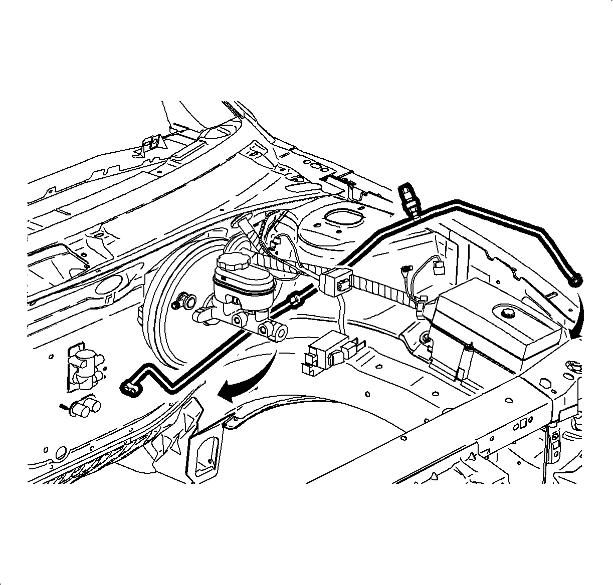
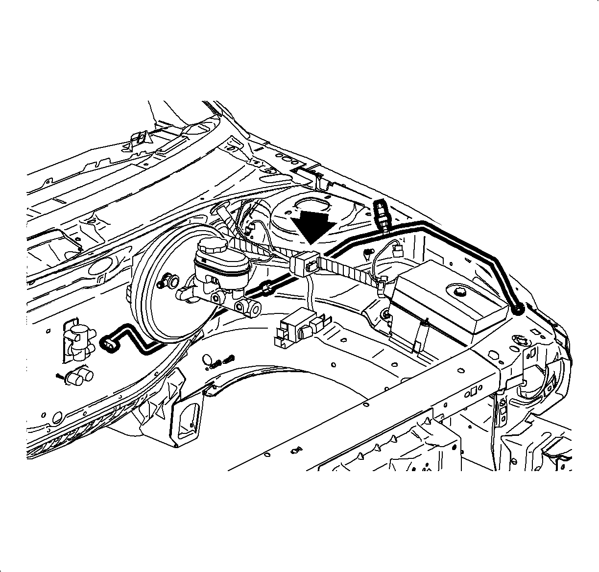
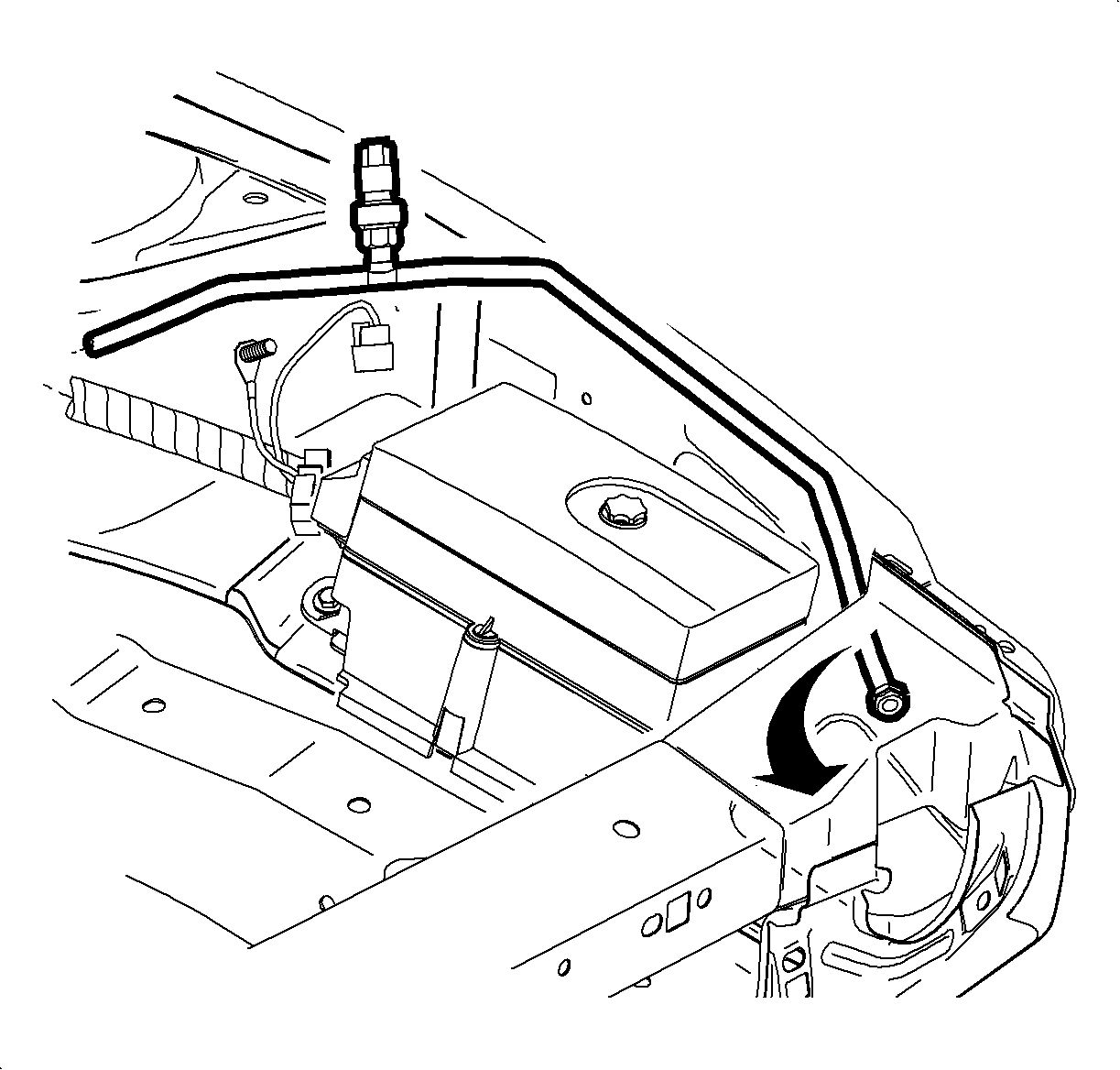
Important: Do not bend the line around the hood support rod. After lowering the rod, gently flex the line around the radiator core support.
Important: Install the liquid line in the front clamp located just behind the pressure switch.
Notice: Use only Polyalkylene Glycol Synthetic Refrigerant Oil (PAG) for internal circulation through the R-134a A/C system and only 525 viscosity mineral oil on fitting threads and O-rings. If lubricants other than those specified are used, compressor failure and/or fitting seizure may result.
Tighten
Tighten the liquid line-to-thermal expansion valve to 25 N·m (10 lb in).
Caution: Refer to Vehicle Lifting Caution in the Preface section.

Notice: Use only Polyalkylene Glycol Synthetic Refrigerant Oil (PAG) for internal circulation through the R-134a A/C system and only 525 viscosity mineral oil on fitting threads and O-rings. If lubricants other than those specified are used, compressor failure and/or fitting seizure may result.
Tighten
Tighten the liquid line-to-receiver dehydrator to 14 N·m (10 lb ft).


Tighten
Tighten the battery hold down nut to 9 N·m (80 lb in).

Tighten
Tighten the positive battery cable to 17 N·m (13 lb ft).
Tighten
Tighten the positive battery cable to 17 N·m (13 lb ft).
