Tire-Wheel-Hub Related
A vibration that is tire or wheel induced can be caused by two factors: imbalance
or runout.
Low-speed vibrations, those less than 64 km/h (40 mph), are usually runout
related. Highway speed vibrations, those above 96 km/h (60 mph), can be caused by
either imbalance or runout.
Prior to performing any work, always road test the vehicle and perform a careful
visual inspection for:
| • | Obvious tire and wheel runout. |
| • | Obvious drive axle runout. |
| • | Proper tire inflation pressure. |
| • | Debris build-up on tire or wheel. |
| • | Loose or missing wheel weights or wheel nuts. |
| • | Irregular or excessive tire wear. |
| • | Proper tire bead seating on rim. |

| • | Damaged tires, such as tread distortions, separations,
or bulges from impact damage. Slight sidewall indentations are normal and will not
affect ride quality. |

Balance is the easiest procedure to perform and should, therefore, be done first
if the vibration occurs at highway speeds. An off-car, two-plane dynamic balance should
first be performed. This will correct any imbalance in the tire and wheel assembly.
An on-car finish balance should then be performed to correct any brake drum,
rotor, or wheel cover imbalance. Follow the balancing procedures of the balancing
machine being used.
If balance does not correct the highway speed vibration, or if the vibration
is at low speeds, runout is the probable cause. Runout can be caused by the tire,
wheel, or the way the wheel attaches to the vehicle. The following procedure should
be used.
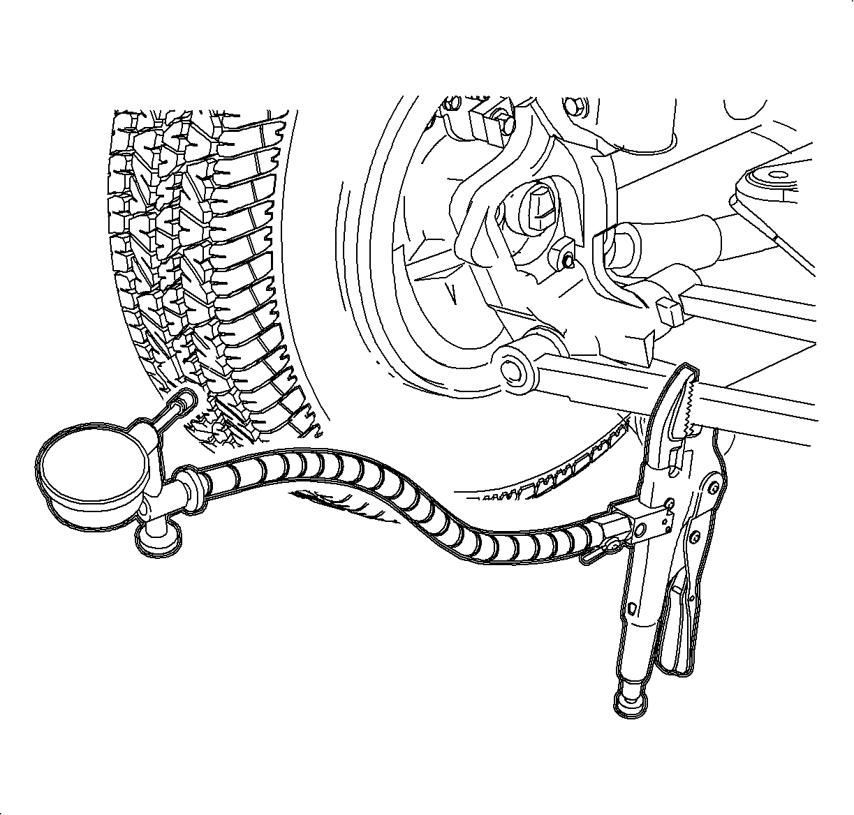
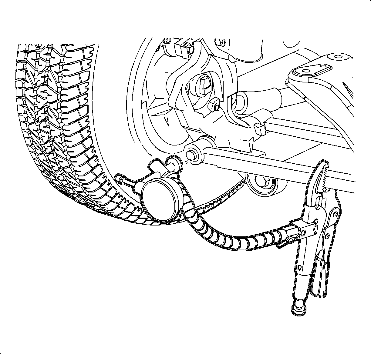
- If runout is suspected, the free runout of the tire and wheel assembly
should first be measured on the vehicle. A dial indicator with a roller wheel is preferred,
but a dial indicator with button end may be used. Lateral runout (side-to-side) should
be measured on the tire's sidewall as close to the tread shoulder as possible. Radial
runout (up and down) should be measured on the center tread rib. Some tread designs
may require tightly wrapping a piece of tape around the center tread circumference
for better dial indicator contact; for measuring wheel runout follow the procedures
in this section. Whether measuring radial or lateral runout, disregard any instantaneous
indicator needle jumps due to sidewall depressions, tread blocks, etc. Record the
total indicator reading, and the location of the high point of runout. The total tire
and wheel on-car runout should be less than 1.52 mm (0.060 in.), if either measurement
exceeds 1.52 mm (0.060 in.), proceed to step B.
- If the on-car radial or lateral runout measured in Step A exceeds 1.52
mm (0.060 in.), mount the tire and wheel assembly on a dynamic balance machine and
again measure the amount of runout. Position on machine using the wheel's inside center
pilot hole. Using same procedure in step A, record the amount of tire and wheel runout
and its high point location. Next, measure wheel (refer to procedures in this section).
If wheel exceeds specifications, replace the wheel. If tire and wheel radial or lateral
runout exceeds 1.27 mm (0.050 in.) at the tire tread, proceed to step C.
- If the off-car tire and wheel radial or lateral runout measured in step
B exceeds 1.27 mm (0.050 in.), match mount the high radial runout point of tire
to low radial runout point of wheel. Inflate, mount on the dynamic balance machine,
and again measure and record the radial and lateral runout and its location, as done
in step B. In many cases, match mounting the tire on the wheel will bring the assembly's
runout into the acceptable range of less than 1.27 mm (0.050 in.).
- If the runout of the tire and wheel assembly is within limits when measured
off the vehicle, yet exceeds the limits when measured on the vehicle, the attachment
of the tire and wheel assembly to the hub is the probable cause. Mark wheel relation
to wheel stud. Remove wheel and tire assembly and rotate 90 degrees (1/4 turn)
to next position and install. Check runout. Repeat this procedure to find best mounting
location.
- If the on-car radial or lateral runout still exceeds 1.52 mm (0.060 in.),
check hub runout. Remove the necessary rotor or drum. Make sure all hub surfaces are
free of rust, dirt, or any debris that could distort readings. Measure radial runout
at the wheel pilot. Measure lateral runout at the hub's mating surface with the wheel.
If radial runout exceeds 0.125 mm (0.005 in.) front or rear, replace hub. If lateral
runout exceeds .040 mm (0.0016 in.) on the front, replace hub. If lateral runout exceeds
0.050 mm (0.0020 in.) on the rear, replace hub.
Whenever a tire is rotated on the wheel, or whenever a tire or wheel is
replaced, the assembly must be balanced.
The substitution method of vibration diagnosis can also be used. Install a known
good set of tire and wheel assemblies. If these tires and wheel assemblies correct
the vibration, the original assemblies should be installed one at a time until the
vibration returns. This will pinpoint the bad tire/wheel assembly.
Incorrect Tire Inflation Pressure
Incorrect tire inflation pressure can lead to the following symptoms:
Over-inflation
| • | Tire bruising or carcass damage. |
| • | Rapid tread wear at center of tire. |
Under-inflation
| • | Rapid tread wear on tire edges. |
| • | Tire bruises or bead rupture. |
| • | High tire temperatures. |
Unequal-inflation pressure on same axle
| • | Swerve on acceleration. |


