Removal Procedure
- Raise vehicle squarely on a lift. Refer to lift instructions for positioning vehicle.
- Loosen front exhaust pipe clamp at engine block bracket and slide clamp out of engagement with bracket.
- Remove front exhaust pipe-to-exhaust manifold nuts, lower front exhaust pipe, remove gasket and discard.
- Lower vehicle.
- Remove the A/C compressor and the rear compressor bracket. Refer to "Engine Drive Belt and Accessories" section of this manual for A/C compressor removal procedures.
- Disconnect oxygen sensor 1 harness connector.
- Remove exhaust manifold attachment nuts.
- Remove the exhaust manifold and gasket. Discard the gasket.
- Inspect the exhaust manifold to front exhaust pipe flange for warpage. Refer to "SOHC or DOHC Cylinder Head" sections for specifications on exhaust manifold flange warpage.

Caution: Ensure that the vehicle is properly supported and squarely positioned. To help avoid personal injury when a vehicle is on a hoist, provide additional support for the vehicle on the opposite end from which the components are being removed.
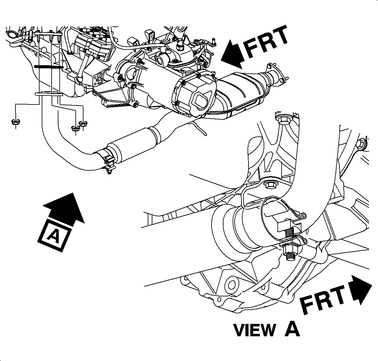
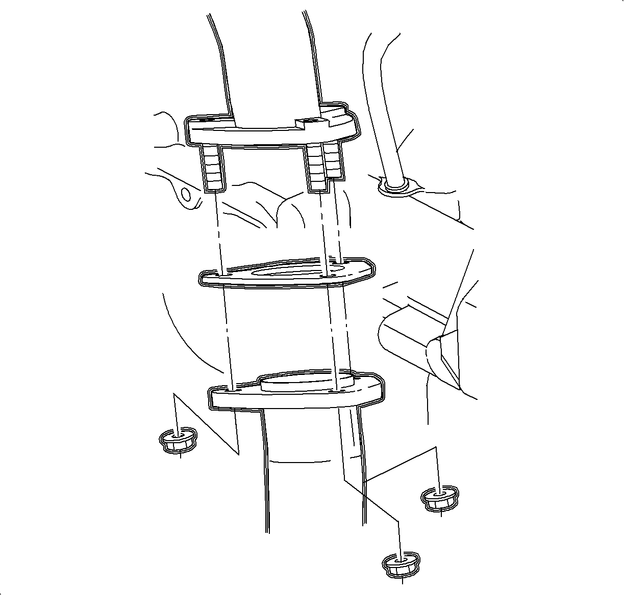
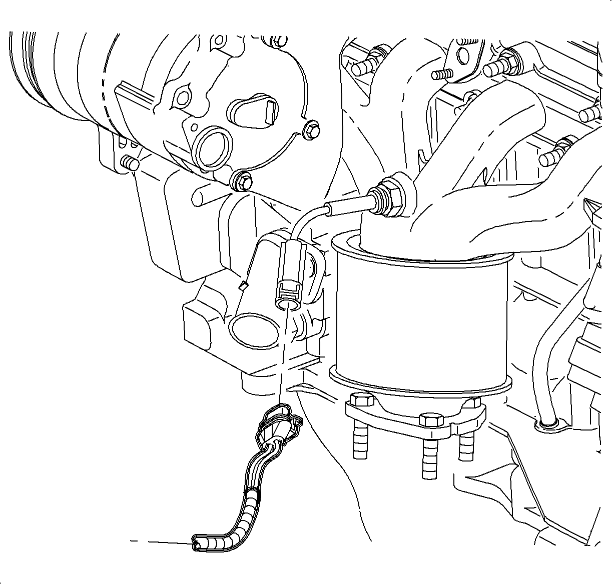
Front Exhaust Pipe-to-Manifold Flange Warpage:
Standard: 0.7 mm (0.028 in) max.
Service Limit: 0.7 mm (0.028 in) max.
Installation Procedure
- Install new exhaust manifold gasket with smooth side toward the exhaust manifold.
- Install the exhaust manifold and attachment nuts.
- In sequence, torque the exhaust manifold attachment nuts. The center fasteners may lose torque when the outer fasteners are tightened. Therefore, re-torque all fasteners a second time.
- Connect oxygen sensor 1 harness connector. Push in until a click is heard and pull back to ensure a positive engagement.
- Install A/C compressor rear bracket and A/C compressor. Refer to "Engine Drive Belt and Accessories Drive" section of this manual for A/C compressor installation.
- Raise vehicle squarely on a lift. Refer to lift instructions for positioning vehicle.
- Install new exhaust pipe-to-manifold gasket on the studs.
- Install and torque the exhaust pipe-to-manifold attachment nuts.
- Slide front exhaust pipe clamp over engine block bracket and tighten clamp.
- Lower vehicle and check for leaks.
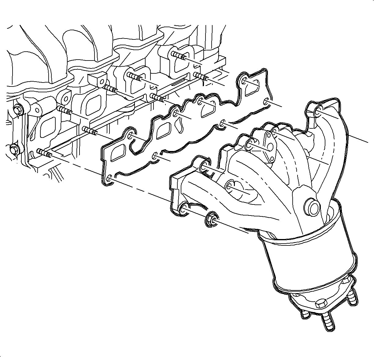
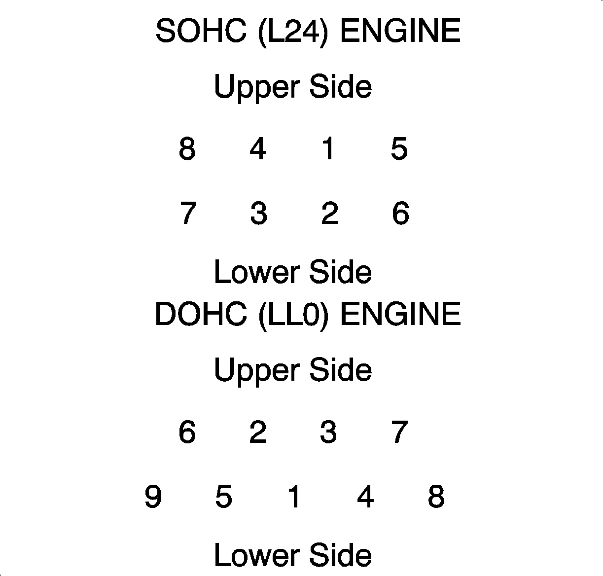
Tighten
Tighten Exhaust Manifold-to-Head (L24) 22 N·m (16 lbs ft).
Tighten
Tighten Exhaust Manifold-to-Head (LL0) 17 N·m (13 lbs ft).
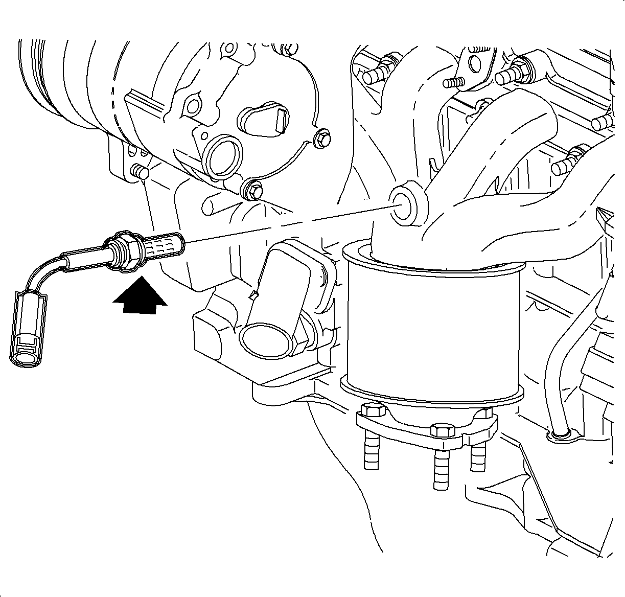
Important: Whenever the oxygen sensor 1 is removed, coat the threads with a nickel based anti-seize such as Saturn P/N 21485279 (or equivalent). If oxygen sensor 1 is replaced, do not apply anti-seize to the new sensor. New sensors have anti-seize pre-applied. Do not use an anti-seize that contains silicone.
Tighten
Tighten Sensor - Oxygen-to-Exhaust Manifold 45 N·m (33 lbs ft).
Tighten
Tighten Front/Rear Brackets-to-Head/Block 25 N·m (19 lbs ft).
Tighten
Tighten Compressor-to-Front Bracket 54 N·m (40 lbs ft).
Tighten
Tighten Compressor-to-Rear Bracket 25 N·m (19 lbs ft).

Tighten
Tighten Exhaust Pipe-to-Manifold 31 N·m (23 lbs ft).

Tighten
Tighten Exhaust Pipe Clamp-to-Support Bracket 60 N·m (44 lbs ft).
