Tools Required
J 43914 Universal Clamp Pliers
Removal Procedure
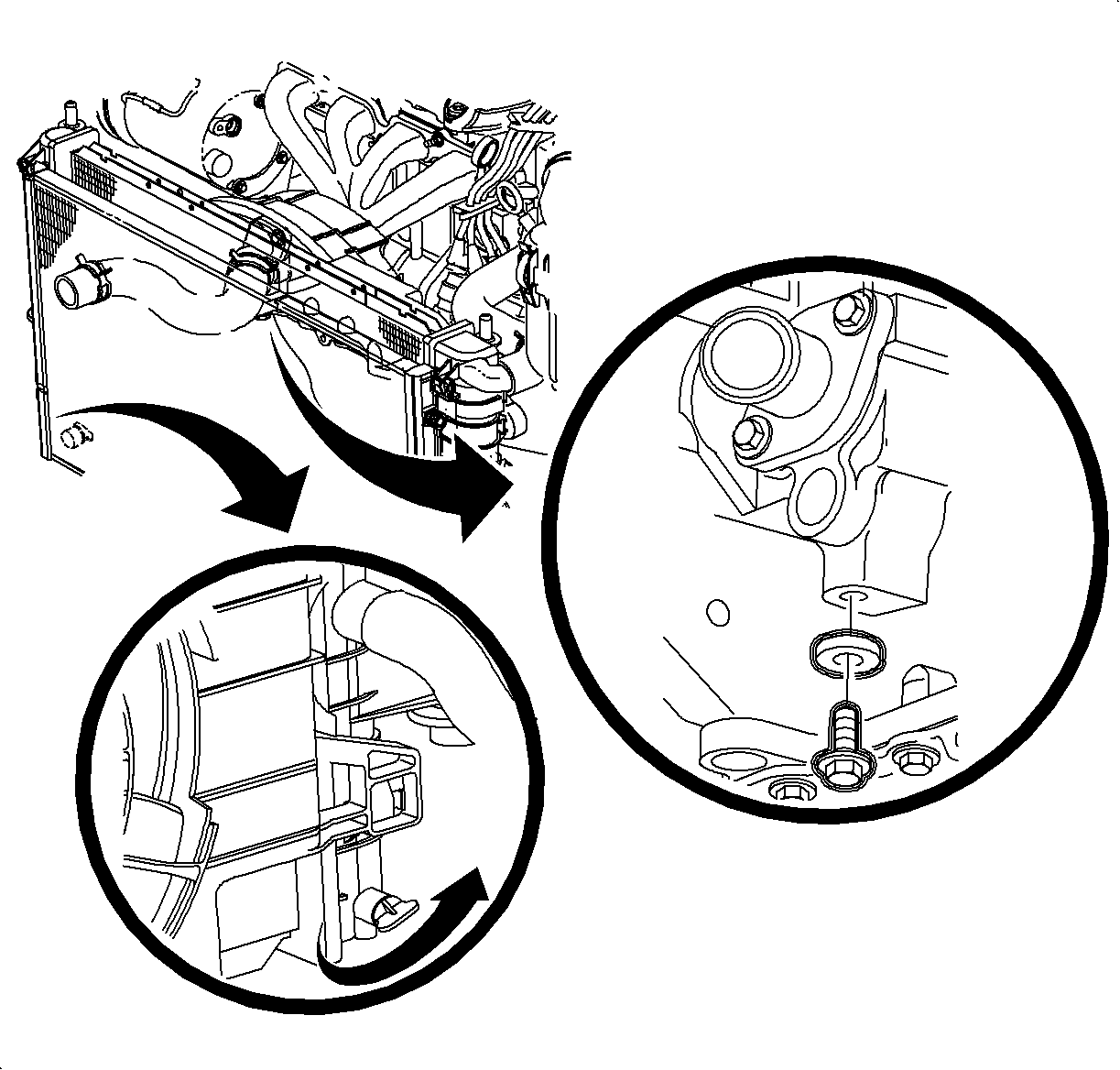
- Drain the coolant from the radiator and engine drain plug located at the right front of the engine.
- Disconnect the lower radiator hose at the thermostat housing. Use the J 43914 or equivalent.
- Remove the two bolts in the water inlet housing.
- Remove the water inlet housing and thermostat assembly.
- Remove the O-ring.
- Remove the thermostat element using the service tool provided with the replacement element.
- Inspect the thermostat components for damage, seat deterioration, etc.
Important: During extremely cold weather, -12°C (+10°F) or colder, the engine's coolant temperatue will decrease quickly when idling with the heater fan on high speed, and cool air may flow from the heater outlet.
The fan control switch should be set at a slower speed position (fan speed I or II) to maintain the hottest air flow.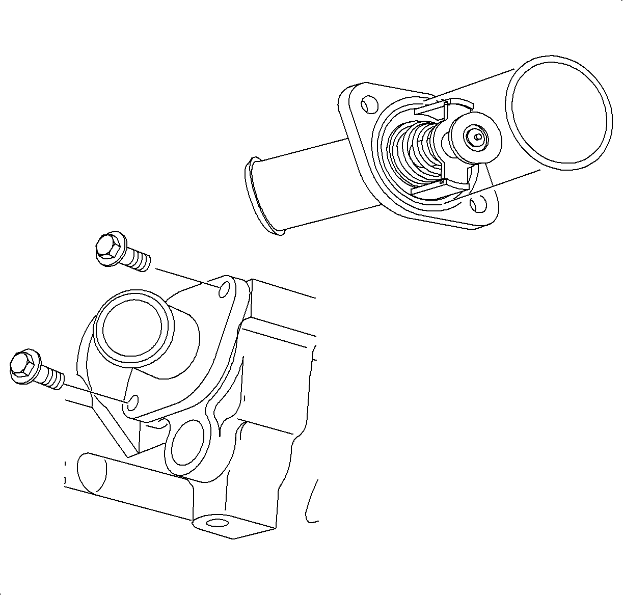
Important: The O-ring gasket must be replaced whenever the thermostat housing is removed.
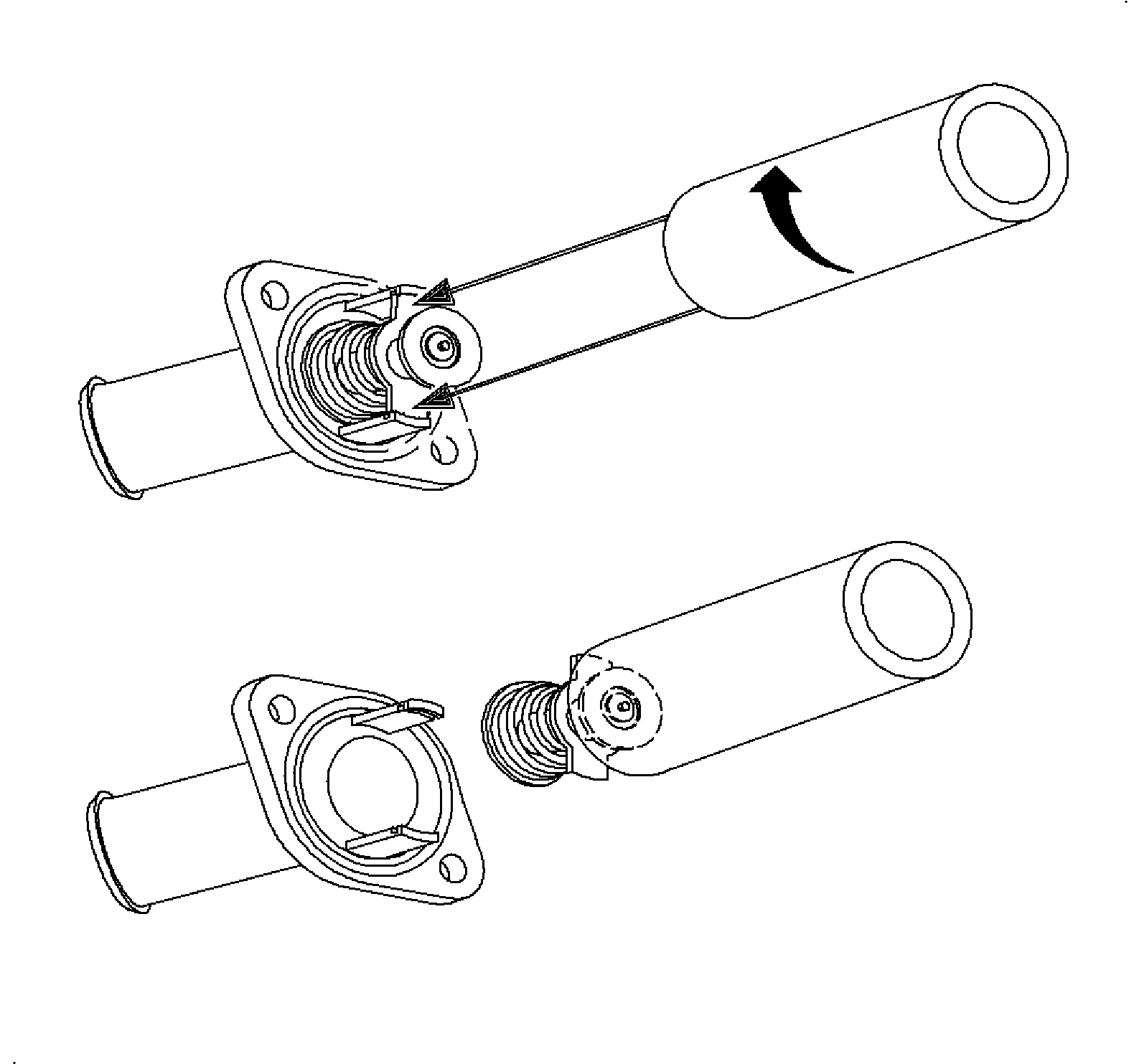
Important: The thermostat element should not be removed if the assembly requires testing.
Notice: The thermostat will not function correctly once it is contacted by oil. If oil is found in the cooling system, it must be flushed and the thermostat's cartridge replaced.
Thermostat Inspection
- Check the valve opening temperature.
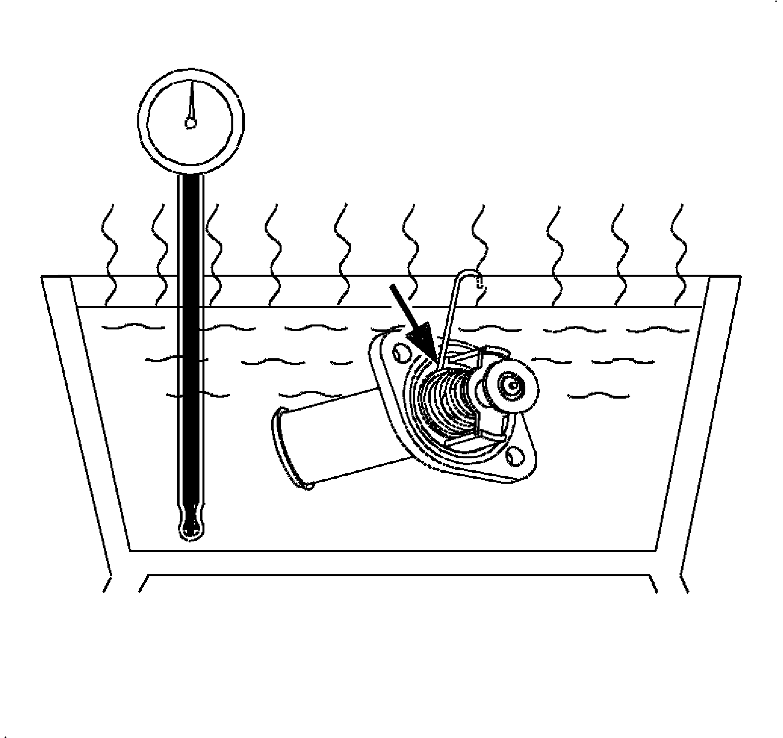
- Insert a small paper clip or tag wire between the main poppet valve seat and housing.
- Suspend the thermostat from the paper clip in a pan of water and gradually heat the water.
- Check the water temperature immediately after the thermostat falls off a tag wire or small paper clip.
- Replace the thermostat if it does not fall within specifications.
- Check the full valve opening temperature.
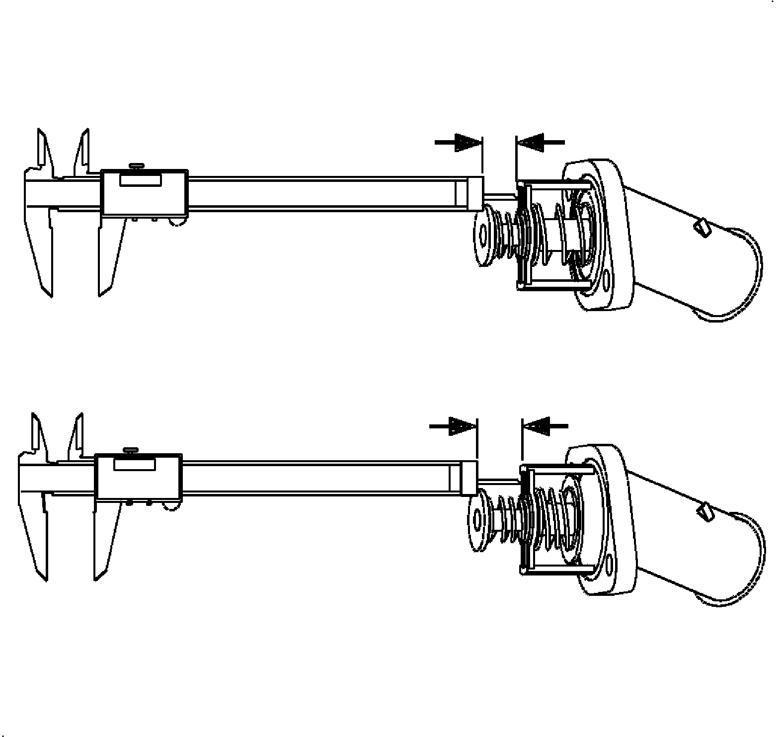
- Use a pair of calipers and check the distance between the thermostat bypass valve and the frame when the thermostat is cold.
- Heat the thermostat in water until the main poppet valve fully opens.
- Measure the distance between the frame and bypass valve.
- Subtract the valve open reading from the close position measurement.
- Check the water temperatures and measurements to make sure the thermostat is opening at the proper temperatures and to the correct lift.
- If the valve opening temperature is not within the specification, replace the thermostat.
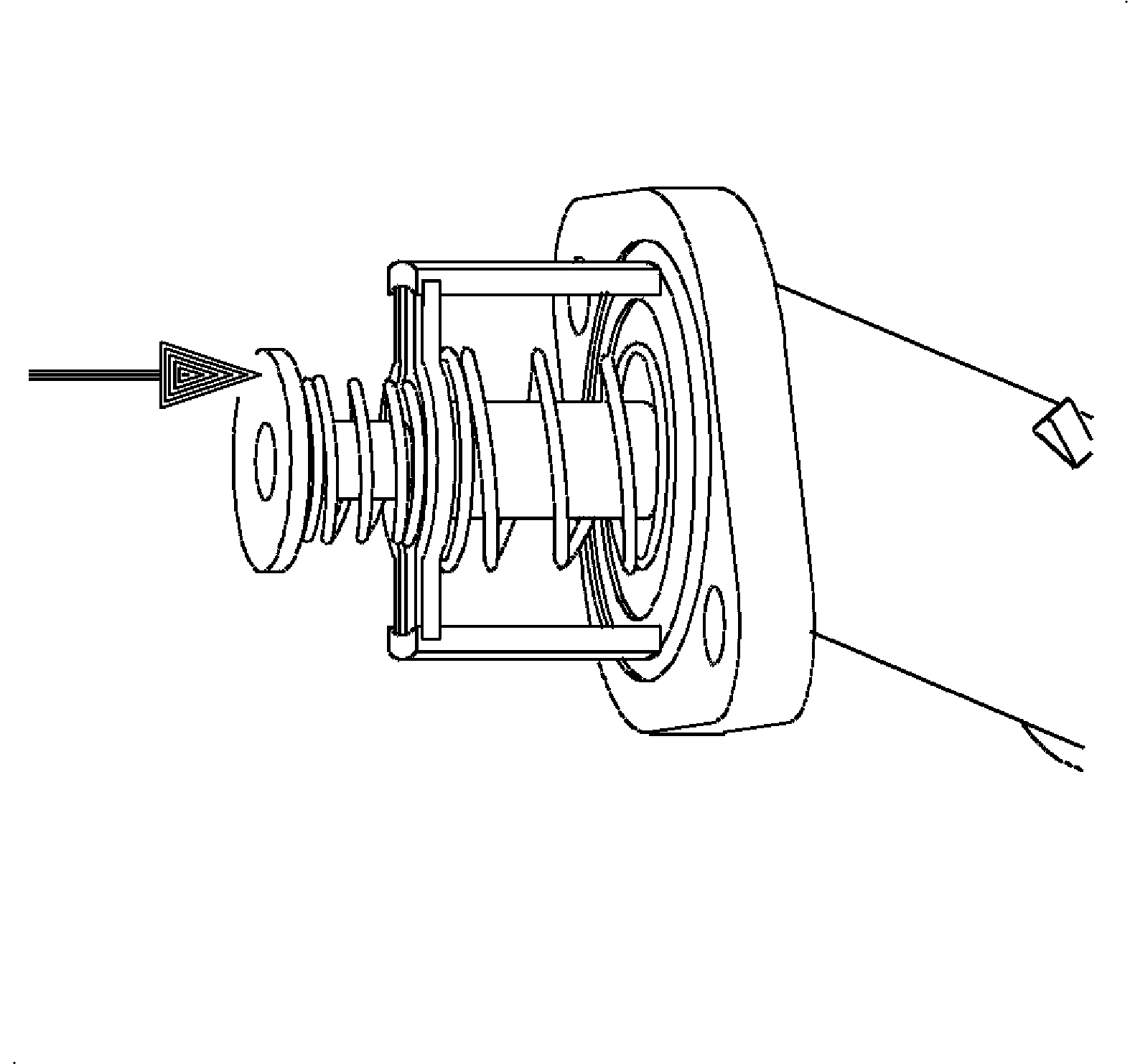
- Check the valve lift.
- If the valve full opening temperature or lift are not within the specifications, replace the thermostat.
- Check that the main poppet and bypass valve springs are tight when the thermostat is fully closed. If necessary, replace the thermostat assembly.
- Check the main poppet rubber seat. If the rubber is deteriorated, replace the thermostat cartridge.
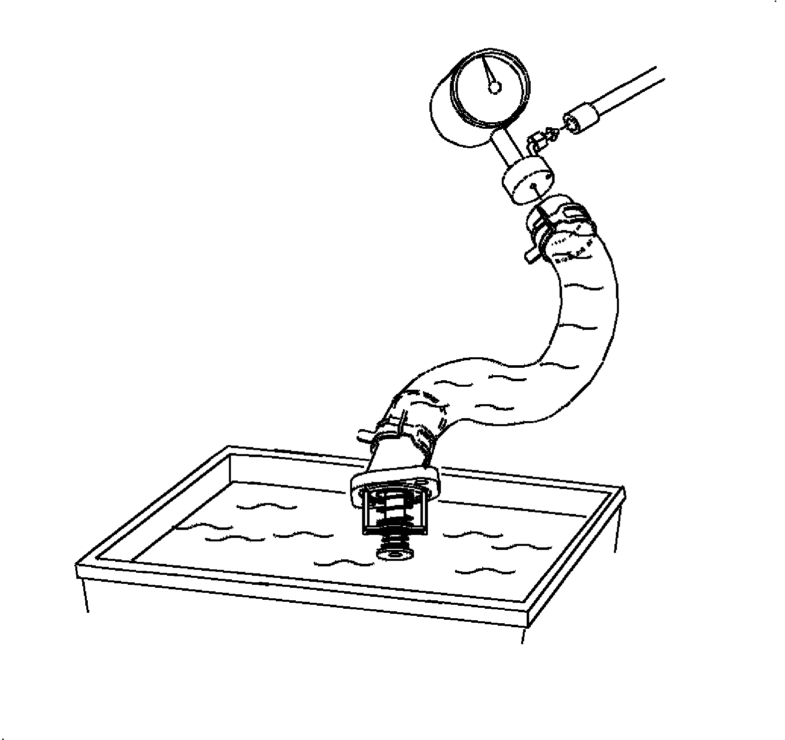
- Check the thermostat for leakage around the main poppet and check the valves.
- Install the lower radiator hose on the thermostat housing assembly and fill the hose with clean water.
- Install a plug with an adapter in the other end of the hose.
- Place the thermostat in a two quart container and apply five 35.5 kPa (5 psi) of shop air pressure.
- Measure the amount of leakage from the assembly for 5 minutes.
- If the leakage exceeds the specifications, replace the thermostat assembly.
Notice: Use extreme care and do not damage or scratch the machined aluminum surfaces. Leaks will result.
Specifications
| • | New - valve opening temperature: 84-88°C (182-190°F) |
| • | Used - valve opening temperature: 83-89°C (180-192°F) |
Specifications
| • | New - valve opening temperature: 100°C (212°F) |
| • | Used - valve opening temperature: 105°C (222°F) |
Specifications
| • | New - minimum valve lift: 7.5 mm (0.295 in) |
| • | Used - minimum valve lift: 6 mm (0.236 in) |
Specifications
| • | New - maximum leakage after 5 minutes: 0.89 L (1.68 pts.) |
| • | Used - maximum leakage after 5 minutes: 0.95 L (2 pts.) |
Installation Procedure
- Replace the thermostat element using the service tool provided.
- Install a new O-ring on the inlet housing:
- Install the lower radiator hose.
- Fill the cooling system to the FULL COLD range with coolant. Use a 50/50 mixture of Dex-Cool™ antifreeze and clean water.
- Run the engine until the upper radiator hose is hot, then add additional coolant, if needed, to bring the level to the FULL COLD range.
- Install the coolant surge tank cap and check for leaks.
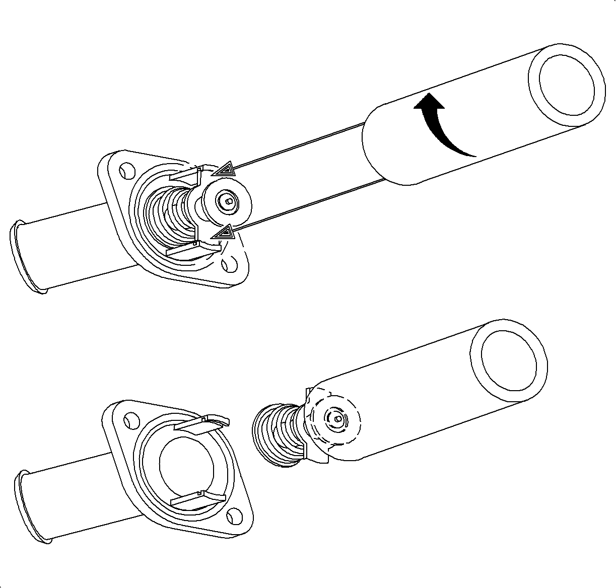
Important: Make sure the element's retaining tangs are properly seated in the two legs and the element piston is correctly positioned in the water inlet housing.

| 2.1. | Install the thermostat and inlet housing into the cylinder block. |
Notice: Refer to Fastener Notice in the Preface section.
| 2.2. | Install the retaining bolts. |
Tighten
Tighten the thermostat housing-to-block to 30 N·m (22 lb ft).
| 2.3. | Close the radiator drain plug and install the cylinder block drain plug. |
Tighten
Tighten the cylinder block drain plugs to 35 N·m (26 lb ft).
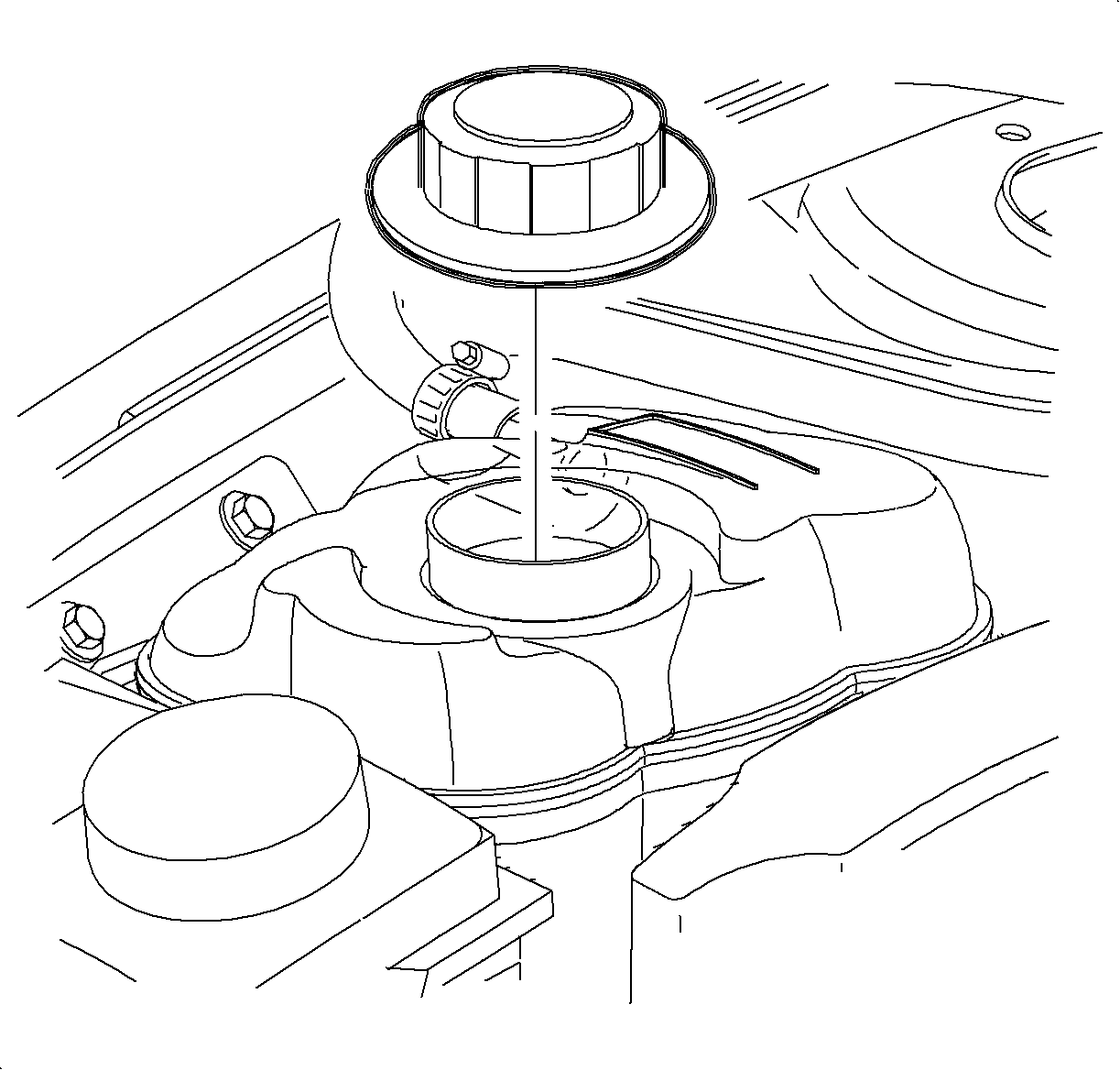
Important: The vehicle must be level when filling with coolant.
