Removal Procedure
- Raise the vehicle.
- Drain the cooling system. Refer to Engine Coolant Check and Replacement .
- Remove the right front tire and wheel assembly.
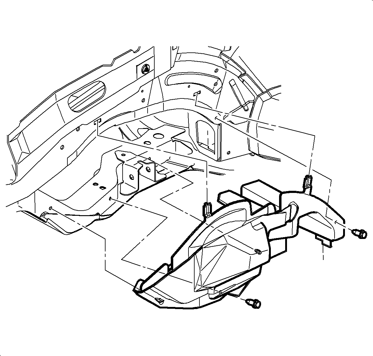
- Remove the right upper wheelhouse panel.
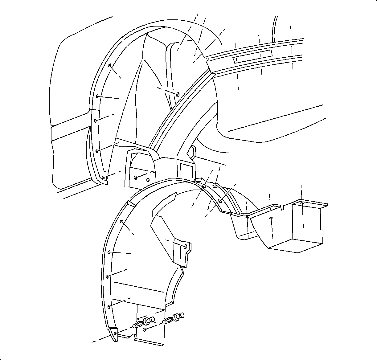
- Remove the right wheelhouse side splash shield (left hand shown).
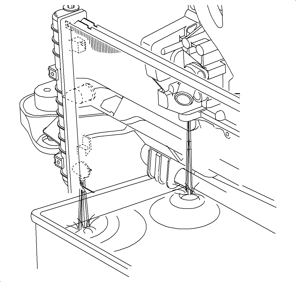
- Place a 25 mm x 25 mm x 51 mm (1 in x 1 in x 2 in) long block of wood (1) between the torque strut and cradle.
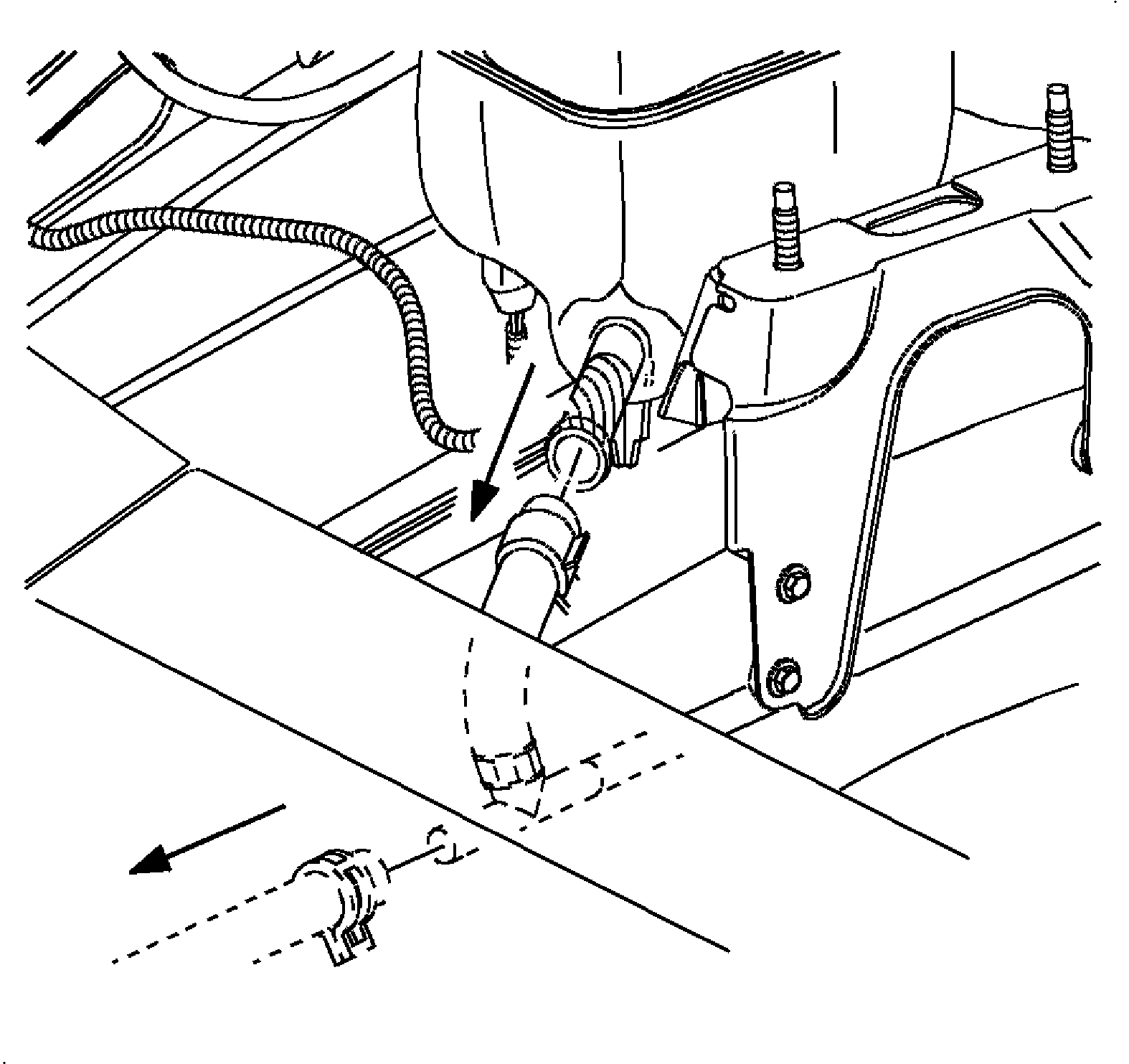
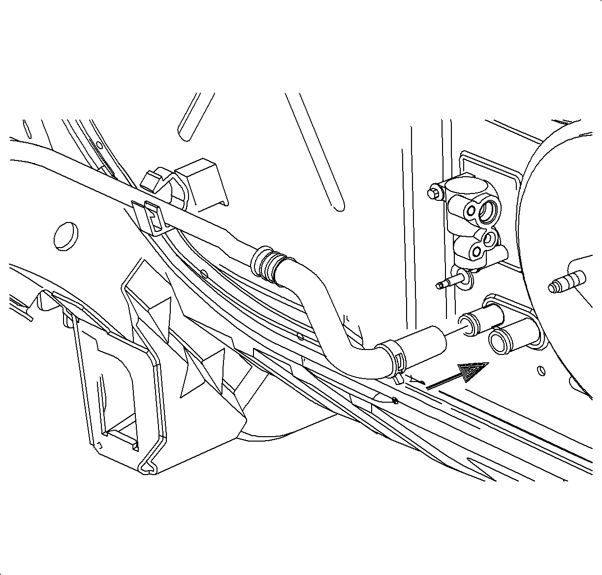
- Move the heater outlet clamp and hose from the heater core outlet pipe.
- Lower the vehicle.
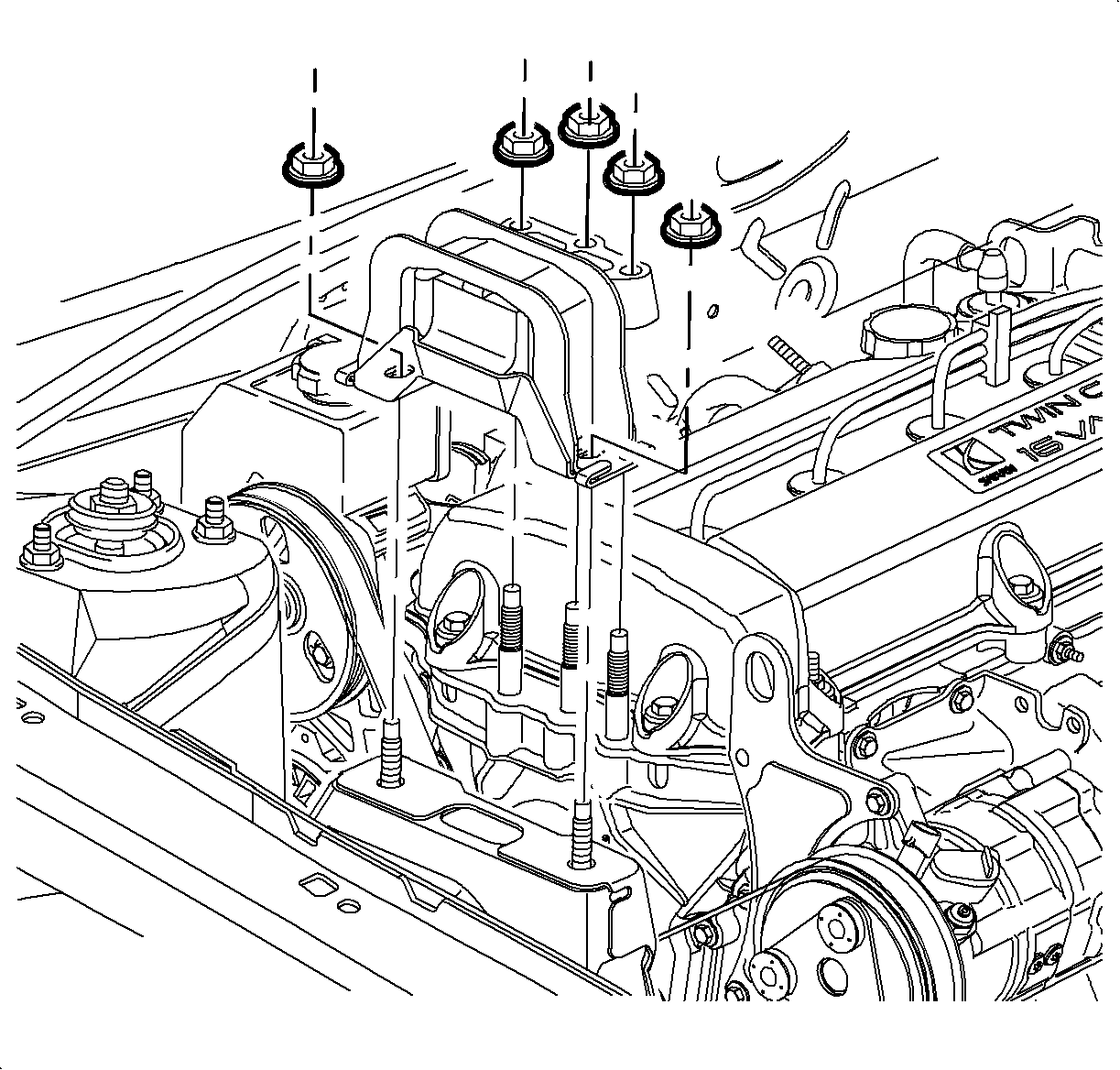
- Remove the three engine mount to front cover nuts and two engine mount to midrail bracket nuts. Allow the powertrain to rest on the block of wood.
- Remove the mount.
- Raise the vehicle.
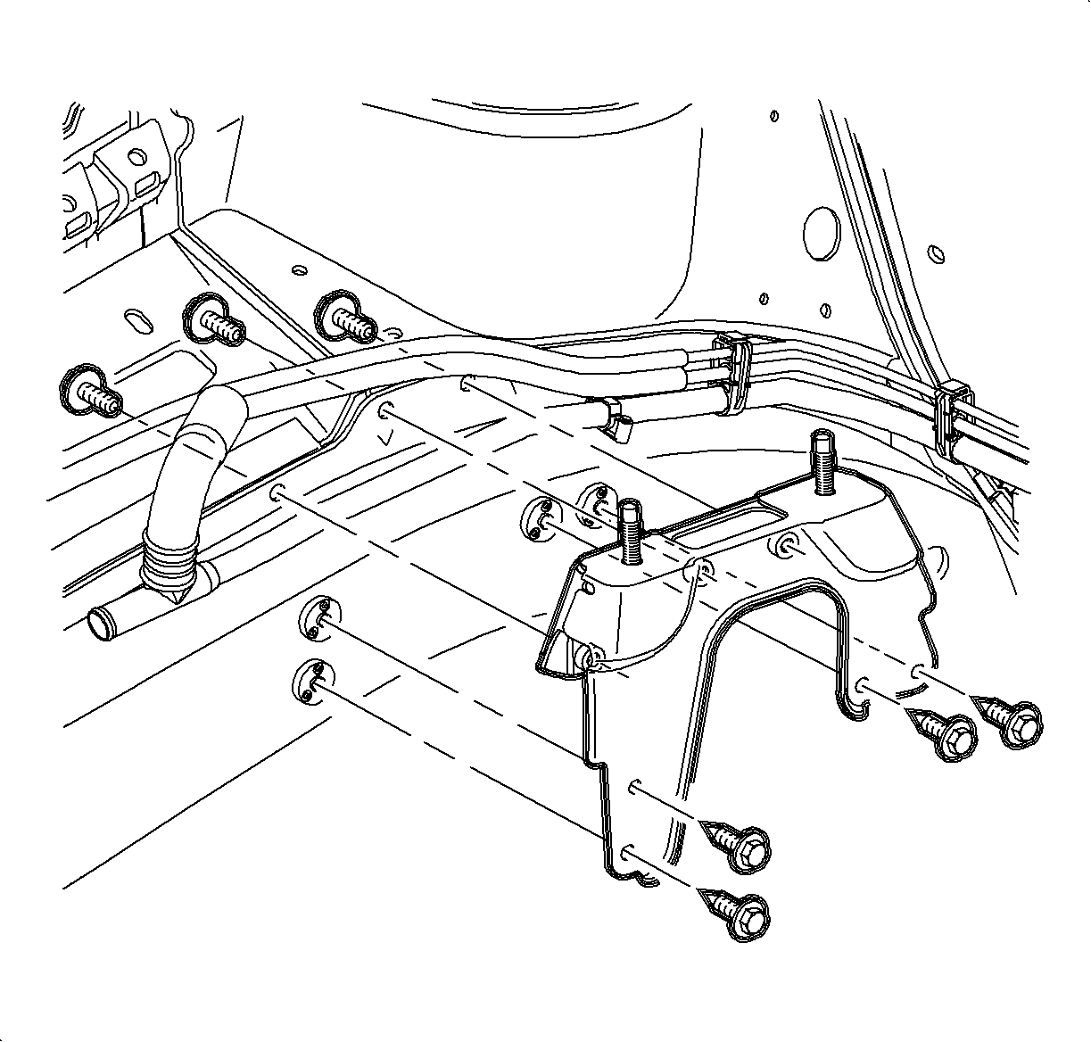
- Remove the four bracket to midrail bolts from the engine side of the bracket and the three bracket to midrail bolts from the wheelhouse side of the bracket.
- Remove the bracket.
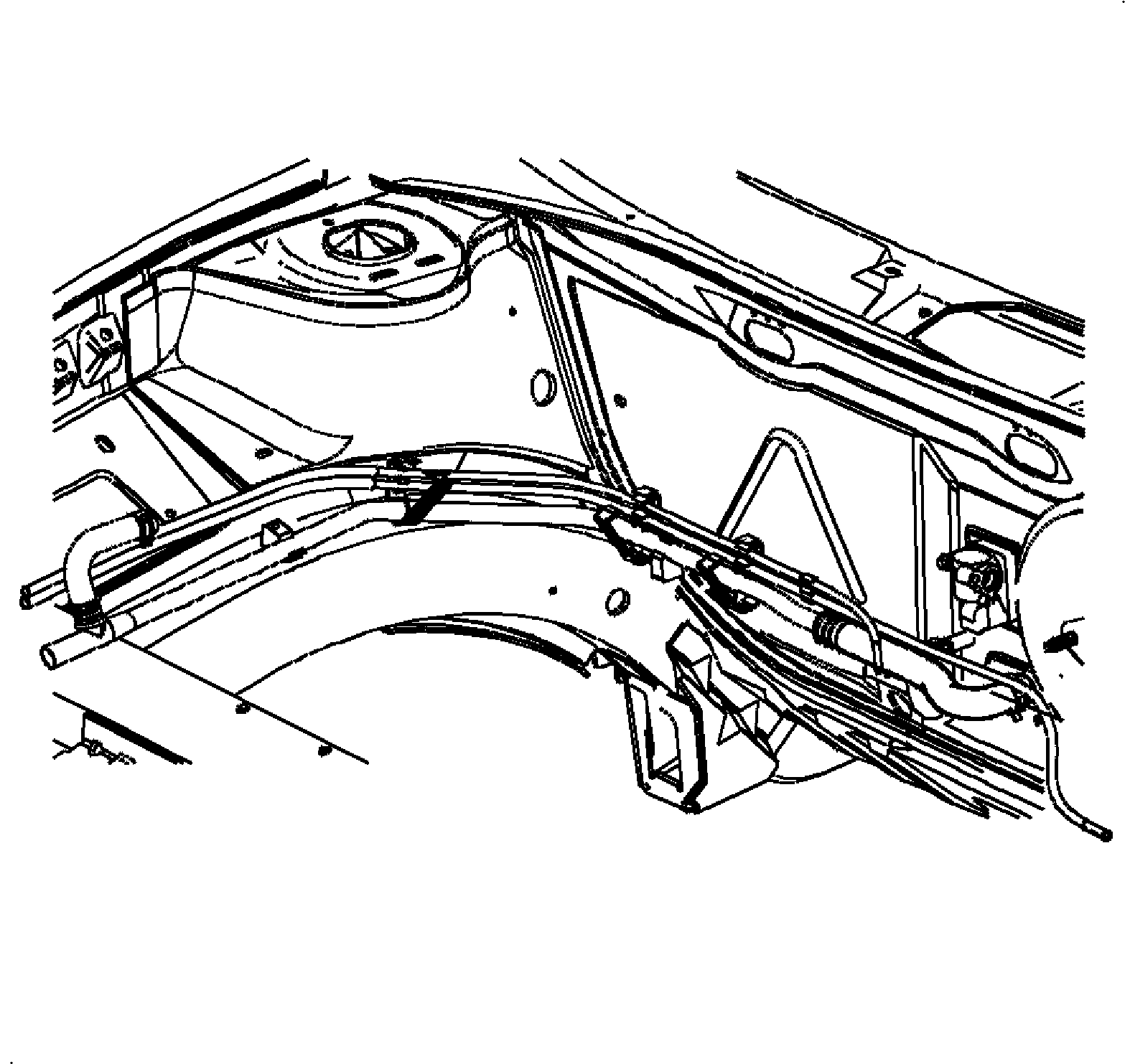
- Open the fuel vapor line clamps holding the heater return line.
- Remove the fuel vapor line clip from the stud.
- Lower the vehicle.
- Remove the remaining clamp and clip from the midrail.
- Remove the washer bottle bolt and move the washer bottle aside.
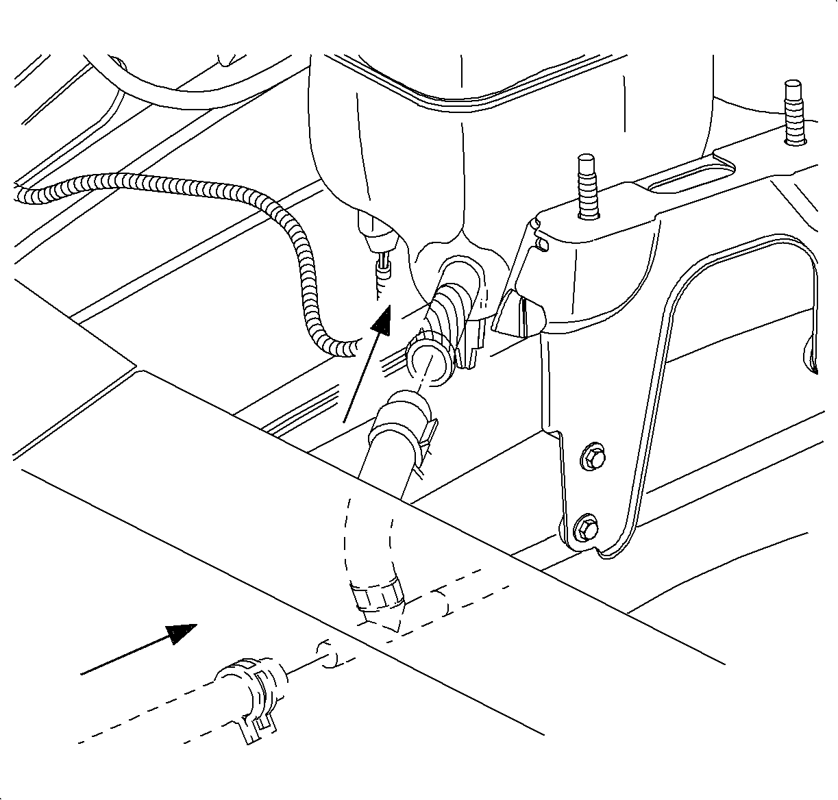
- Remove the hoses from the coolant surge tank and the heater return pipe.
- Remove the heater return pipe from the vehicle.
Caution: Ensure that the vehicle is properly supported and squarely positioned. To help avoid personal injury when a vehicle is on a hoist, provide additional support for the vehicle on the opposite end from which the components are being removed.
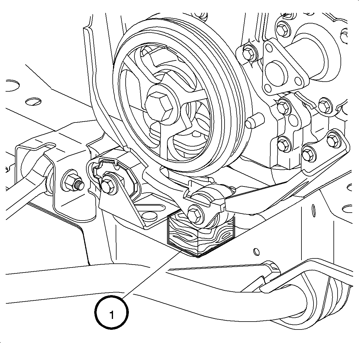
Important: Installation of the wood block prior to the upper engine torque axis mount removal allows the mount to be easily installed without lifting or jacking the powertrain.
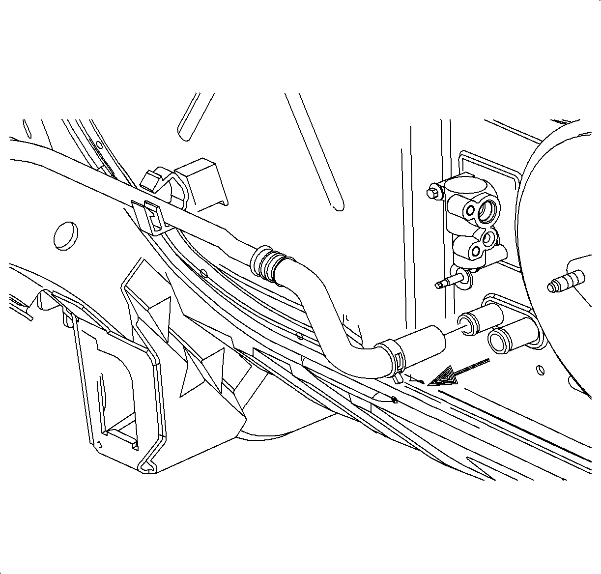
Caution: To prevent personal injury, do not stand under a heater core outlet when removing the hose because some coolant will leak out after the hose is removed.
Installation Procedure
- Transfer the hose clamp to the new return pipe.
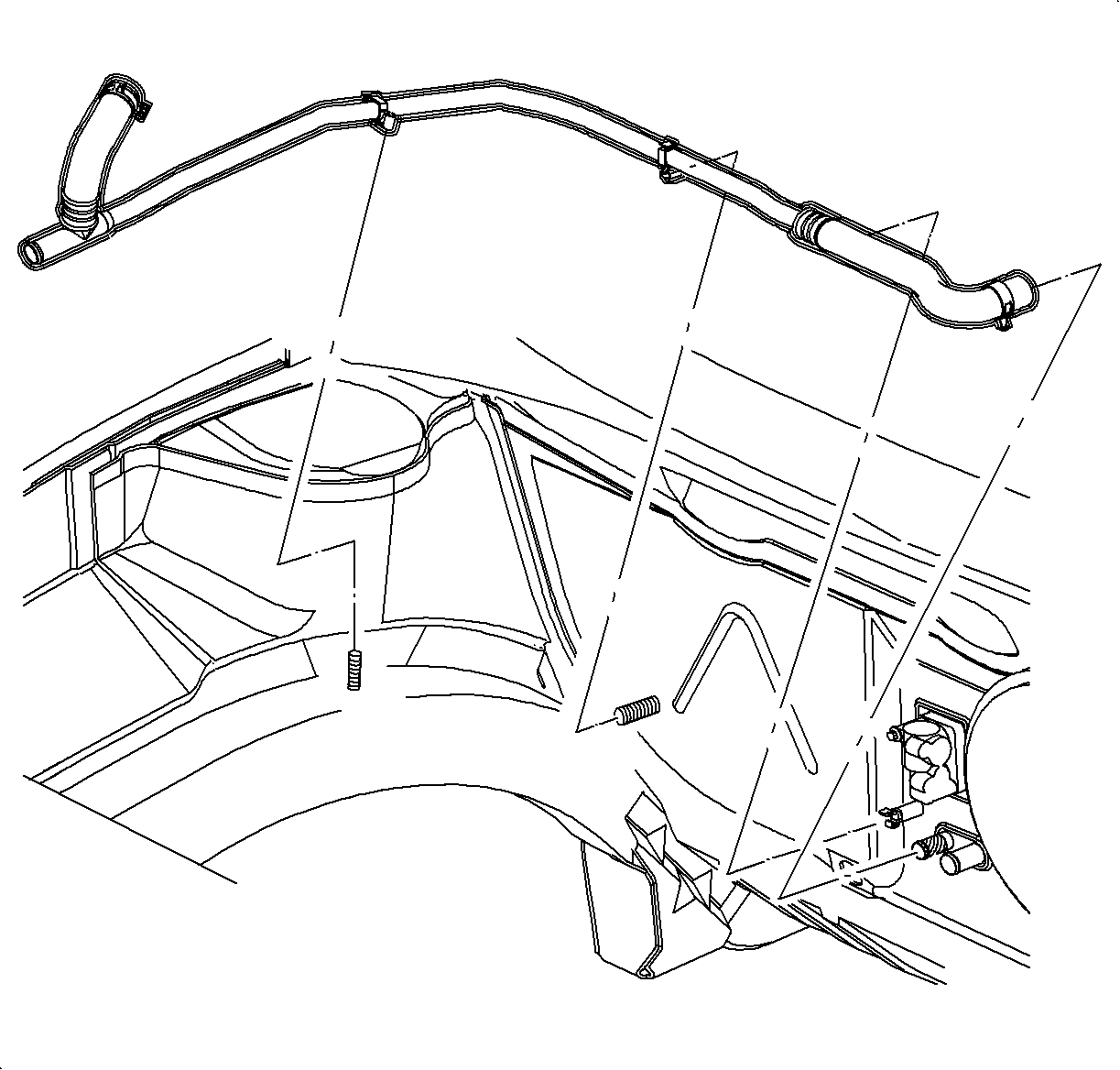
- Install the heater return pipe behind the engine and into position at the coolant recovery reservoir.
- Raise the vehicle.
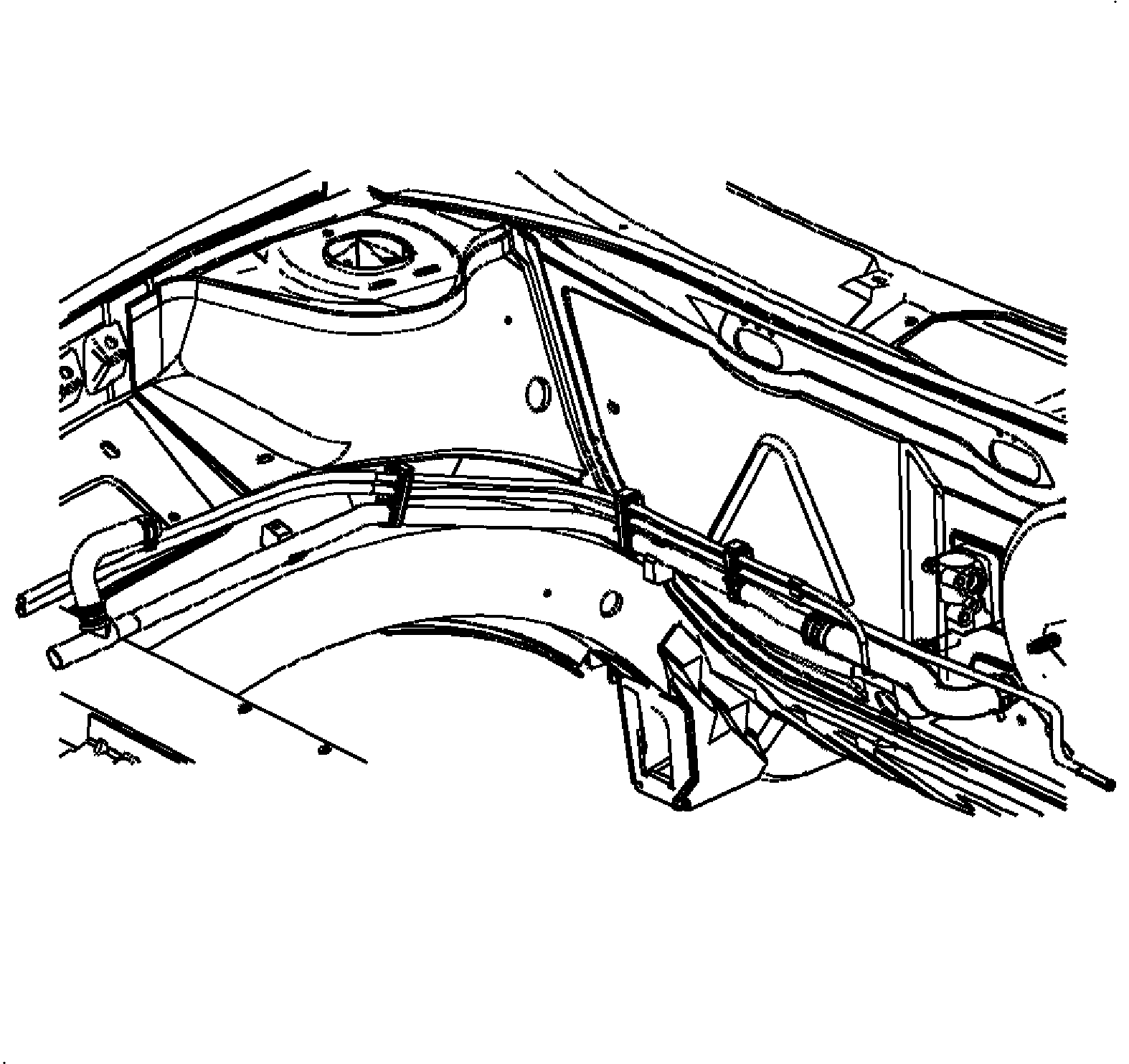
- Position the pipe in front of the dash clamps and clips on the studs. Close all clamps.
- Install the hose to the heater core outlet. Position the clamp at 6 o'clock.
- Lower the vehicle.
- Position the pipe in the mid-rail clamp and close.
- Install the hoses and clamps to the bottle and pipe. Position the clamps at 3 o'clock.
- Install the washer bottle and bolt.
- Install the midrail bracket.
- Raise the vehicle.
- Hand start all the midrail bracket bolts.
- Tighten and torque all of the bolts.
- Lower the vehicle.
- Install the two engine mount to the midrail bracket nuts first.
- Install the three engine mount to the engine front cover nuts.
- Remove the block of wood from under the torque strut after the upper mount assembly is installed.
- Raise the vehicle.
- Install the upper wheelhouse panel.
- Install the wheelhouse side splash shield (left hand shown).
- Install the tire and wheel assembly.
- Close the radiator drain valve and install the engine block drain.
- Lower the vehicle.
- Fill the cooling system and leak check. Refer to Engine Coolant Check and Replacement .
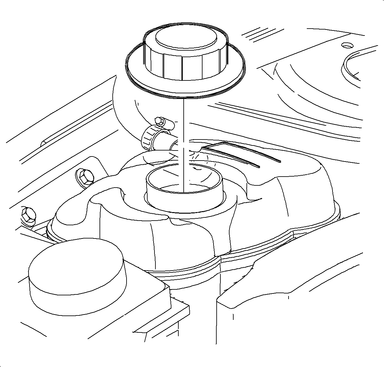
- Install and tighten the coolant surge tank cap.
Notice: Refer to Fastener Notice in the Preface section.
Tighten
Tighten the washer bottle attachment bolts to 4 N·m (35 lb in).

Tighten
Tighten the midrail bracket bolts to 30 N·m (22 lb ft).

Notice: To prevent engine front cover and mount damage, the three engine mount to engine front cover nuts must be tightened down uniformly.
Tighten
| • | Tighten the engine mount to front cover nuts to 50 N·m (37 lb ft). |
| • | Tighten the engine mount to midrail bracket nuts to 50 N·m (37 lb ft). |


Tighten
Tighten the wheel nuts to 140 N·m (103 lb ft).
