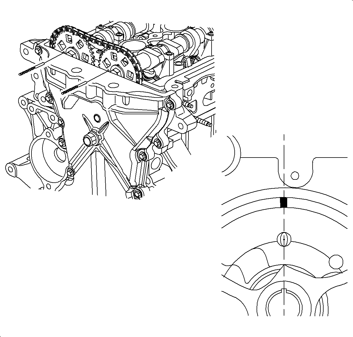
- Remove gasket material.
Using a gasket scraper, Scotch Brite® Pads and Disk 3M® Clean' N Strip
2 inch D x 1/2 inch W x 1/4 inch
center hole remove all the gasket material from the cylinder block, oil pan, rear
seal carrier, and front cover surfaces.
- The oil pan, front cover, and rear seal carrier bolt holes in cylinder
block will require cleaning with a 4.76 mm (3/16 in) drill and tap
handle to remove RTV.
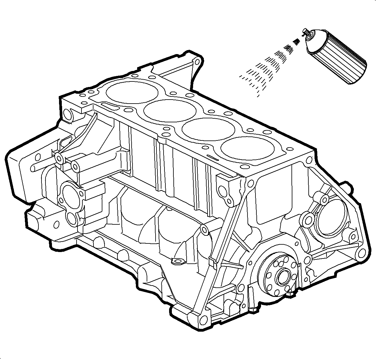
Important: If excessive RTV, wet or dry accumulates in blind holes, the casting will crack
when bolts are installed.
- When all RTV is removed, clean the surfaces with a chlorinated solvent,
such as carburetor spray cleaner, brake clean, or alcohol Saturn P/N 21007432
or equivalent.
Important: Do not use petroleum cleaners such as mineral spirts; they leave a film onto
which RTV will not stick.
- If cylinder block oil gallery plugs are removed, clean the threads and apply
Saturn P/N 21485276, Loctite 290® (or equivalent).
Tighten
Tighten the oil gallery plug-to-block to 30 N·m (22 lb ft).
Notice: Use extreme care and do not damage or scratch the machined aluminum surfaces
and the cylinder bores. Do not heat the cylinder block above 44°C (120°F).
- Clean cylinder block:
Using a soft scrub brush and solvent, clean the entire block of oil, debris,
etc.
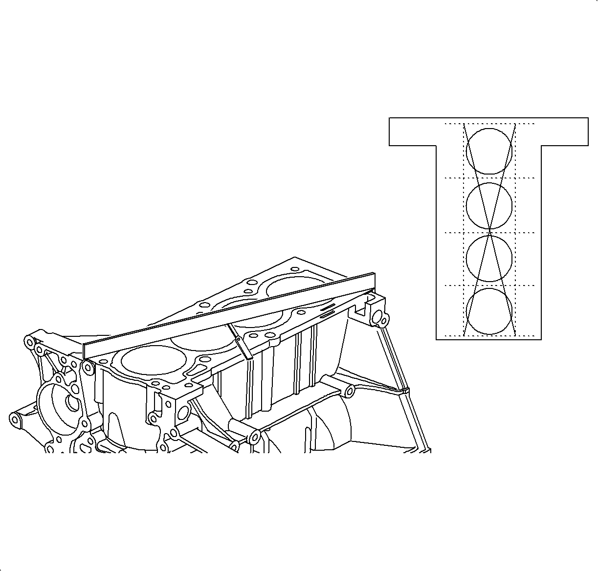
- Inspect top of cylinder block for flatness.
Using a SA9177NE
or equivalent
and a SA91101NE
or equivalent,
measure the surfaces contacting the cylinder head gasket for warpage.
Transverse Warpage
| • | Standard: 0.024 mm (0.0009 in) max. |
| • | Service Limit: 0.05 mm (0.002 in) max. |
Longitudinal Warpage
| • | Standard: 0.08 mm (0.0031 in) max. |
| • | Service Limit: 0.1 mm (0.004 in) max. |
| • | If warpage is greater than maximum, replace the cylinder block. |
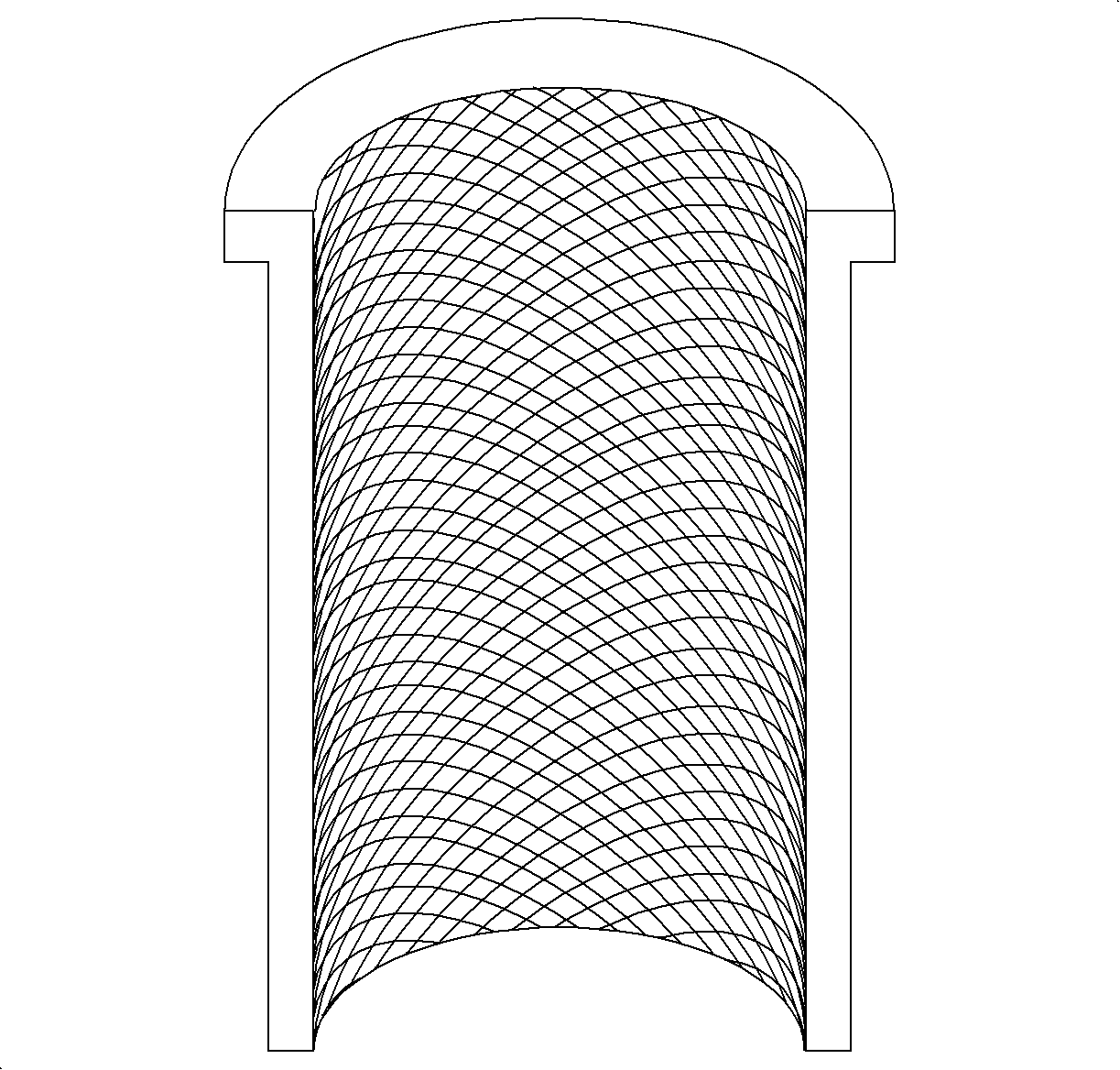
- Inspect cylinders for scoring or vertical scratches.
If deep scratches are present, hone or bore the worn or scored cylinders. Refer
to Cylinder Honing and Boring in this section.
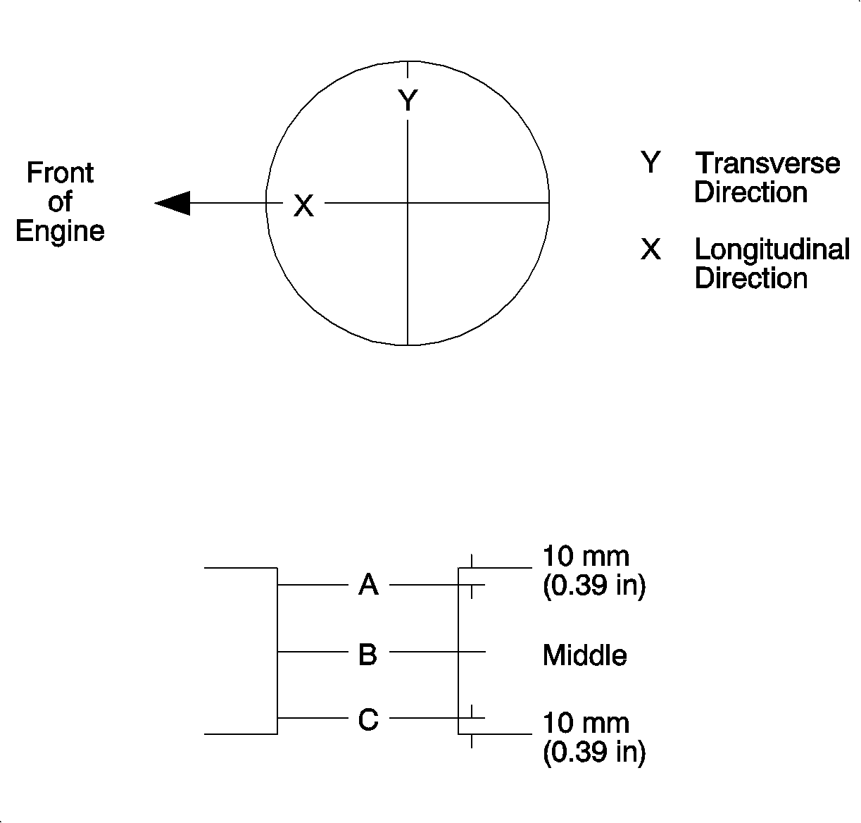
- Inspect cylinder bore diameter:
Using a cylinder bore gage, measure the cylinder bore diameter at positions
A, B, and C in the transverse and longitudinal directions. Record these dimensions.
Calculate the average diameter at each position (A, B, and C). The
average value is the dimension to be compared to specifications.
Cylinder Bore Diameter No. 2 and 3
| • | Standard: 81.99-82.01 mm (3.228-3.2287 in) |
| • | Service Limit: 82.035 mm (3.2297 in) max. |
| • | (average X and Y direction measurements) |
Cylinder Bore Diameter No. 1 and 4
| • | Standard: 82-82.02 mm (3.2283-3.2291 in) |
| • | Service Limit: 82.045 mm (3.2301 in) max. |
| • | (average X and Y direction measurements) |
Cylinder Bore Taper
| • | Standard: 0.01 mm (0.0004 in) max. |
| • | Service Limit: 0.05 mm (0.002 in) max. |
| • | (average X and Y direction measurements) |
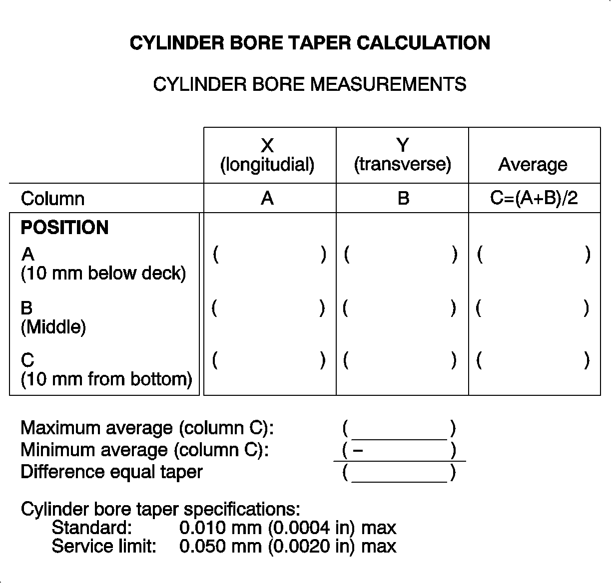
- Use the cylinder bore taper calculation chart to calculate bore taper.
If the diameter is greater than maximum, hone, or re-bore the worn or scored
cylinders. If necessary, replace the cylinder block.
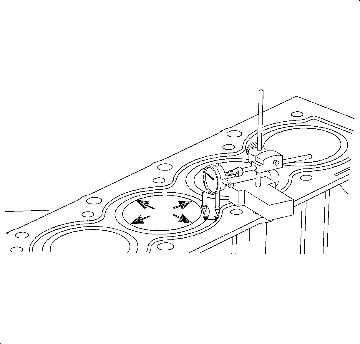
- Using a SA9179NE
, or equivalent,
or straight edge and feeler gage, measure the cylinder liner height at position
A, B, C, and D at the top of the cylinder block.
Liner Height Above or Below Cylinder Block
| • | Service Limit: 0.013 mm (0.0005 in) max. |
| • | If the liner height is below the cylinder block, the cylinder block may require
surfacing or replacement. |
Top side of main bearing bore to cylinder head deck surface
Service Limit: 189.26 mm (7.4511 in).
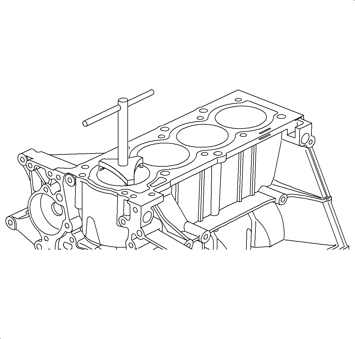
Important: Failure to removed ridge can cause upper piston ring damage when new rings are
installed.
- Remove the J 24270
or equivalent
if not previously completed during piston removal.
If a ridge can be felt in the cylinder bore above the upper ring, use a ridge
reamer to machine the piston ring ridge at the top of the cylinder.


