Tools Required
J 43223 Rocker Arm Removal Tool
Removal Procedure

- Remove the spark plug wires, accessory drive belt, fresh air hose, and cam cover
assembly. Disconnect fuel injector electrical connectors if removing intake rocker
arm assemblies or intake lash adjusters.
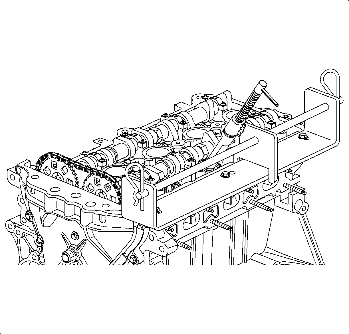
- Install theJ 43223
to the
cylinder head rail. The tool consists of the following components:
| • | Sliding Bracket J43223-3 |

Important: Position the crankshaft and camshafts as described in the following steps to
prevent valves from contacting pistons. If the valves contact the pistons, the valve
stem keys may become dislodged from the valve stem retaining groove. This could result
in significant engine damage.
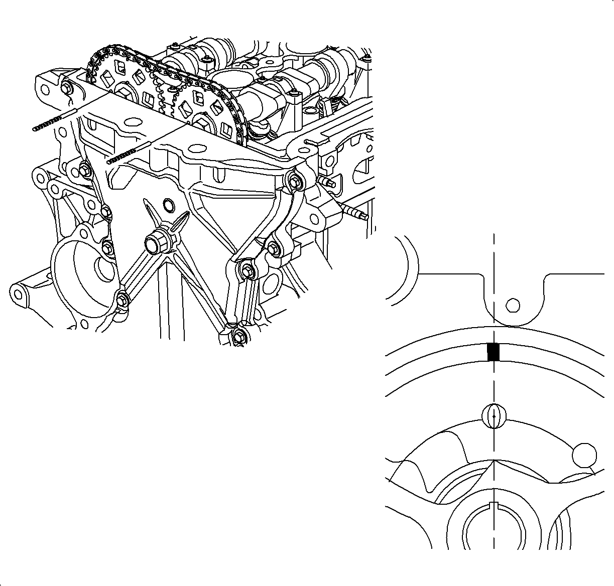
- Position the crankshaft at TDC with the pip marks on the camshaft sprockets
at the 12 o'clock position. Next, rotate the crankshaft 90 degrees
past TDC. With the crankshaft at this position, the following rocker arm assemblies
and lash adjusters can be removed.
| • | #1 Intake -- #1 Exhaust |
| • | #2 Intake -- #3 Exhaust |

- To remove the remaining rocker arm assemblies or lash adjusters, rotate the
crankshaft an additional 360 degrees. The following rocker arm assemblies
and lash adjusters can be removed.
| • | #2 Exhaust -- #3 Intake |
| • | #4 Intake -- #4 Exhaust |
- Position compressor over valve spring and compress valve spring by rotating
screw.
- With magnet or fingers, remove rocker arm assemblies and/or hydraulic
lash adjusters.
Installation Procedure

- With rocker arm removal tools assembled to cylinder head rail and valve spring
compressed, install hydraulic lash adjuster and rocker arm assembly.
- Remove rocker arm removal toolJ 43223
.
- Install cam cover assembly, PVC fresh air house, accessory drive belt,
and spark plug wires.


