Removal Procedure
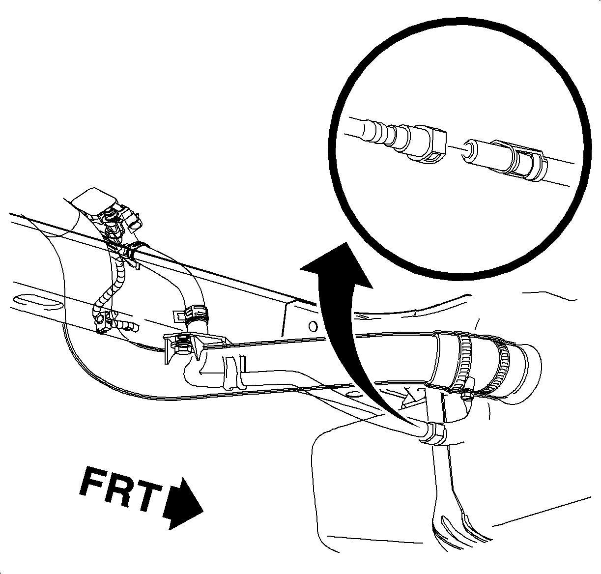
The EVAP vent solenoid is located on the upper-end of the fuel filler pipe inside the left-rear wheel opening.
- Raise the vehicle.
- Remove the left rear inner fender well.
- Disconnect the vent solenoid quick connect pipe.
- Disconnect the EVAP vent solenoid harness connector.
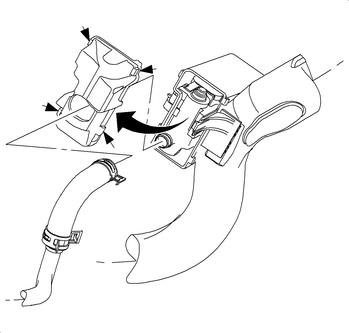
- Slide the spring clamp nearest the vent solenoid down on the molded hose.
- Disengage the 4 locking tabs from the shield of the EVAP vent solenoid box.
- Remove the shield on the EVAP vent solenoid box and slide down the molded hose.
- Remove the vent solenoid from the box and vent pipe from the vehicle.
- Disconnect the vent solenoid from the molded rubber hose.

Caution: Ensure that the vehicle is properly supported and squarely positioned. To help avoid personal injury when a vehicle is on a hoist, provide additional support for the vehicle on the opposite end from which the components are being removed.

Installation Procedure
- Install the EVAP vent solenoid to the box on the filler pipe.
- Install the shield on the EVAP vent solenoid box.
- Install the vent pipe and molded hose to the quick connect on the EVAP canister vent hose.
- Install the vent pipe hose to the EVAP vent solenoid and secure with a clamp.
- Connect the EVAP vent solenoid harness connector. Push in the connector until a click is heard and pull back to confirm a position engagement.
- Install the left rear inner fender well.
- Perform the "Service Bay Test" for the evaporative emission system using a scan tool. This test will verify the integrity of the vapor handling areas of the fuel system.

Important: Ensure that the vent solenoid "clicks" into engagement with the locking tab on the box.

Important: The lid or shield for the EVAP vent solenoid must always be installed. The lid and the solenoid box shield the vent solenoid from water and contaminants. This allows the vent solenoid to function properly.
Important: Ensure that the vent pipe is properly positioned in the retainer on the fuel filler pipe lower attachment.
