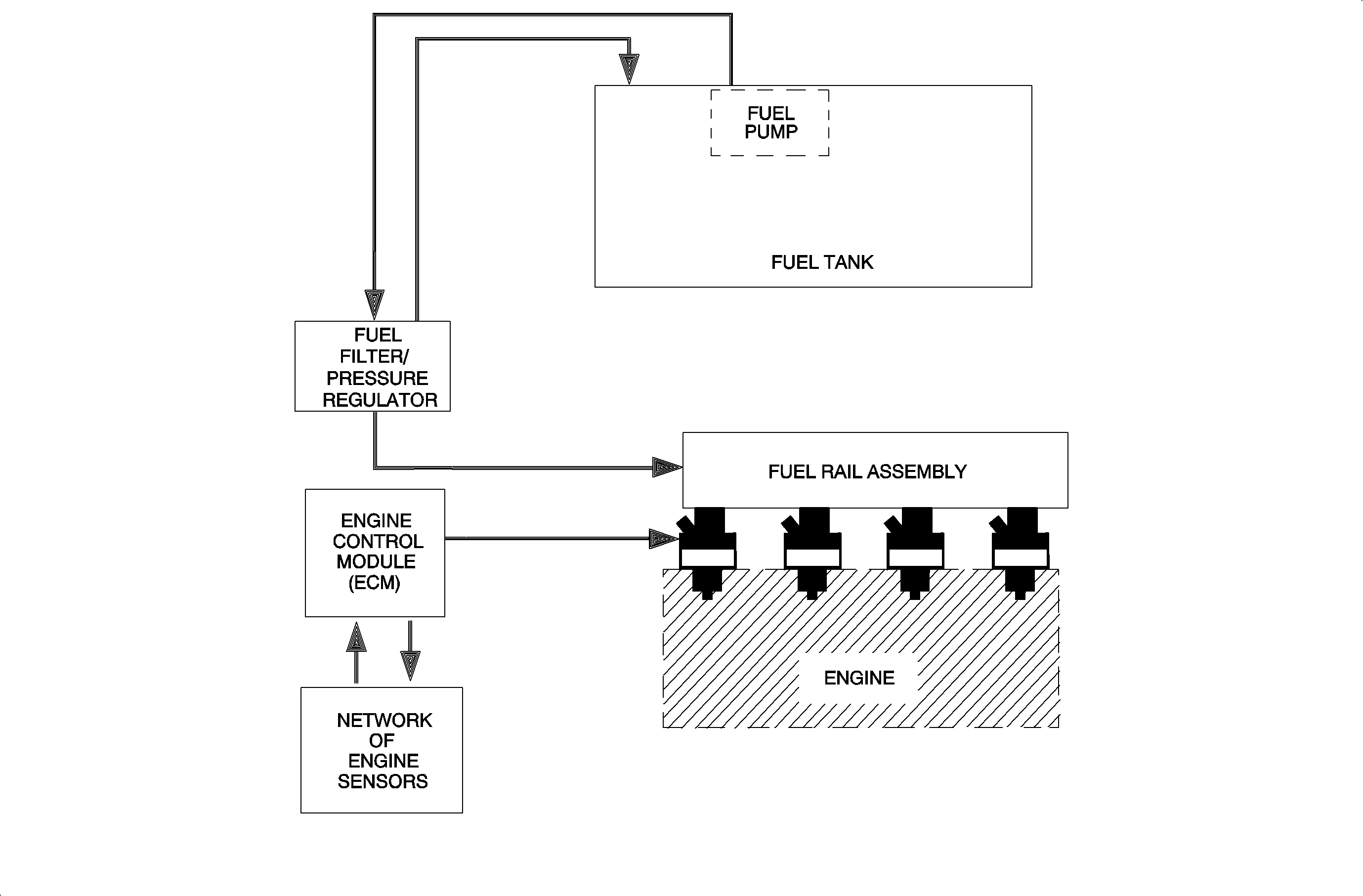
The single overhead cam (SOHC) and dual overhead cam (DOHC) engines utilize sequential fuel injection (SFI). SFI allows the PCM to individually control each fuel injector which optimizes fuel economy and performance. The PCM pulse width modulates (PWM) each fuel injector by individually pulling each fuel injector circuit to ground.
The PCM bases its fuel injector pulse width (the amount of fuel the engine needs) on three main parameters:
| • | Temperature of the air/fuel mixture at the intake valve |
| Calculation is based on the engine coolant temperature (ECT) sensor and intake air temperature (IAT) sensor. |
| • | Engine speed from the crankshaft position (CKP) sensor |
| • | Engine load |
| Calculation is based on the manifold absolute pressure (MAP) sensor and the throttle position (TP) sensor. |
| The throttle position (TP) sensor is used to ensure a correct load value if throttle change is rapid, however, the MAP sensor is primarily used. |
These parameters allow the PCM to calculate a base fuel injector pulse width when the system is in open loop. Open loop is when the PCM is not using the oxygen sensor 1 (O2S-1) to modify fuel. The system is in open loop anytime the engine is running and the O2S-1 is not varying above 600 mV or below 300 mV. The O2S-1 signal on the scan tool will read between 391-491 mV when cold.
The PCM will go into open loop fuel control if a fault exists in the O2S-1 circuit. If a fault exists in one of the sensors necessary to calculate the base pulse width, the PCM will attempt to calculate a modeled value for substitution into the calculation. However, the scan tool will still read the real sensor signal.
When the O2S-1 is above 316°C (600°F), it produces a voltage based on the amount of oxygen in the exhaust gas. The PCM can make fuel corrections to achieve a desired 14.7:1 air/fuel ratio by using the O2S-1. Normal readings vary between 10-999 mV. When the PCM detects the O2S-1 voltage above 600 mV or under 300 mV for a short period of time, it will go into Closed Loop fuel control. When the exhaust gas has high oxygen content, the air/fuel mixture is lean and the O2S-1 signal voltage will be low. To compensate, the PCM will command rich or increase the fuel injector pulse width. When the exhaust gas has low oxygen content, the air/fuel mixture is rich and the O2S-1 signal voltage will be high. To compensate, the PCM will decrease the amount of fuel by reducing the injector pulse width.
The PCM has the ability to adapt fuel control based on previous O2S-1 signals. The short term fuel trim (STFT) value is used to adapt fuel control over a short period of time. A value of 0 percent is the nominal STFT value the engine should be running at. If the engine is running at 0 percent in Closed Loop, the PCM does not have to modify fuel to obtain a 14.7:1 air/fuel ratio. If for instance the vehicle is running rich, the STFT value will decrease causing the PCM to decrease the injector pulse width. The PCM will continue to do this until the O2S-1 indicates a lean condition. The PCM will toggle from rich to lean to improve catalytic converter efficiency.
The long term fuel trim (LTFT) values are an average of the STFT values. There are 4 different LTFT cells: decel, idle, cruise and accel. When the vehicle is in one of these conditions, it will use the LTFT adaptive fuel correction value that it has stored. For instance, the vehicle could be running lean at idle, but be rich while cruising. So if the vehicle is cruising then comes down to idle, the PCM will automatically increase the injector pulse width according to the idle LTFT cell value. The PCM also uses a different set of cells when the EVAP purge solenoid is commanded ON to purge fuel vapors from the EVAP canister to the intake manifold.
To obtain a reading of how the vehicle is running overall, the LTFT values should be used. To obtain a reading of how the vehicle is running at a particular instant, the STFT value should be used. The STFT and LTFT values can significantly aid in diagnosing a driveability concern if used properly.
Misfire Diagnostics
The PCM receives A/C voltage pulses from the crankshaft position sensor to determine the position of the engine at various degrees of rotation. The PCM monitors the acceleration and deceleration rate of the crankshaft when each cylinder is in its firing event. The PCM bases misfire diagnostics on the principle that the crankshaft velocity will increase as each cylinder contributes its power input. A misfire on a cylinder occurs when the acceleration rate of the crankshaft falls below what the minimum acceleration rate should be on a normal firing cylinder.
The PCM begins monitoring the engine for misfires once misfire enable criteria, which can be found under DTC P0300, has been met. The PCM will perform 200 revolution segment tests. During this time, if any misfires are occurring, the scan tool will display the number of misfires under parameter MISFIRE CURRENT CYLS. #1-4. Once a 200 revolution test is completed, the current misfire counters will be moved to the MISFIRE HISTORY CYLS. #1-4 and the current counters will be reset to 0. The history counters will be reset to 0 when the ignition is cycled, unless DTC P0300 is active. The history counters will not be cleared until DTCs are cleared using the scan tool.
There are two types of misfires: an emission related misfire and a catalyst damaging misfire. An emission related misfire indicates that within a 200 revolution test (400 combustion events), 2-19 percent (8-76 combustion events) of the combustion events failed. If the PCM fails 10 out of 16, 200 revolution tests, DTC P0300 will set. If after the second ignition cycle, the PCM fails another 10 out of 16, 200 revolution tests, it will send a message to the I/P cluster over the Class II link to turn ON the malfunction indicator lamp (MIL).
A catalyst damaging misfire indicates that within a 200 revolution test (400 combustion events), 20 percent or greater (77 combustion events or greater) of the combustion events failed. If the PCM fails 4 out of 16, 200 revolution tests, DTC P0300 will set. The PCM will send a message to the I/P cluster over the class 2 link to flash the MIL until it no longer detects a catalyst damaging misfire.
The MIL will be turned OFF after three passed trips under the same criteria that set DTC P0300 or 80 passed trips if the criteria could not be met. DTC P0300 will be the only DTC stored in memory for a misfire condition regardless if the misfire was specific or random. The misfire history counters under MISFIRE-DATA DISPLAY will have to be reviewed as to which cylinder(s) was misfiring.
CRANKSHAFT RELEARN: In order to correctly detect misfires, the PCM must learn the variation between the 7 crankshaft notches. This procedure is performed only once. However, if the crankshaft is replaced, the crankshaft variation must be performed again. This can be accomplished using the scan tool or Service Stall System (SSS). The following is a description of what happens when this procedure is performed.When the procedure is initiated, the scan tool or SSS will send a message to the PCM to reset the CRANK LEARNED adaptive to NO. After this is accomplished, a delay counter in the PCM will remain constant until all misfire enable criteria has been met or MISFIRE ENABLED is set to YES. If vehicle speed is present or if TP angle is greater than 2.3 percent when CRANK LEARNED adaptive = NO, the delay counter will increment and the ignition will have be cycled OFF for 10 seconds to reset the counter. The procedure would then have to be repeated.
As soon as MISFIRE ENABLED = YES when CRANKSHAFT LEARNED = NO, no misfires can exist. The PCM will then start to decrement the delay counter down to zero, which will take two engine revolutions. Once the delay counter is at zero, a 400 revolution test at idle is performed to determine if the engine idle is stable enough to perform the relearn procedure. At this time the PCM determines if any misfires are present.
If one misfire occurs during the 2+400 revolution test, the PCM will not learn the crankshaft for that ignition cycle. The ignition will have to be turned OFF for 10 seconds and the entire procedure repeated.
After the PCM has run the 2+400 revolution test without any misfires, the SERVICE telltale will flash. The PCM will then wait for the engine RPM to be raised between 3,000-4,000 RPM. After the RPM is raised, the PCM will then take 2 crankshaft revolutions to learn the crankshaft variation. The entire learning process is done only with these 2 revolutions.
Fuel Pump Electrical Circuit
When the ignition is first turned to the ON position, without the engine running, the PCM turns the fuel pump relay ON for 2-3 seconds. This builds up the fuel pressure quickly. If the engine is not started within 2 seconds, the PCM shuts the fuel pump OFF and waits until ignition reference pulses are present. As soon as the engine is cranked, the PCM turns the relay ON which powers the fuel pump.

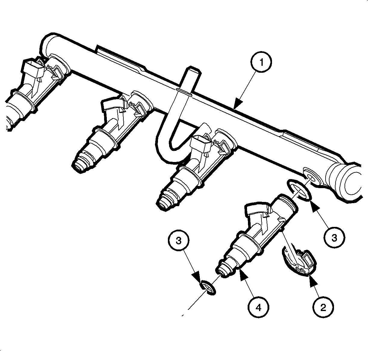
| • | Fuel Rail (1) |
| • | Injector Retainer Clip (2) |
| • | Injector O-ring Seal (3) |
| • | MFI Injector Assembly (4) |
Fuel Rail Assembly
The fuel rail assembly is mounted to the intake manifold and performs several functions. It positions the fuel injectors in the intake manifold, distributes fuel evenly to the fuel injectors, and dampens fuel pump pressure pulsations. The dampening function is performed by a helium filled, metal bladder inside the fuel rail.
Fuel Injector
The SFI fuel injector assembly is a solenoid-operated device, controlled by the PCM, that meters pressurized fuel to a single engine cylinder. The PCM energizes the (12 ohms) solenoid to open a normally closed ball valve. This allows fuel to flow into the top of the fuel injector, past the ball valve, and through a recessed flow director plate at the injector outlet. The director plate has four machined holes that control the fuel spray, generating a conical spray pattern of finely atomized fuel at the valve, causing it to become further atomized and vaporized before entering the combustion chamber.
A fuel injector that is stuck partly open or leaking would cause a loss of fuel pressure after engine shut down, so long crank times would be noticed on some engines. Dieseling also could occur because some fuel could be delivered to the engine after the ignition is turned to the OFF position.
Fuel Metering System

The fuel metering system is made up of the following parts:
| • | Fuel rail assembly, including: |
| - | Fuel injectors |
| - | Pressure regulator |
| • | Throttle body assembly, including: |
| - | Idle air control (IAC) valve |
| - | Throttle position (TP) sensor |
