Tools Required
| • | J 44015 Linkage Installer |
| • | SA91100C Tie Rod Separator |
| • | SA9132S Lower Control Arm Ball Stud Separator |
| • | SA9140E Torque Angle Gage |
Removal Procedure
- With vehicle on the ground, depress the brake pedal and loosen the axle to hub nut.
- Raise the vehicle on a hoist.
- Remove the wheel and tire assembly.
- Remove caliper mount bracket-to-steering knuckle bolts; remove the caliper assembly and suspend it from the strut spring with mechanics wire.
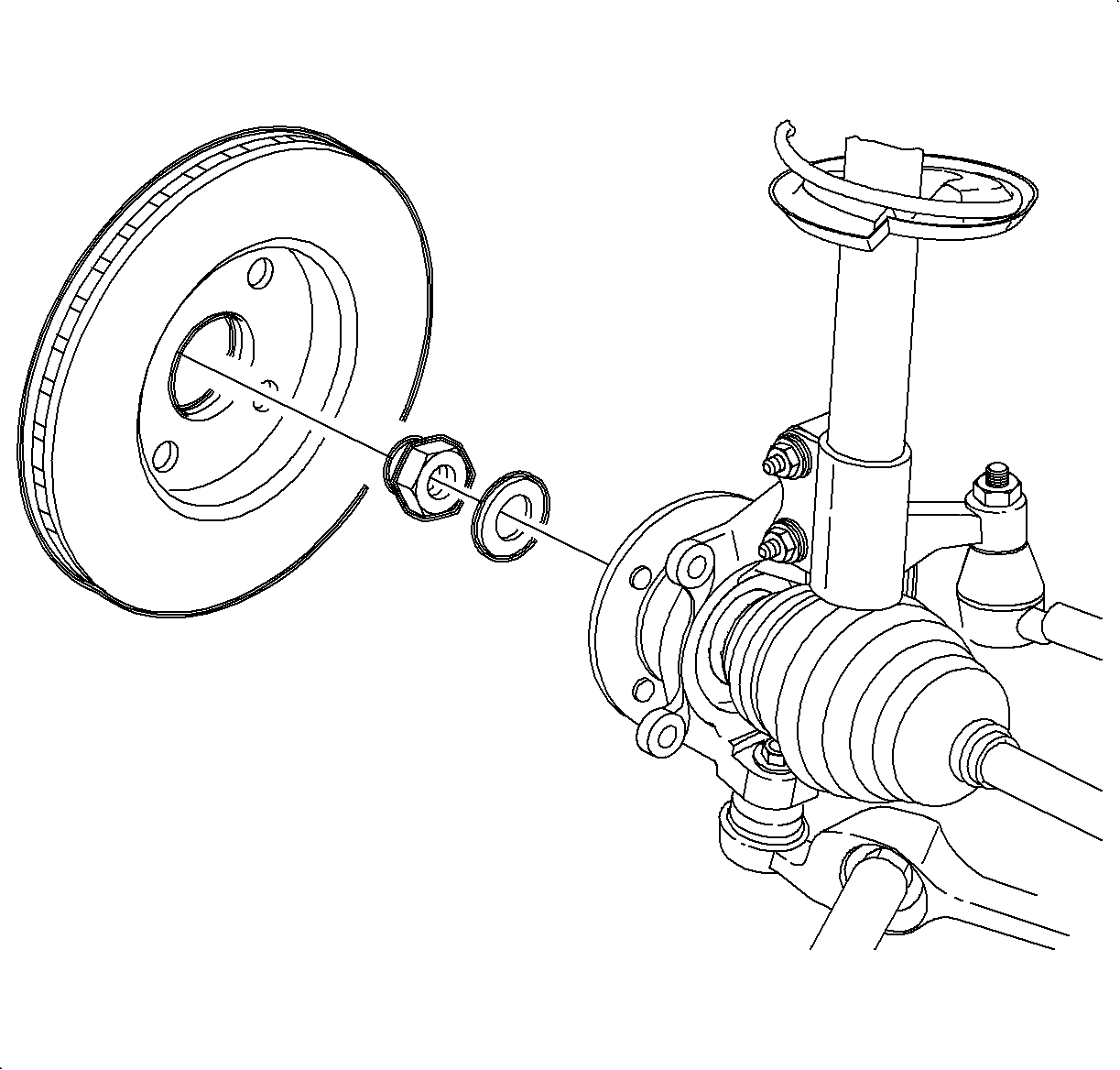
- Remove the rotor.
- Loosen the steering knuckle-to-strut fasteners.
- Remove the axle nut and washer, but do not attempt to remove the axle.
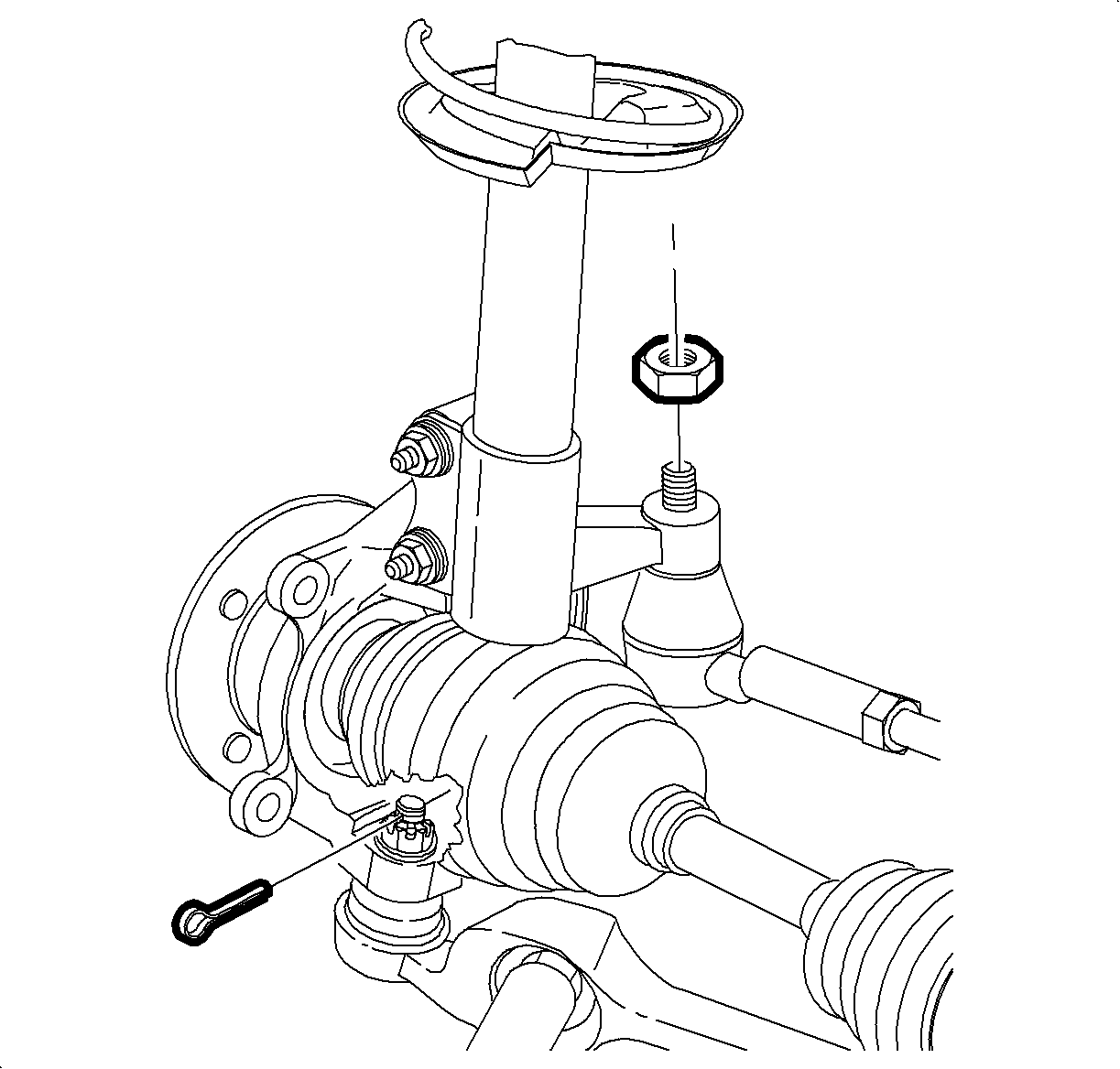
- Remove and discard the lower control arm ball stud cotter pin.
- Loosen the ball stud castle nut, until top of the castle nut is level with the top of ball the stud.
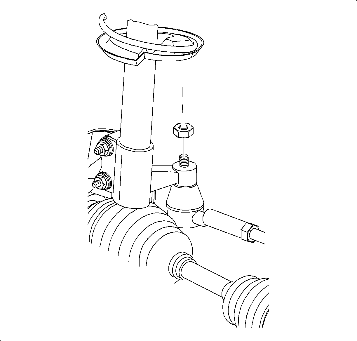
- Remove the torque prevailing nut and discard the nut. A new nut will be required during assembly.
- Using the SA9132S (or equivalent), separate the lower control arm from the steering knuckle.
- Remove the lower control arm ball stud castle nut.
- Using the SA91100C (or equivalent), separate the rod end from the steering knuckle.
- If equipped with ABS, disconnect the electrical connector at ABS wheel speed sensor.
- Support or suspend drive axle assembly.
- Remove the 2 strut-to-steering knuckle fasteners.
- Remove the knuckle/wheel hub assembly from vehicle.
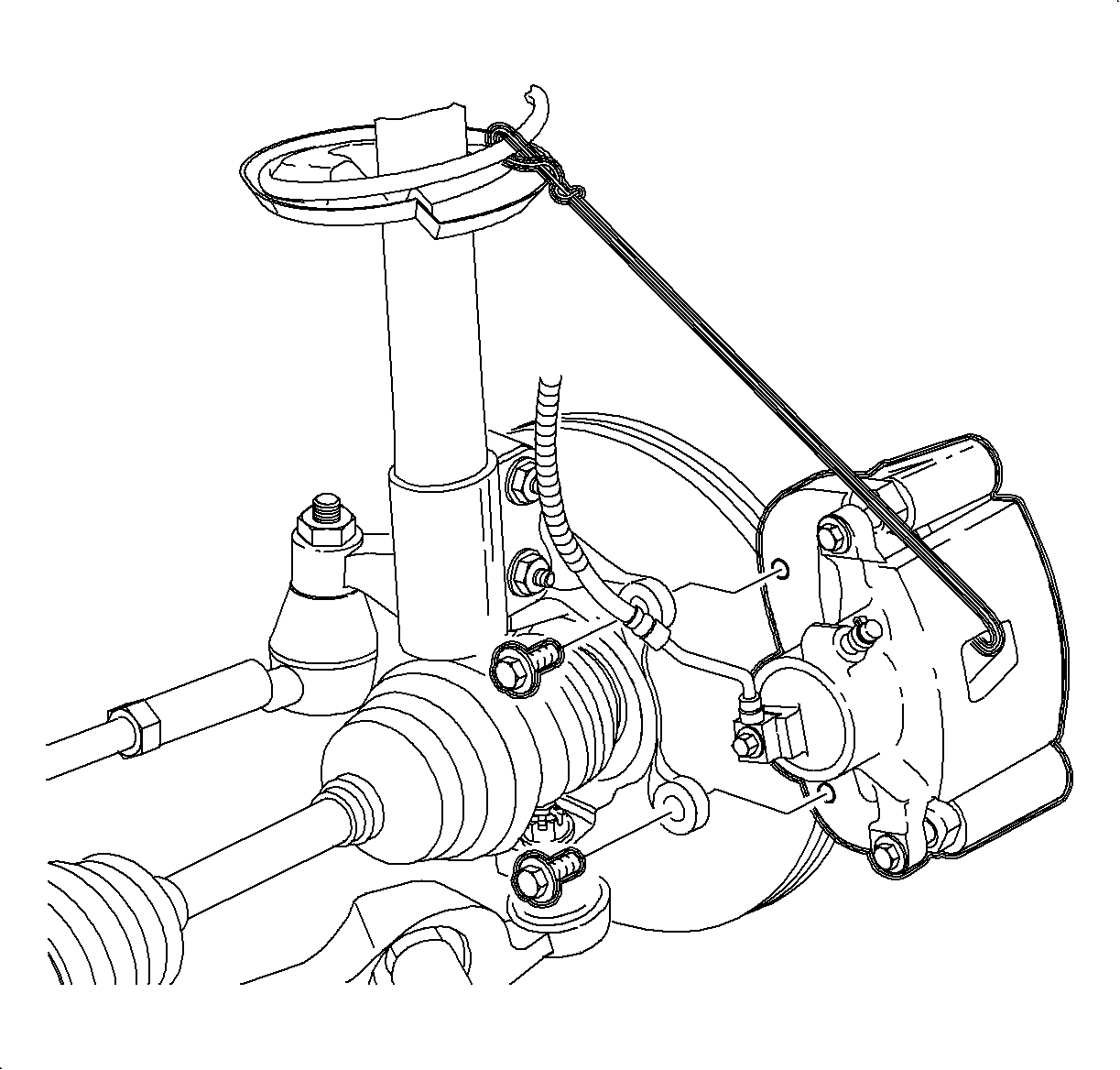
Caution: Ensure that the vehicle is properly supported and squarely positioned. To help avoid personal injury when a vehicle is on a hoist, provide additional support for the vehicle on the opposite end from which the components are being removed.
Important: Do not remove fasteners at this time.
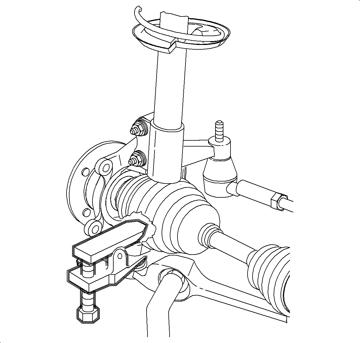
Notice: On ABS equipped vehicles, the outer CV joint has a speed sensor ring. Using the incorrect tool or procedure to separate the control arm from the knuckle can damage the ring, resulting in a loss of ABS operation.
Notice: Do not attempt to separate the joint using a wedge-type tool because seal may be damaged.
Important: Lubricate threads of tool forcing screw using thread lube before each use.
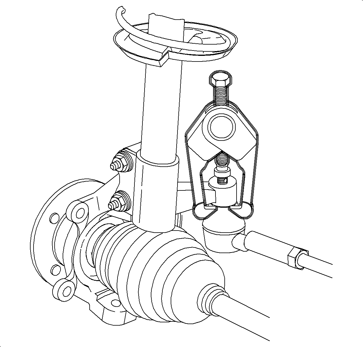
Notice: Do not attempt to separate the joint using a wedge-type tool because seal may be damaged.
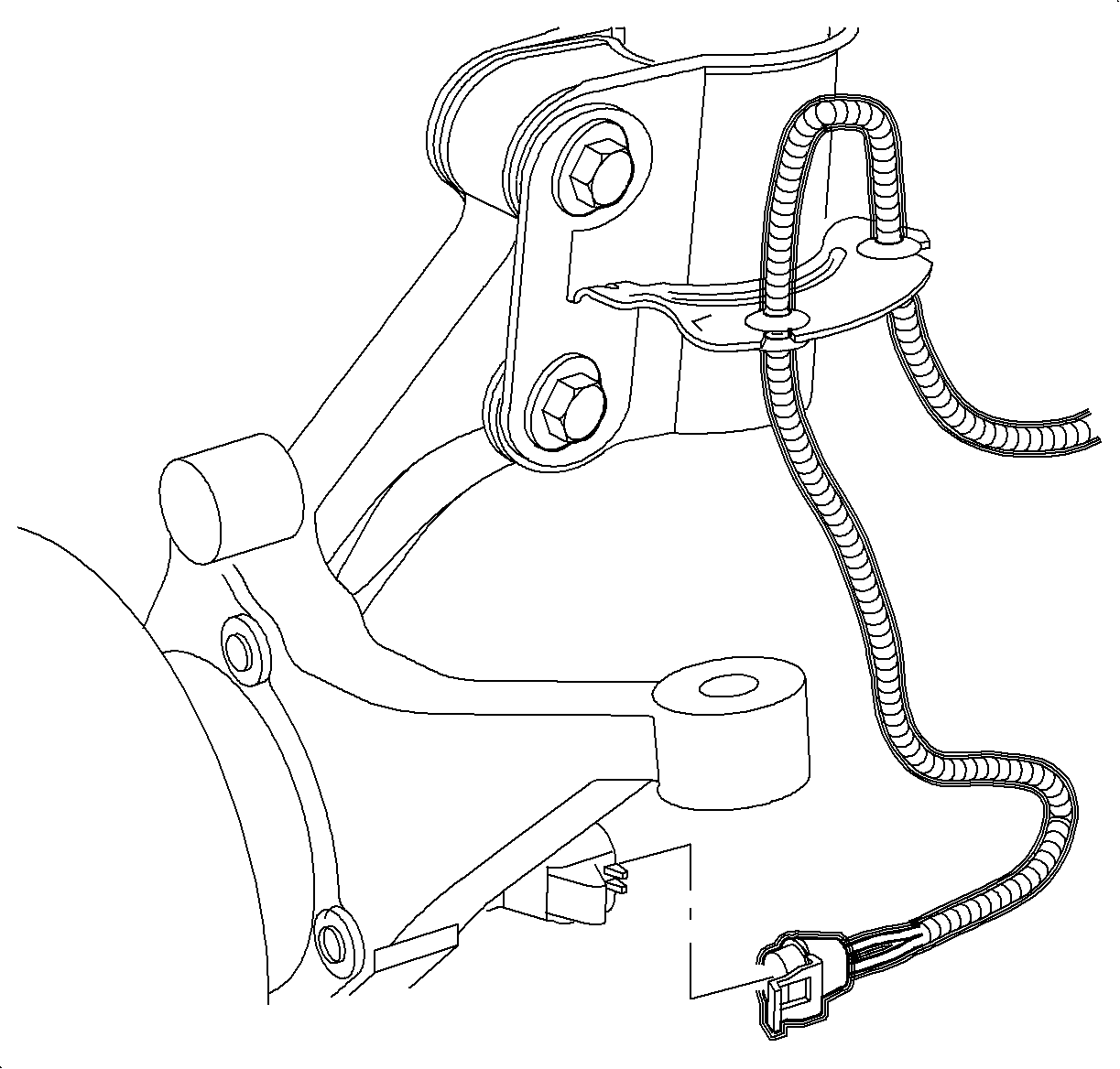
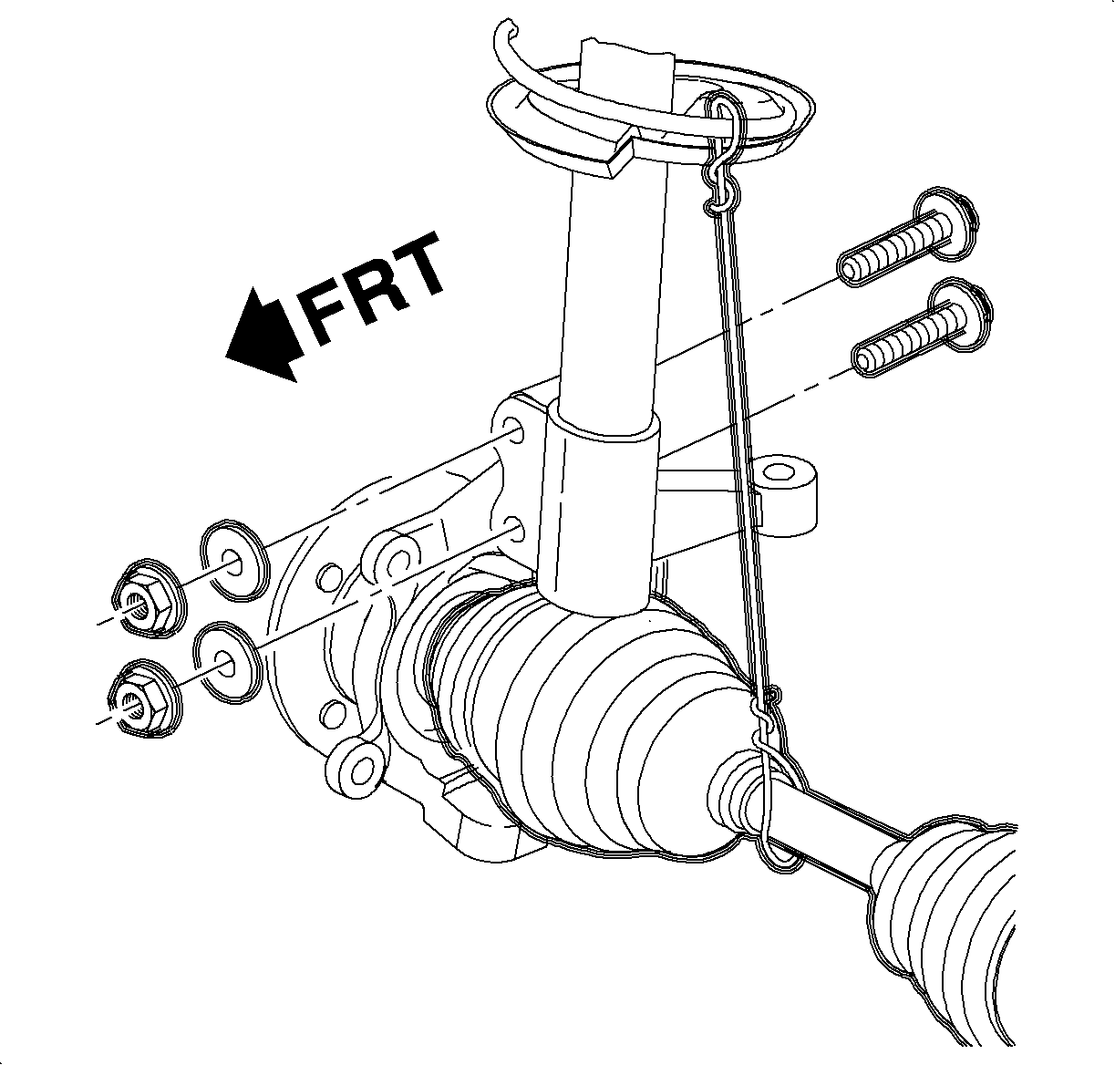
Important: Never pull on the shaft assembly.
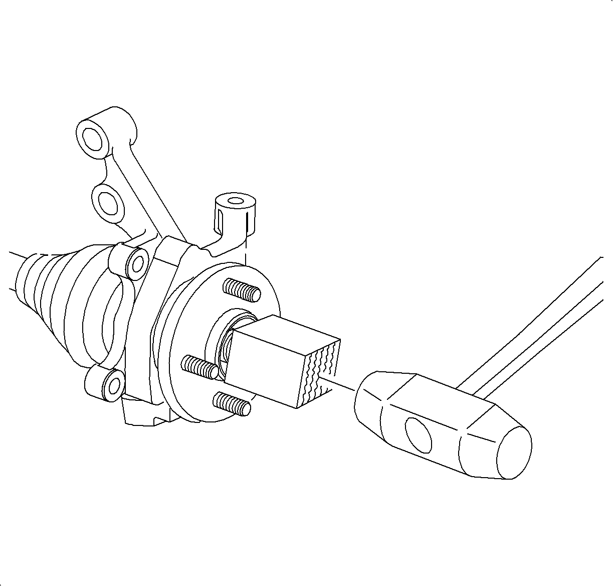
Important: If difficulty is encountered in separating axle from hub, tap on end of drive axle shaft using a block of wood and a hammer. Do not hammer directly on end of axle.
Installation Procedure
- Position steering knuckle onto axle shaft and install axle to hub washer and a NEW nut.
- Install ball joint stud through knuckle attachment point and install castle nut.
- Attach steering knuckle-to-strut with fasteners.
- Seat tie rod end into steering knuckle by using J 44015 or equivalent.
- Tighten new torque prevailing nut.
- Tighten steering knuckle-to-strut fasteners.
- Tighten ball joint stud castle nut.
- Install new cotter pin.
- Install rotor onto wheel hub.
- Install caliper mount bracket onto knuckle.
- If equipped with ABS, install electrical connector to ABS wheel speed sensor.
- Depress brake pedal and tighten axle to hub nut.
- Position wheel onto hub.
- Install wheel nuts and tighten in a crisscross pattern. Repeat tightening pattern to make sure torque is correct.
- Lower vehicle from hoist.
- Perform vehicle wheel alignment. Refer to Wheel Alignment Specifications
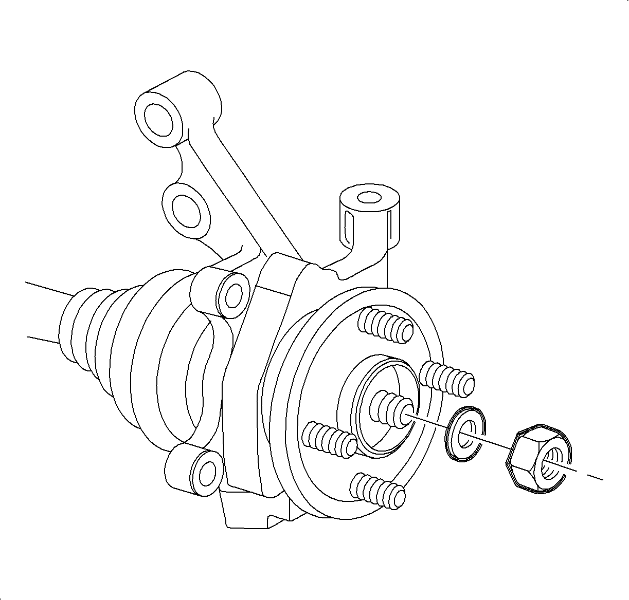
Important: Do not tighten nut at this time.
Important: Do not tighten nut at this time.
Important: Tie rod end threads must be thoroughly cleaned before tightening nut. Do not lubricate any portion of the stud.
Important: Use new nut. Torque retention of old nut may not be sufficient.
Tighten
Tighten the tie rod linkage installer to 45 N·m (33 lb ft).
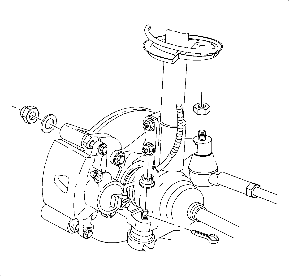
Important: This procedure requires SA9140E (or equivalent).
Tighten
Tighten tie rod-to-steering knuckle nut to 25 N·m (18 lb ft) plus 90 degrees.
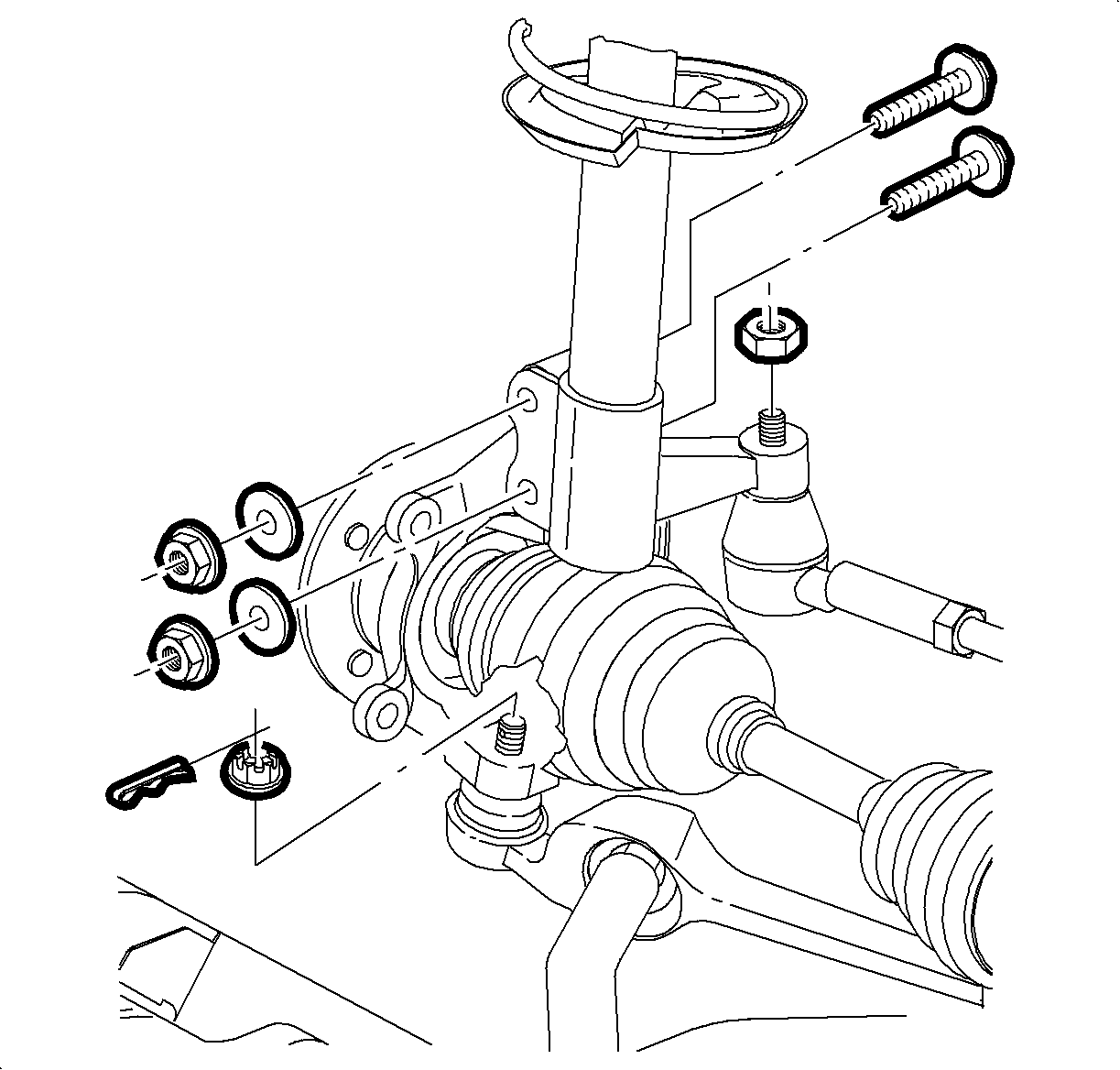
Important: With fasteners installed but not tightened, push bottom of strut inward while tightening fasteners.
Tighten
Tighten the steering knuckle-to-strut fastener to 170 N·m (126 lb ft).
Important: If it is necessary to rotate the castle nut after tightening to orient it to the hole in the stud, always tighten the nut to align it; never loosen it.
Tighten
Tighten the ball joint stud castle nut to 75 N·m (55 lb ft).

Tighten
Tighten the caliper mount bracket-to-steering knuckle to 110 N·m (81 lb ft).

Tighten
Tighten the axle-to-hub nut to 200 N·m (148 lb ft).
Notice: Before installing wheels, remove rust or corrosion from wheel mounting surfaces and brake rotors/drums. Failure to do so can cause wheel nuts to loosen in service.
Tighten
Tighten the wheel nuts to 140 N·m (103 lb ft).
