For 1990-2009 cars only
Tools Required
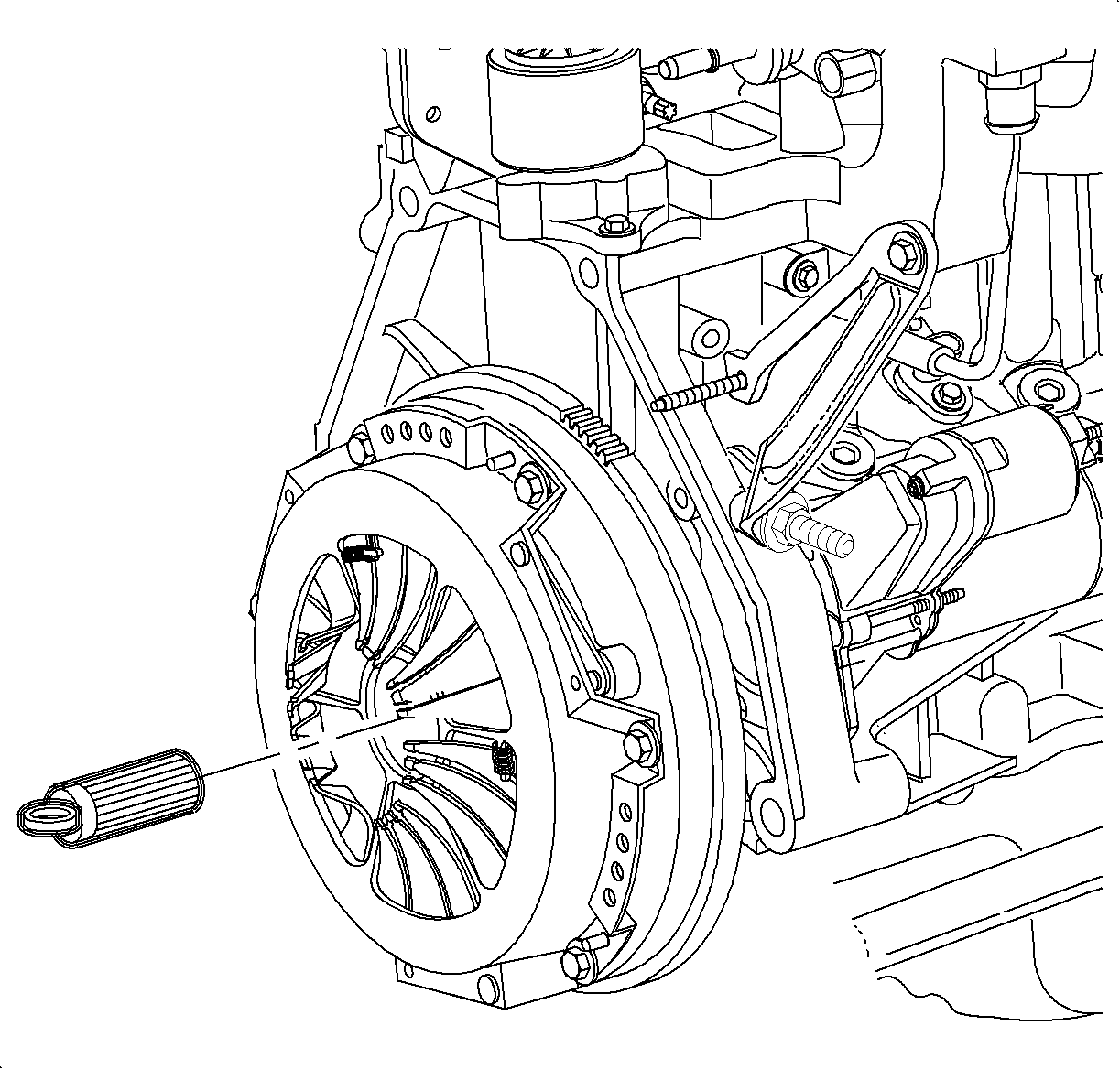
SA9145T M/T Clutch Aligner
Removal Procedure
- Remove the transaxle from vehicle . Refer to Transmission Assemble removal procedure.
- Remove the release fork and bearing from transaxle by unsnapping fork from ball stud.
- Seperate the release bearing from release fork by sliding the bearing from the fork.
- Check the release bearing for excessive play and for minimal bearing drag. Replace the bearing if excessive play or no/little drag is found.
- Use a feeler gage to measure the distance between clutch housing cover assembly (pressure plate) and flywheel surfaces to determine clutch disc facing thickness. Replace disc if not within specification.
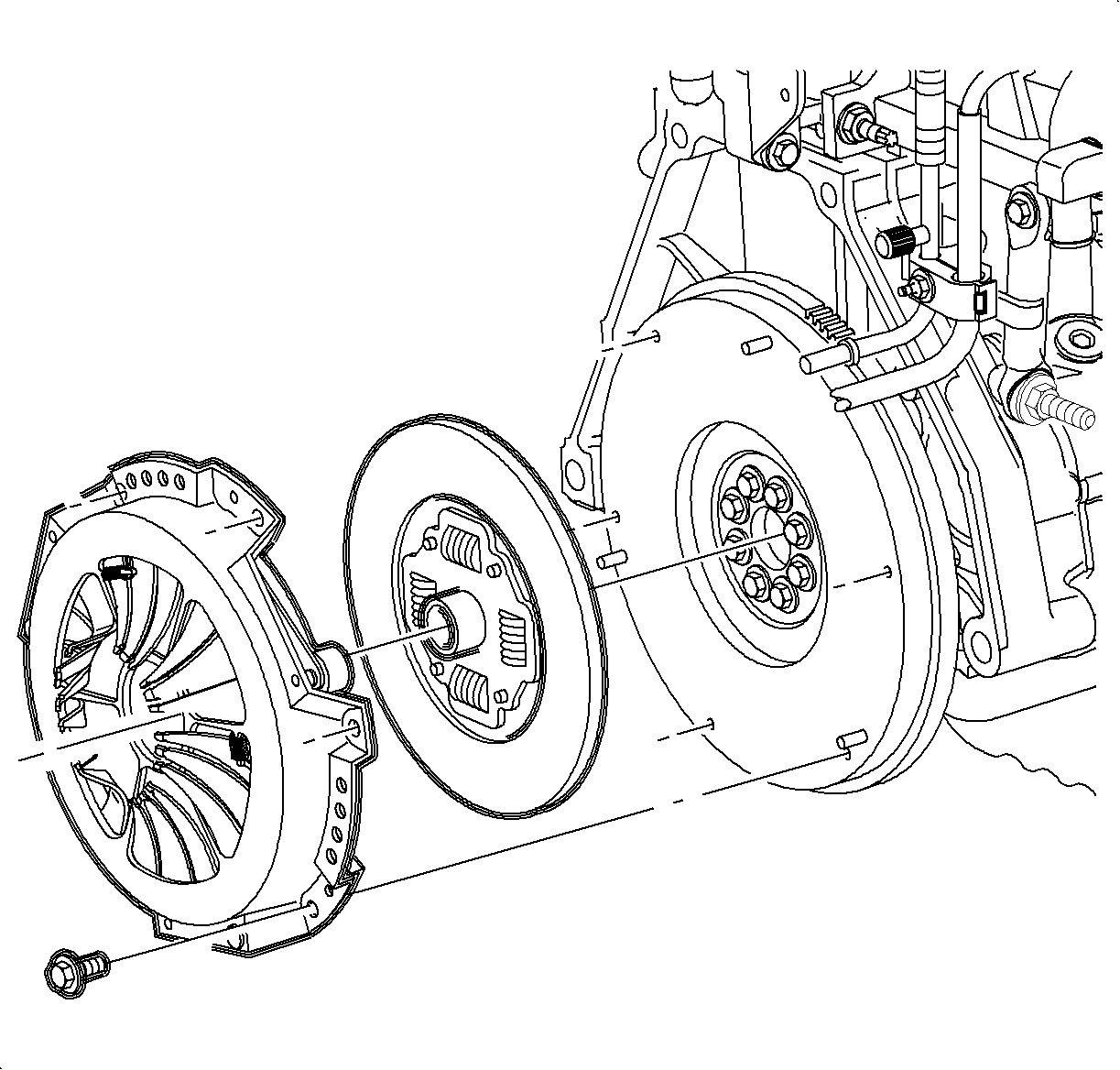
- Remove the clutch housing cover assembly (pressure plate to flywheel bolts.
- Remove the clutch housing cover assembly and clutch disc.
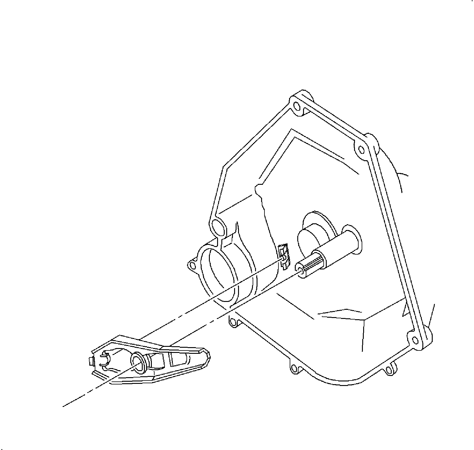
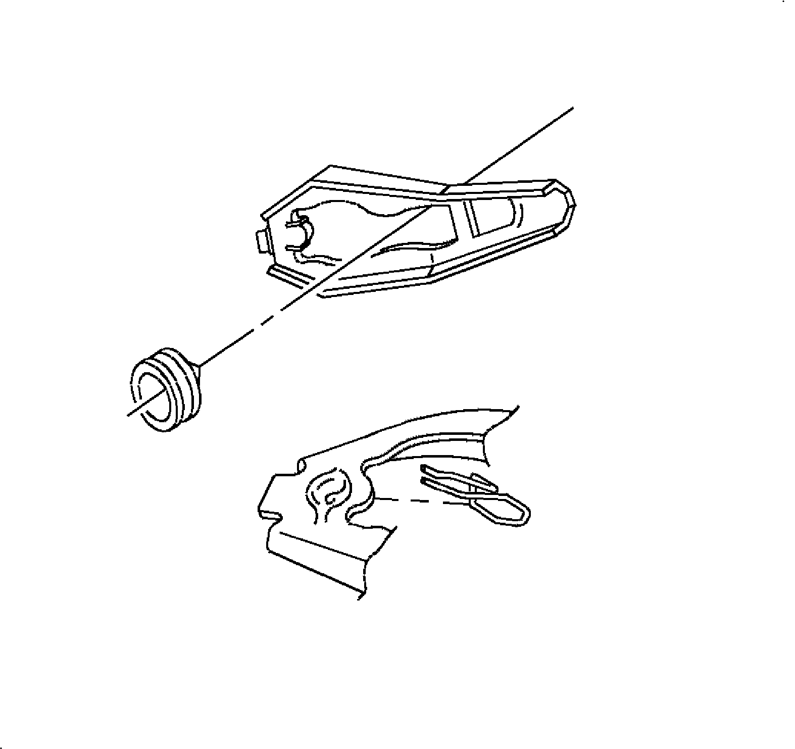
Important: The release bearing is packed with grease and may not be washed in solvent
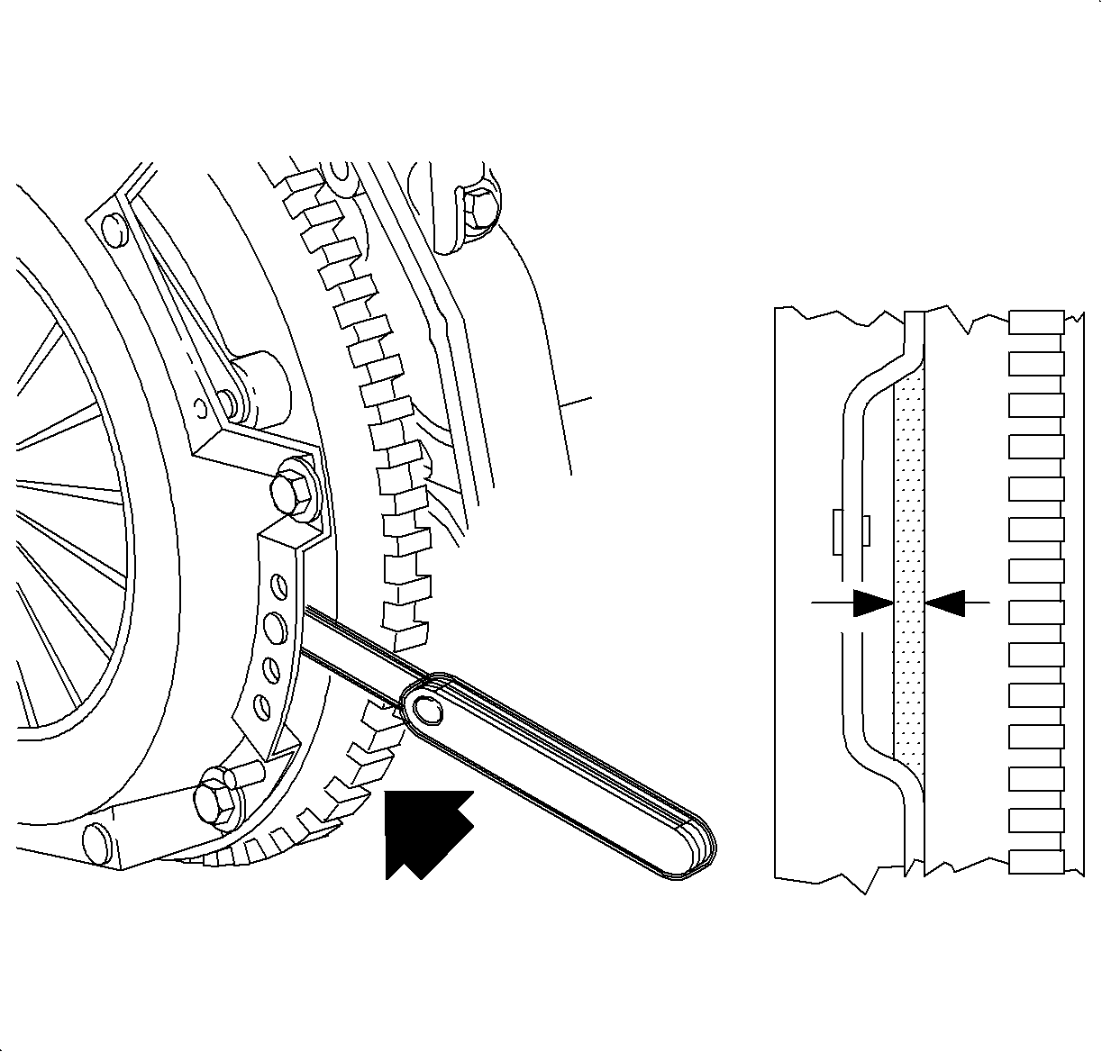
Clutch Disc Facing Thickness
Specifications
Thickness Range: 4.65-701. mm (0.18-0.28 in).
Inspection Procedure
- Inspect clutch housing cover assembly surface for excessive wear, chatter marks, cracks or overeheating (indicated by blue discoloration). Replace clutch housing cover assembly if damaged
- Check for clutch housing cover assembly warpage using a straight edge and feeler gage.
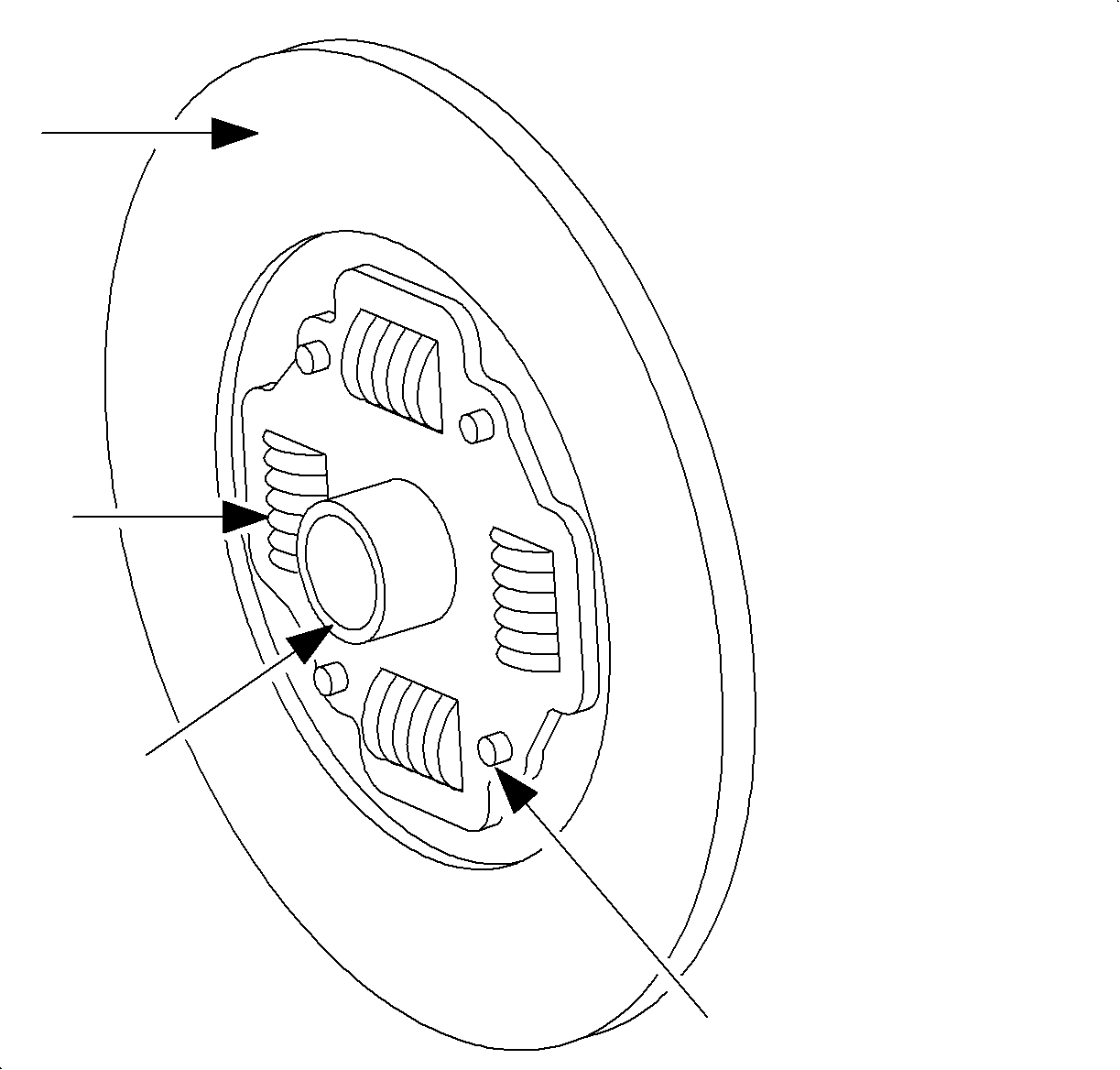
- Check the clutch disc facings for oil or burnt spots. Replace the clutch disk if necessary.
- Check the disc for loose damper springs, hub, or rivets. Replace disc if any are broken or excessively loose
- Inspect the flywheel ring gear for wear or damage. Replace the flywheel if damaged
- Check the flywheel to clutch disc contact surface for wear, cracks, chatter marks, or overheating (indicated by blue discloration). Repair or replace flywheel if necessary.
- Measure the flywheel runout using a dial indiacator for at least two revolutions. Measure the runout at a diameter junt inside the clutch housing cover (pressure plate) bolt holes. Push the crankshaft forward to take up thrust bearing clearance. Repair or replace flywheel if not within specification
- Check the flywheel for warpage using a straight edge and feeler gage.
- Remove the flywheel-to-crankshaft bolts and remove flywheel.
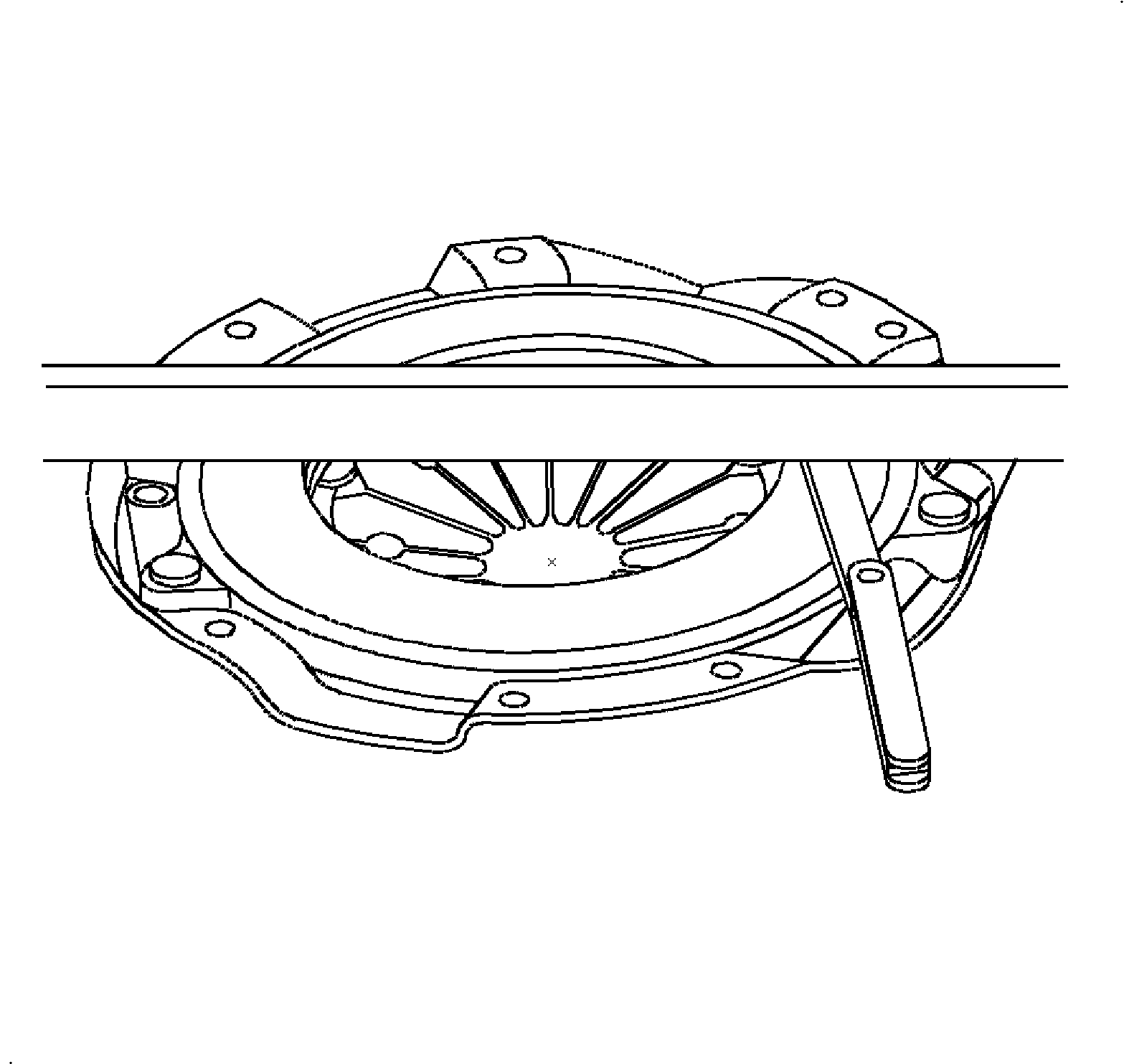
Important: Black random spotting on friction surface of clutch housing cover assembly (pressure plate) is normal.
Clutch Housing Cover Assembly Warpage
Specifications
Maximum: 0.15 mm (0.006 in).
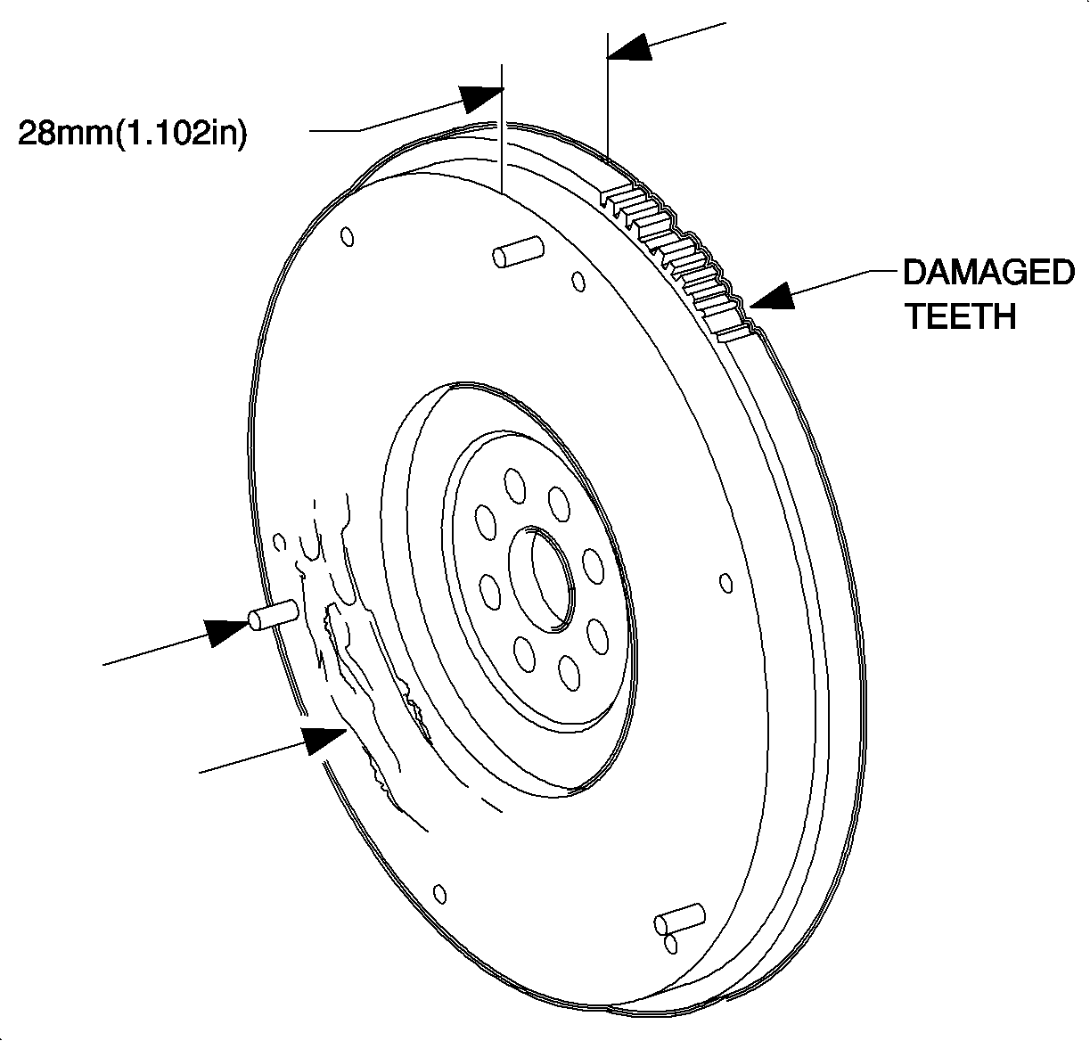
Important: Black random spotting on friction surface of flywheel is normal.
Flywheel Thickness
Specifications
Minimum: 28 mm (1.102 in).
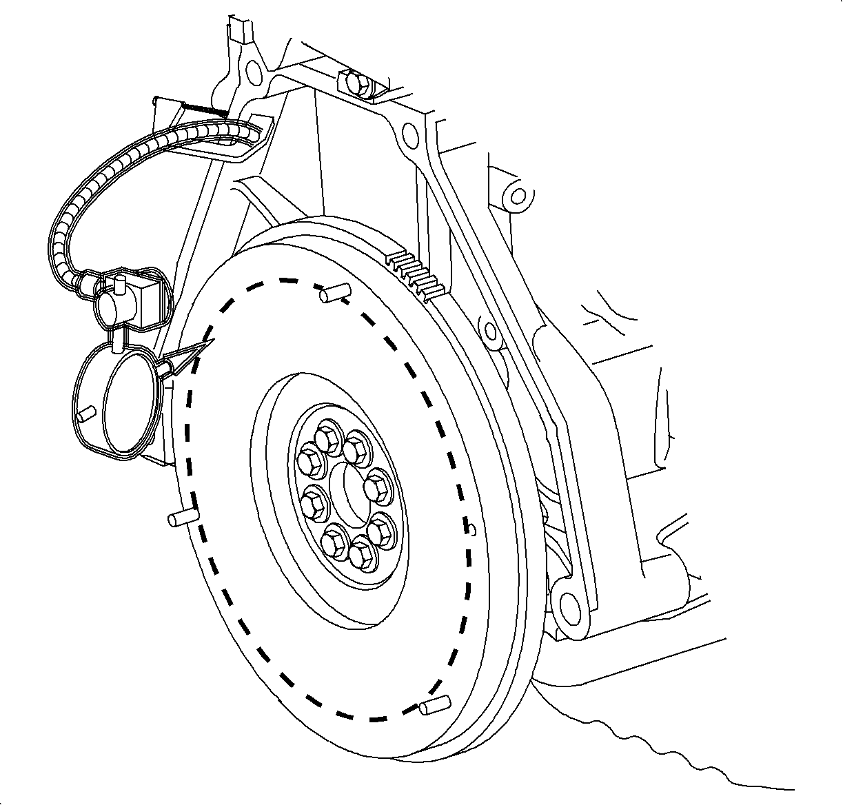
Flyout Runout
Specification
Maximum: 0.15 mm (0.006 in).
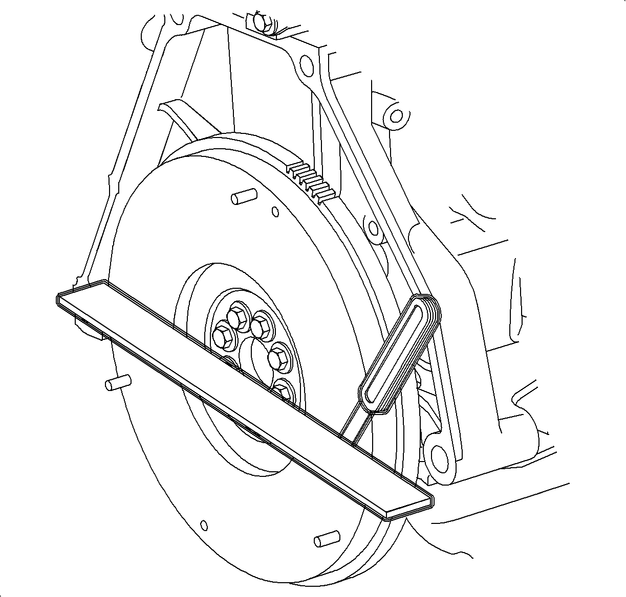
Flywheel Warpage
Specifications
(Maximum) : 0.05 mm (0.006 in).
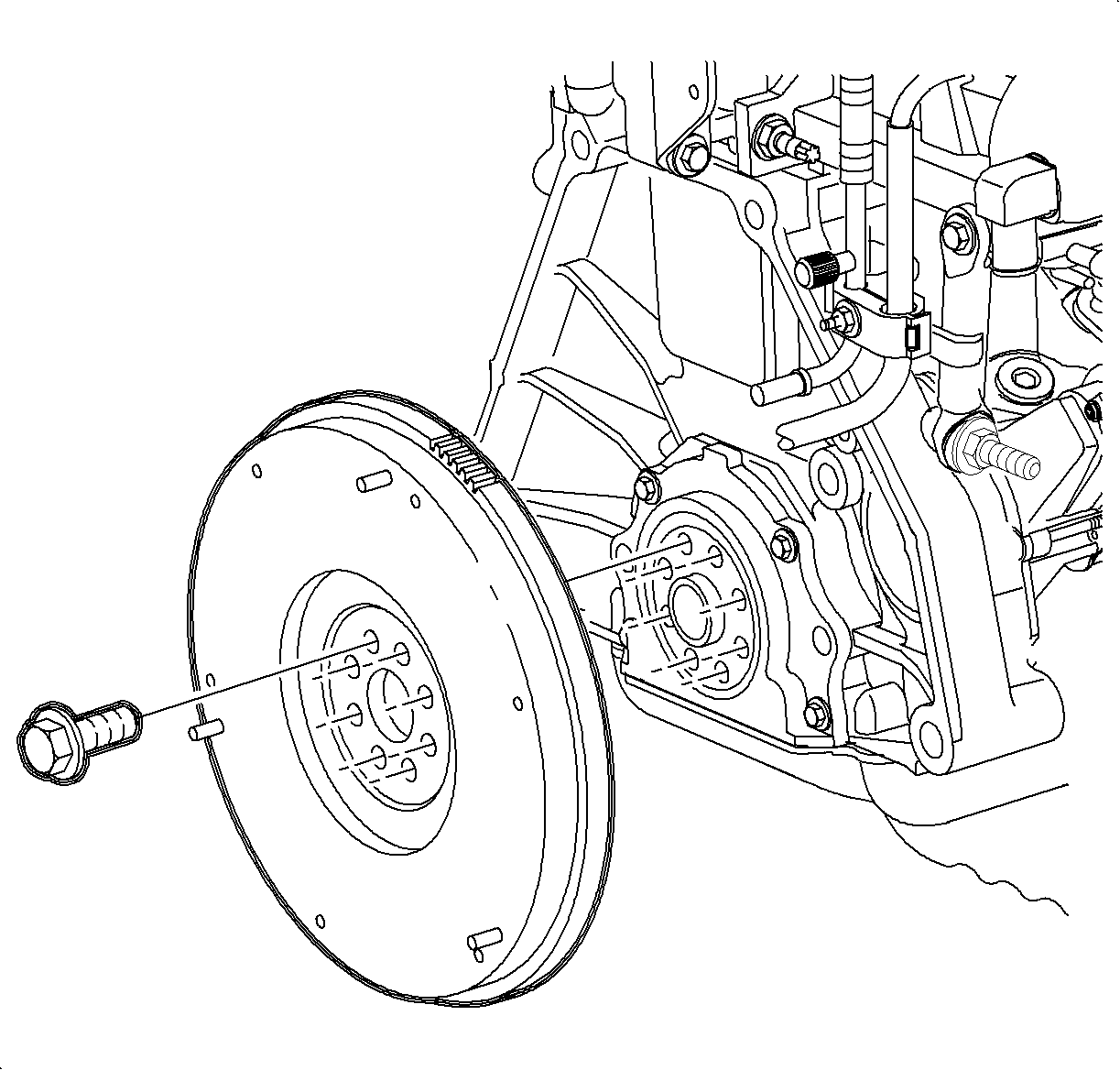
Installation Procedure
- Install the flywheel-to-crankshaft and start bolts.
- Tighten the bolts in a crisscross pattern.
- Install the M/T Clutch Aligner SA9145T in the clutch disc and push in until it bottoms out in the crankshaft.
- Install clutch disc and clutch housing civer assembly (pressure plate) with purple dot on clutch housing cover assembly aligned as close as possible to the mark on flywheel. Position the clutch sisc so that the side marked "FLYWHEEL SIDE" is toward flywheel. Start clutch housing cover assembly to flywheel bolts.
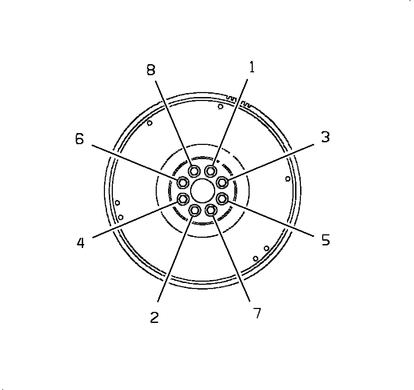
Tighten
Tighten the flywheel-to-crankshaft bolts (in crisscross pattern) to 80 N·m(59 lbs ft).

