Removal Procedure
- Ensure the ignition is OFF.
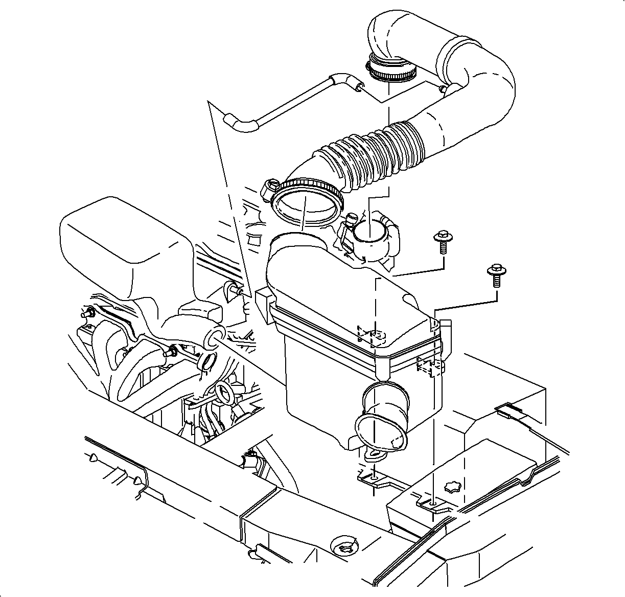
- Remove the air cleaner and duct assembly. Refer to Air Cleaner Housing and Duct Assembly Replacement in HVAC.
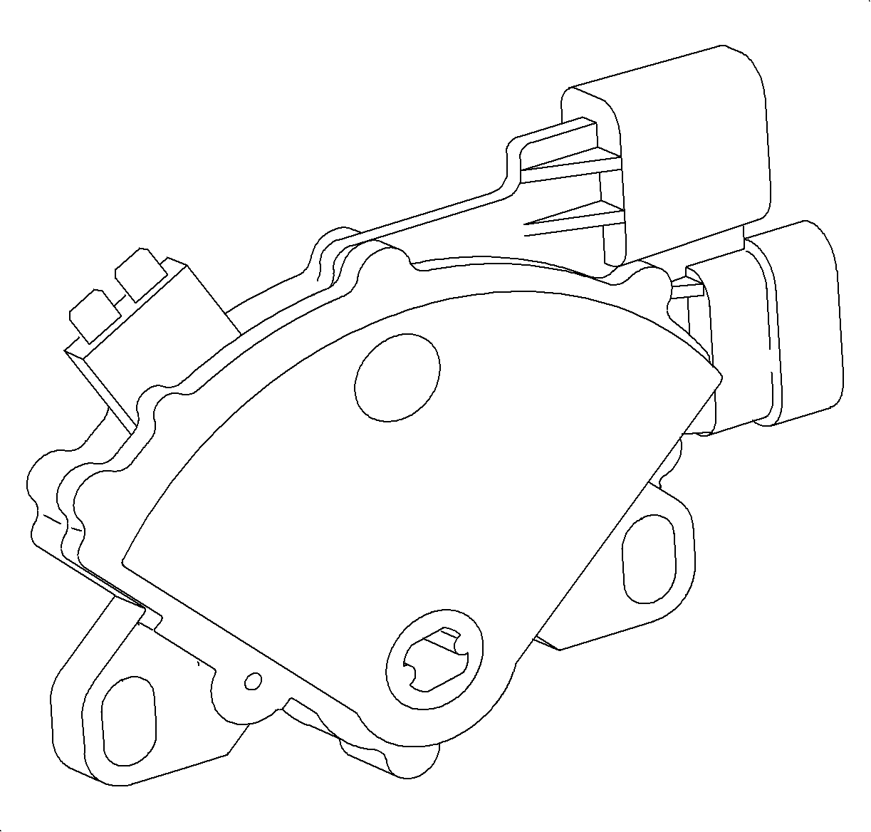
- Disconnect the transaxle range switch harness connectors.
- Place the control lever in the full clockwise position.
- Prevent the manual shift shaft from rotating by holding the control lever while removing the retaining nut from the manual shift shaft. Remove the control lever.
- Remove the 2 switch-to-transaxle case bolts and remove the switch.


Notice: If manual shift shaft is rotated excessively, internal damage to the transaxle range switch may occur.
Installation Procedure
- Install the switch to the transaxle and install the switch-to case bolts. Do not tighten bolts at this time.
- Install the control lever-to-manual shift shaft.
- Prevent the manual shift shaft from rotating by holding the control lever while installing the retaining nut.
- Install the cable to the control lever and adjust the cable. Refer to Shift Control Cable Adjustment .
- Before tightening the transaxle range switch-to-case bolts, proceed to the Adjustment procedure.

Notice: If manual shift shaft is rotated excessively, internal damage to the transaxle range switch may occur.
Tighten
The transaxle control lever-to-manual detent shaft nut to 12 N·m
(9 lb ft).
Adjustment Procedure
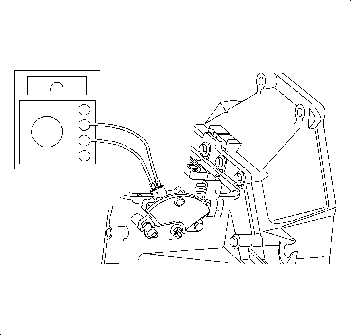
- Place the transaxle in Drive (D). Use an ohmmeter or continuity tester to check for continuity across terminals on the selector switch. Rotate the transaxle range switch from the left fender towards the engine until continuity is achieved.
- Tighten the switch-to-case bolts. After switch-to-case bolts have been tightened, check continuity.
- Connect the transaxle range switch harness connectors.
- Install the air cleaner and duct assembly. Refer to Air Cleaner Housing and Duct Assembly Replacement in HVAC.
- Using a scan tool, ensure each gear position reads correctly while manually moving through all gears.

Important: While adjusting the transaxle range switch, always rotate the switch towards the engine to achieve continuity. A diagnostic trouble code DTC P0706 could result if this procedure is not followed.
Important: Digital volt/ohm meter (DVOM) with audible continuity test is preferred. Do not stick the probe in the transaxle range switch terminal hole; use male terminals on the transaxle range switch or faulty readings could occur.
Notice: Refer to Fastener Notice in the Preface section.
Tighten
Tighten the transaxle range switch-to-case bolts to 14 N·m (10 lb ft).

