For 1990-2009 cars only
Removal Procedure
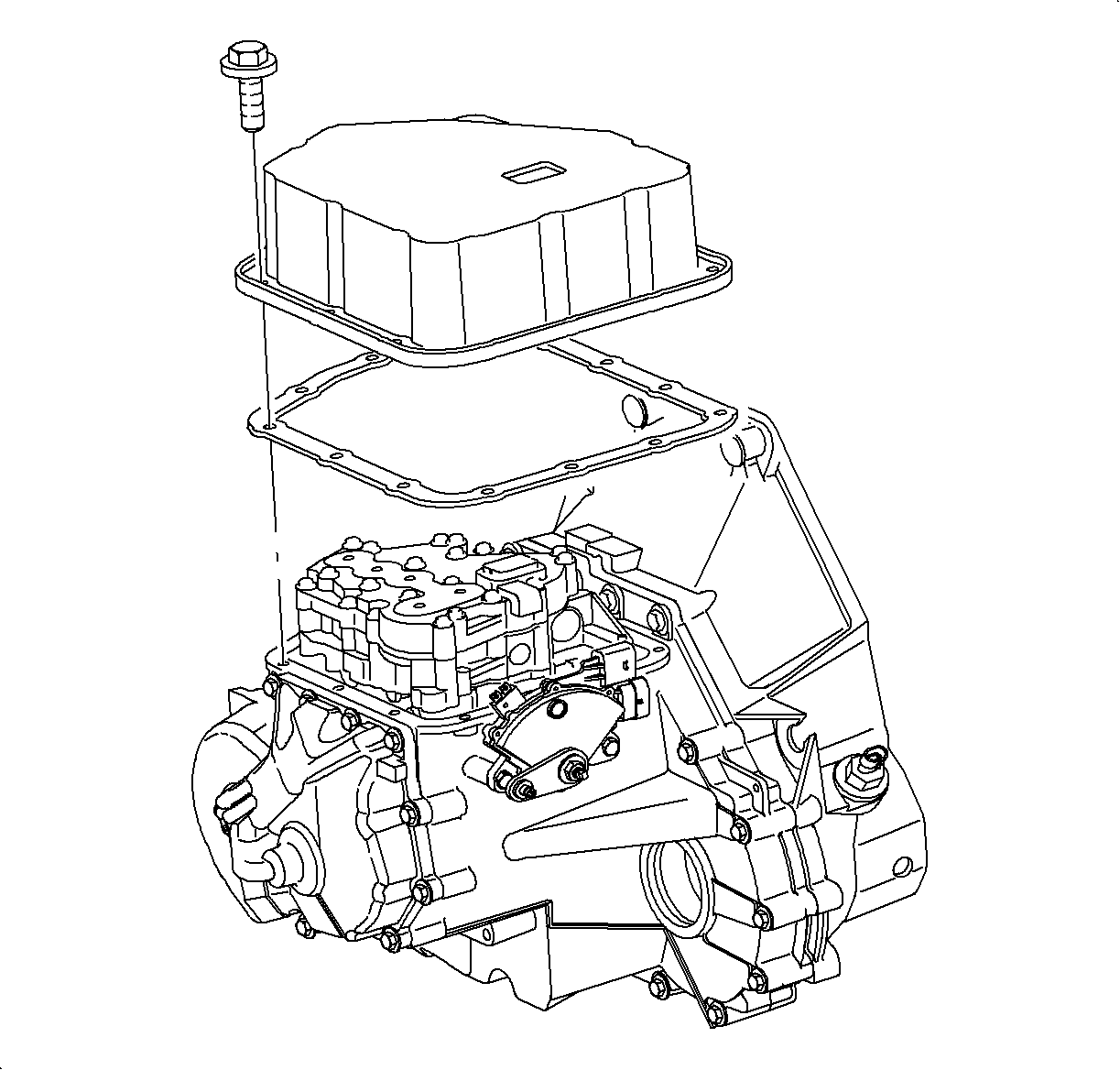
- Remove the valvebody. Refer to Control Valve Body Assembly Removal .
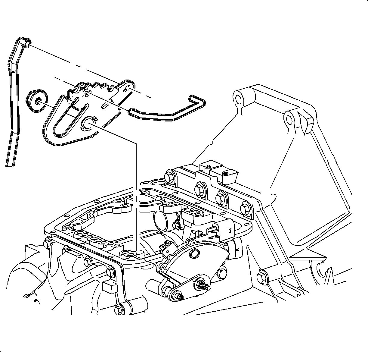
- Remove the nut retaining the manual detent lever to the manual shift shaft.
- Remove the manual detent lever from the manual shift shaft and disengage the park pawl lever from it.
- Remove the manual detent lever and the manual valve link from the transaxle.

Notice: If manual shift shaft is rotated excessively, internal damage to the transaxle range switch may occur.
Important: Place a clean rag in the transaxle case under the manual detent lever to catch the nut in case it is dropped.
Installation Procedure
- Install the manual valve link to the manual detent lever.
- Prevent the manual shift shaft from rotating by holding control lever.
- Install the attachment nut and torque.
- Remove the rag from the transaxle case.
- Install the valvebody. Refer to Control Valve Body Assembly Removal .

Notice: If manual shift shaft is rotated excessively, internal damage to the transaxle range switch may occur.
Notice: Refer to Fastener Notice in the Preface section.
Tighten
Tighten the manual detent lever-to-manual detent shaft nut to 12 N·m
(9 lb ft).

