Tools Required
SA9119T Input Shaft Holding Tool
Removal Procedure
- Remove the end cover. Refer to End Cover Replacement .
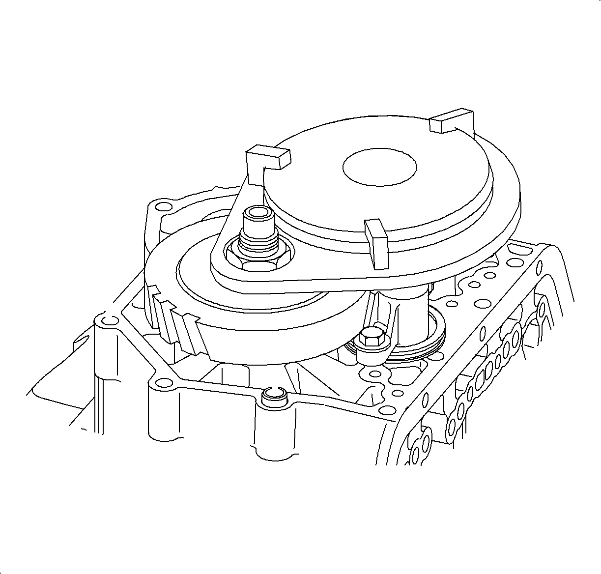
- Install the SA9119T .
- Remove the input shaft nut.
- Remove the holding tool, and remove the output shaft nut.
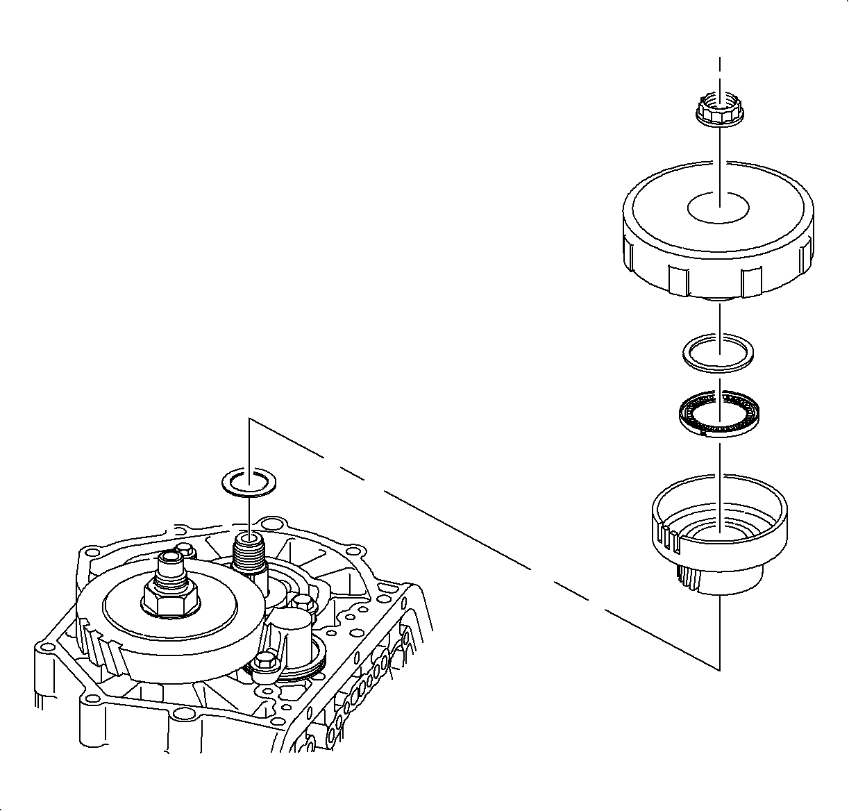
- Remove the 1st clutch housing and 1st drive gear from the input shaft.
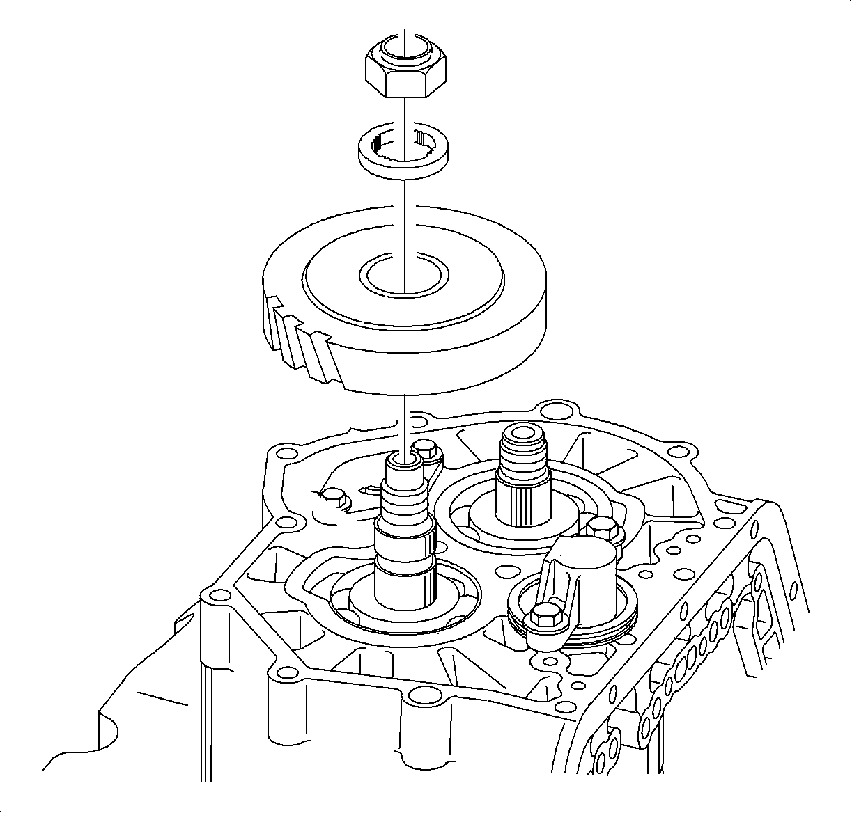
- Remove the 1st driven gear, sprag clutch, and thrust washer from the output shaft.
Installation Procedure
- Install the 1st driven gear and sprag assembly on the output shaft.
- Install the 1st driven gear thrust washer on the output shaft.
- Hand start the new output shaft clamp nut. Tighten the nut with a torque wrench.
- Lay the 1st clutch housing on a flat surface.
- Apply a generous amount of petroleum jelly to hold the 1st drive gear thrust washer in place and install the 1st drive gear thrust washer on the 1st clutch housing assembly hub.
- Install the thrust bearing with the rollers (down) toward the 1st drive gear thrust washer.
- Install the 1st drive gear and the hub assembly into the 1st clutch housing assembly by twisting the gear to align the gear hub with the clutch tangs.
- When installing the 1st drive gear and hub assembly into the clutch pack, rotate the gear and hub assembly back and forth to align the clutch plates. If you are not sure that all of the clutch plates have been engaged, lift the gear out of the clutch housing and verify that all clutch tangs are aligned.
- Install 1st drive gear thrust washer.
- Hold the 1st drive gear and hub assembly together and install it on the input shaft.
- Install the 1st drive gear and hub assembly, and 1st clutch housing assembly on the input shaft.
- Install the SA9119T .
- Hand start the new input shaft clamp nut. Tighten the nut with a torque wrench.
- After the input and output shaft nuts have been installed, verify proper operation.
- Install end cover. Refer to End Cover Replacement .

Notice: Refer to Fastener Notice in the Preface section.
Notice: Use a new nut due to insufficient torque retention of old nut. Clean shaft threads with a wire brush. When tightening and torquing this nut it must be done quickly with a hand wrench or torque wrench. If not done quickly, the thread locking material used on the new nut will cure in a short time resulting in an incorrect torque. Using a power tool will generate excess heat in the fastener causing a incorrect torque.
Tighten
Tighten the output shaft clamp nut to 150 N·m (111 lb ft).
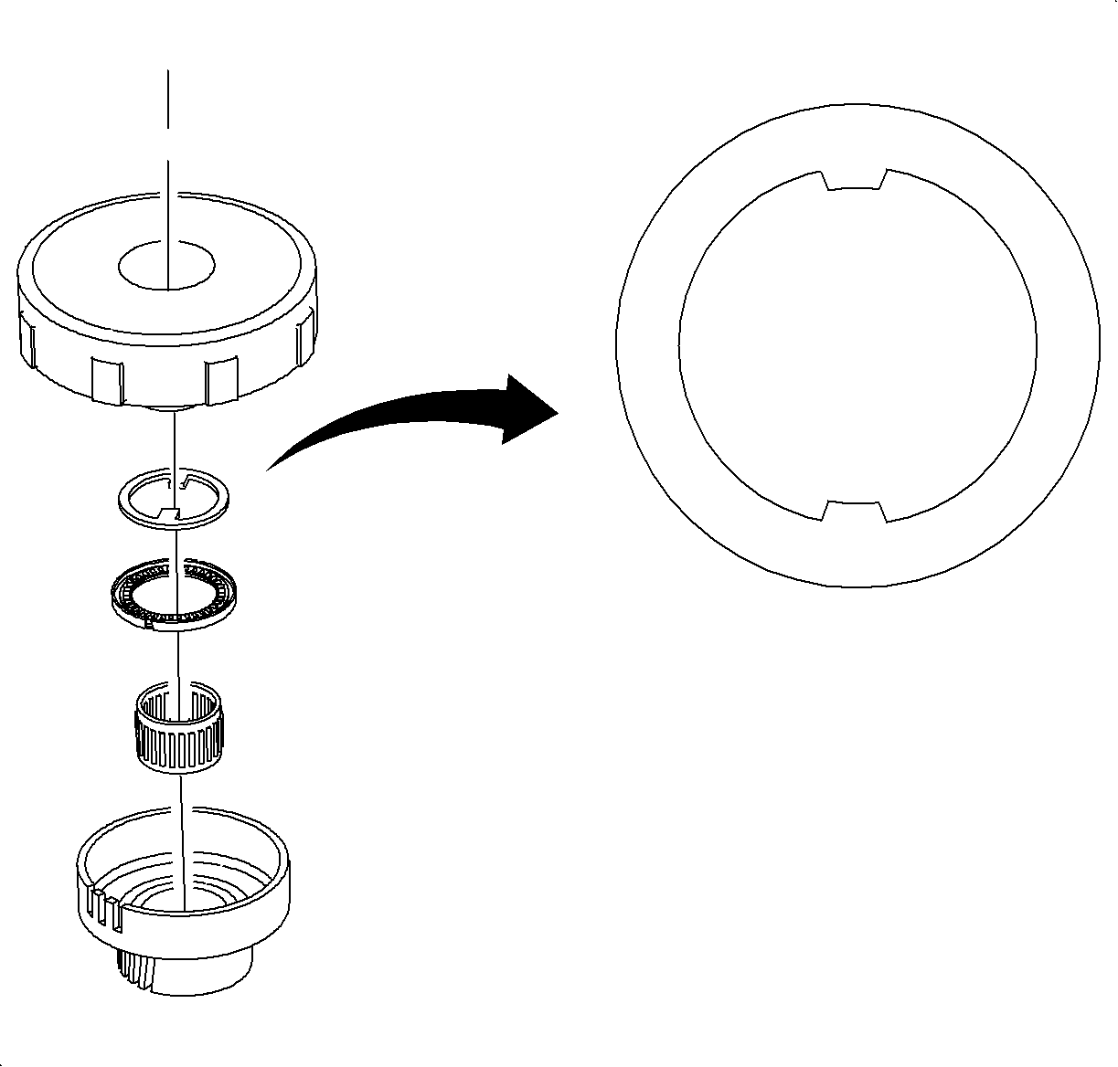
Notice: Make sure tabs on 1st drive gear thrust washer line up with slots on the 1st clutch housing assembly hub or damage to the 1st drive gear thrust washer will occur.
Important: The chamfer side goes toward the clutch housing and the flat side goes toward 1st gear.
Install the 1st clutch, and the clutch (needle) bearing.
Important: If the assembly is not held together, the gear hub may slide out of the clutch housing, which may allow the 1st gear thrust washer to move out of location, or allow the clutch plates to be pinched when the input shaft nut is tightened.
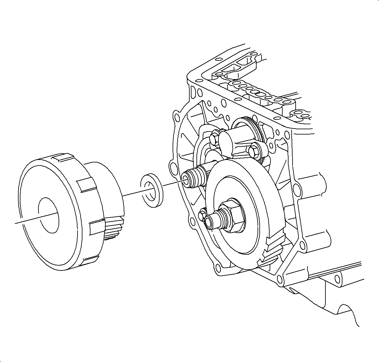

Notice: Use a new nut due to insufficient torque retention of old nut. Clean shaft threads with a wire brush. When tightening and torquing this nut it must be done quickly with a hand wrench or torque wrench. If not done quickly, the thread locking material used on the new nut will cure in a short time resulting in an incorrect torque. Using a power tool will generate excess heat in the fastener causing a incorrect torque.
Tighten
Tighten the input shaft clamp nut to 150 N·m (111 lb ft).
| • | Engage the park pawl. |
| • | Rotate the input shaft by turning the 1st clutch housing in both directions. The clutch housing should turn freely in both directions. |
| - | If the input shaft turns freely in only one direction, the 1st clutch is binding. Disassemble the 1st gear and clutch assembly and follow the steps in this procedure. |
| - | If the input shaft will not turn freely in either direction, the 2nd, 3rd or 4th clutch is binding. Refer to proper repair procedure. |
| - | If the input shaft turns freely in both directions, refer to next step. |
