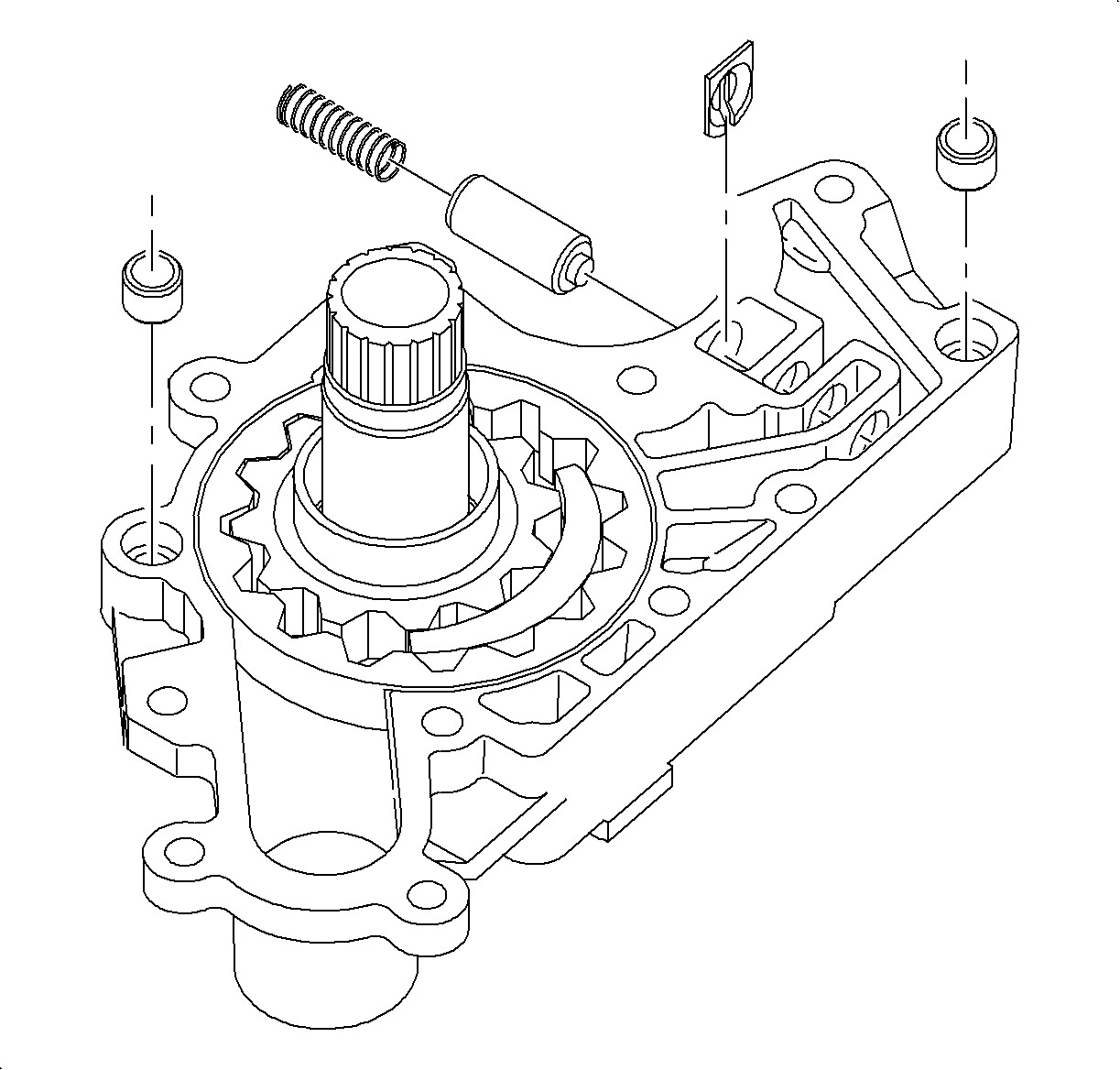
For 1990-2009 cars only
- Install the pump driven gear with chamfered side down. Chamfer is on the outer diameter of the gear.
- Install the pump drive gear.
- Using a depth micrometer, measure pump hosing face height to drive gear face and driven gear face height. If equipment is not available, place straight edge across pump face. Check drive gear face to straight edge clearance and check driven gear to straight edge clearance.
- Measure driven gear-to-pump housing clearance.
- Measure driven gear-to-crescent clearance.
- Measure drive gear-to-crescent clearance.
- Clean and install the lube relief valve, spring, and retainer.
- Install the pump wear plate. Make sure the surface is clean.
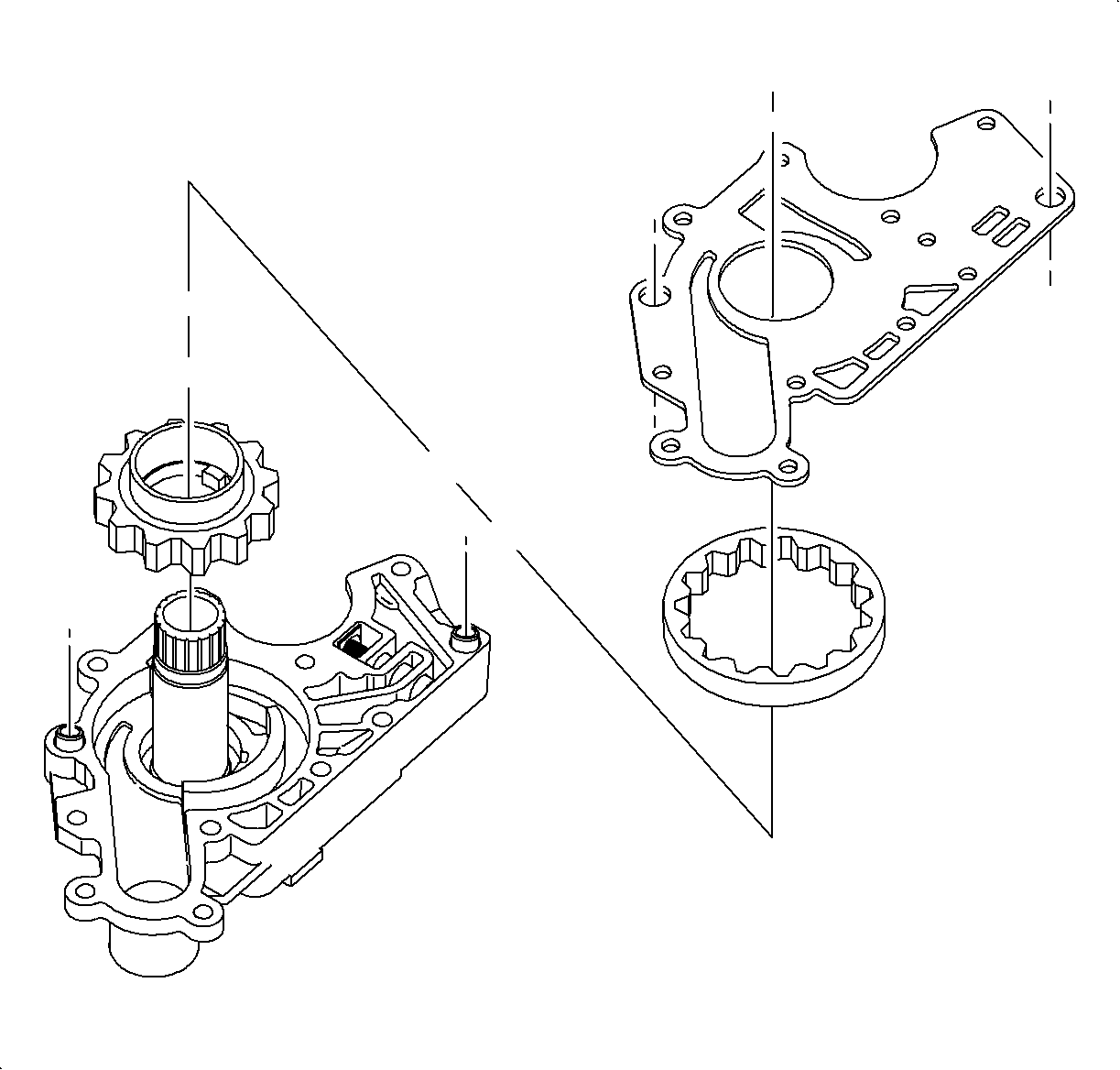
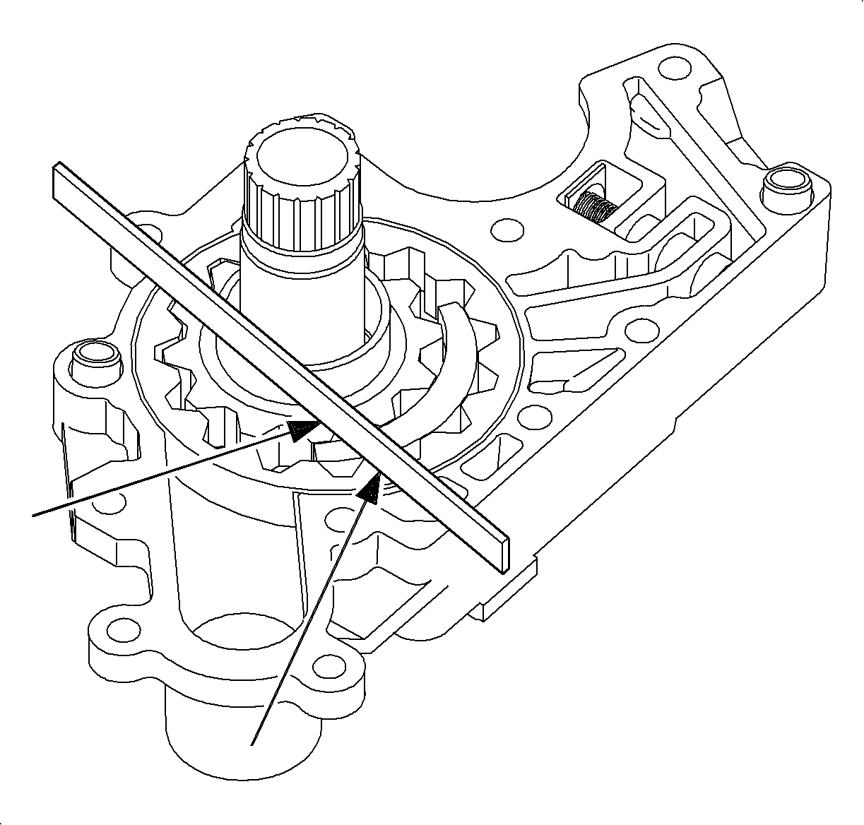
Clearance
| • | Drive gear clearance standard 0.012-0.041 mm (0.0004-0.0016 in). |
| • | Driven gear clearance standard 0.012-0.041 mm (0.0004-0.0016 in). |
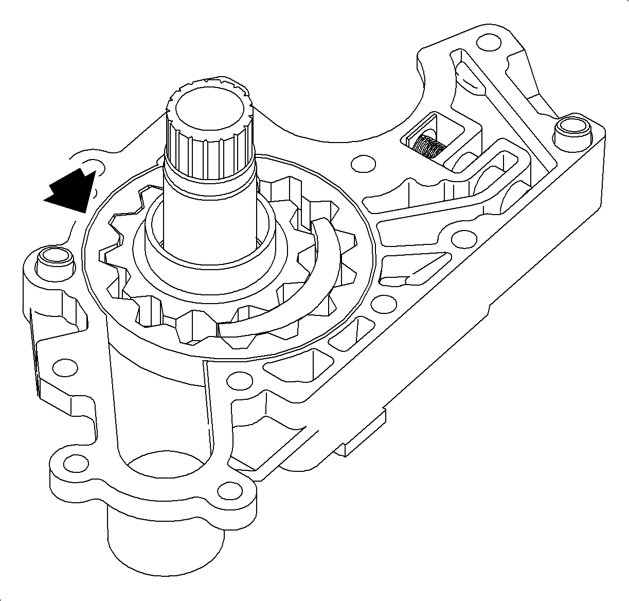
Clearance
Standard 0.064-0.139 mm (0.0025-0.0055 in).
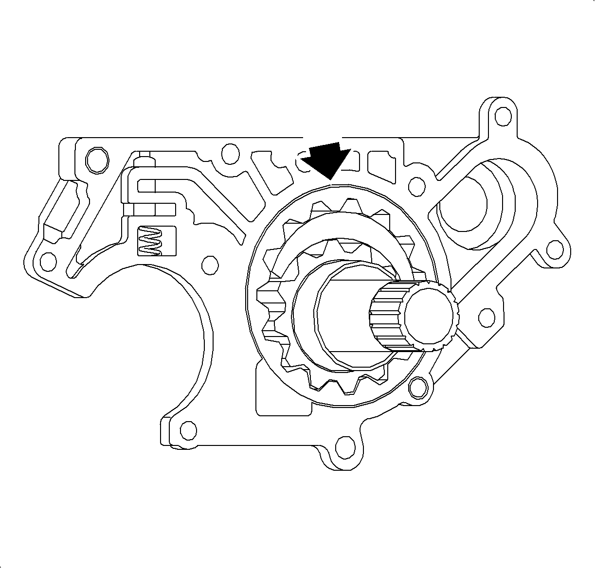
Clearance
Standard 0.191-0.341 mm (0.0075-0.0134 in)
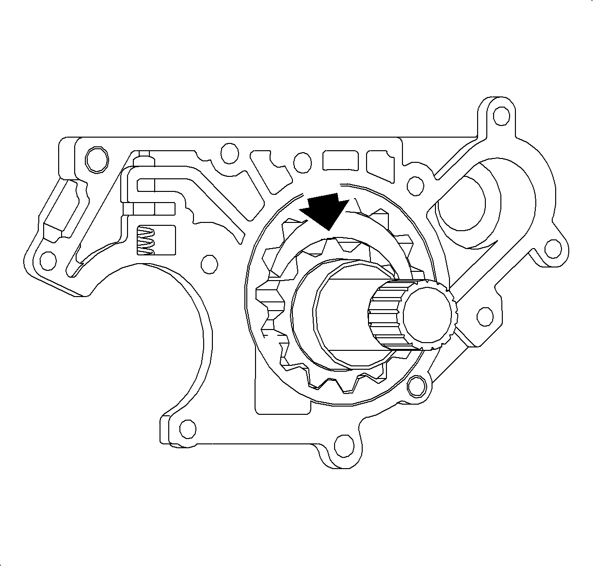
Clearance
Standard 0.128-0.278 mm (0.0050-0.0109 in)
