- Remove the output shaft bearing form the case. Refer to Case procedure in this service manual.
- Install the output shaft bearing on the shaft.
- Install the 1st driven gear and sprag clutch assembly.
- Install the 1st driven gear thrust washer.
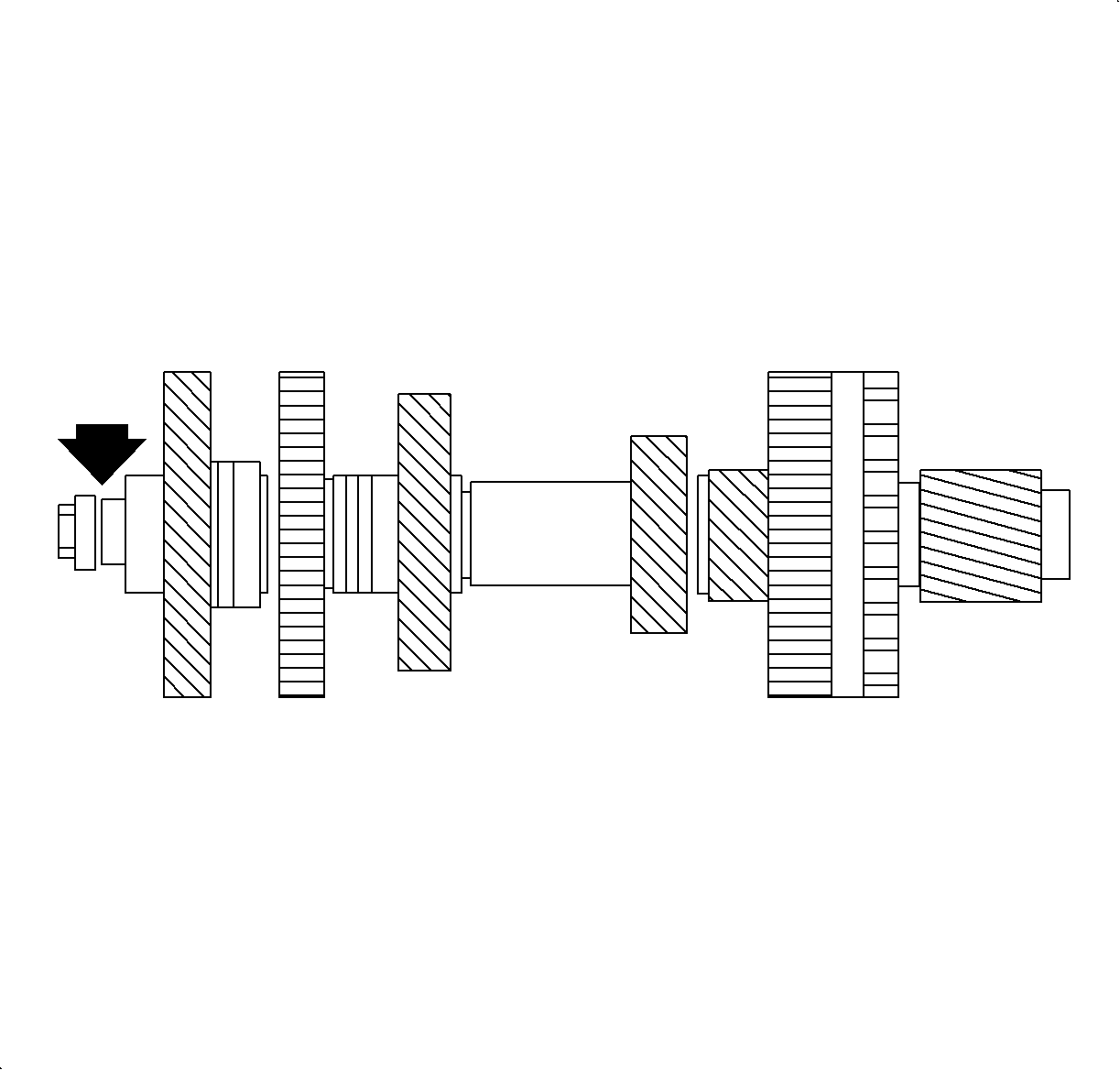
- Assemble the output shaft. Use the old nut and tighten.
- Measure the clearance between the 4th driven gear and the 3/4 thrust bearing. Make sure it spins and check the maximum clearance.
- Measure the clearance between the 2nd driven gear and the dog clutch hub.
- Measure the clearance between the reverse driven gear and the reverse driven gear thrust washer.
- Measure the clearance between the 1st driven gear washer and the 1st riven gear.
- Remove the output shaft clamp nut, 1st driven gear thrust washer, 1st driven gear and sprag assembly and output shaft bearing.
- Install the input shaft, output shaft, and differential. Grasp the input and output shafts and mesh gears. Have and assistant mesh the differential ring to the output shaft. Lower three components at the same time. Apply petroleum jelly on the output shaft bearing to aid in installation.
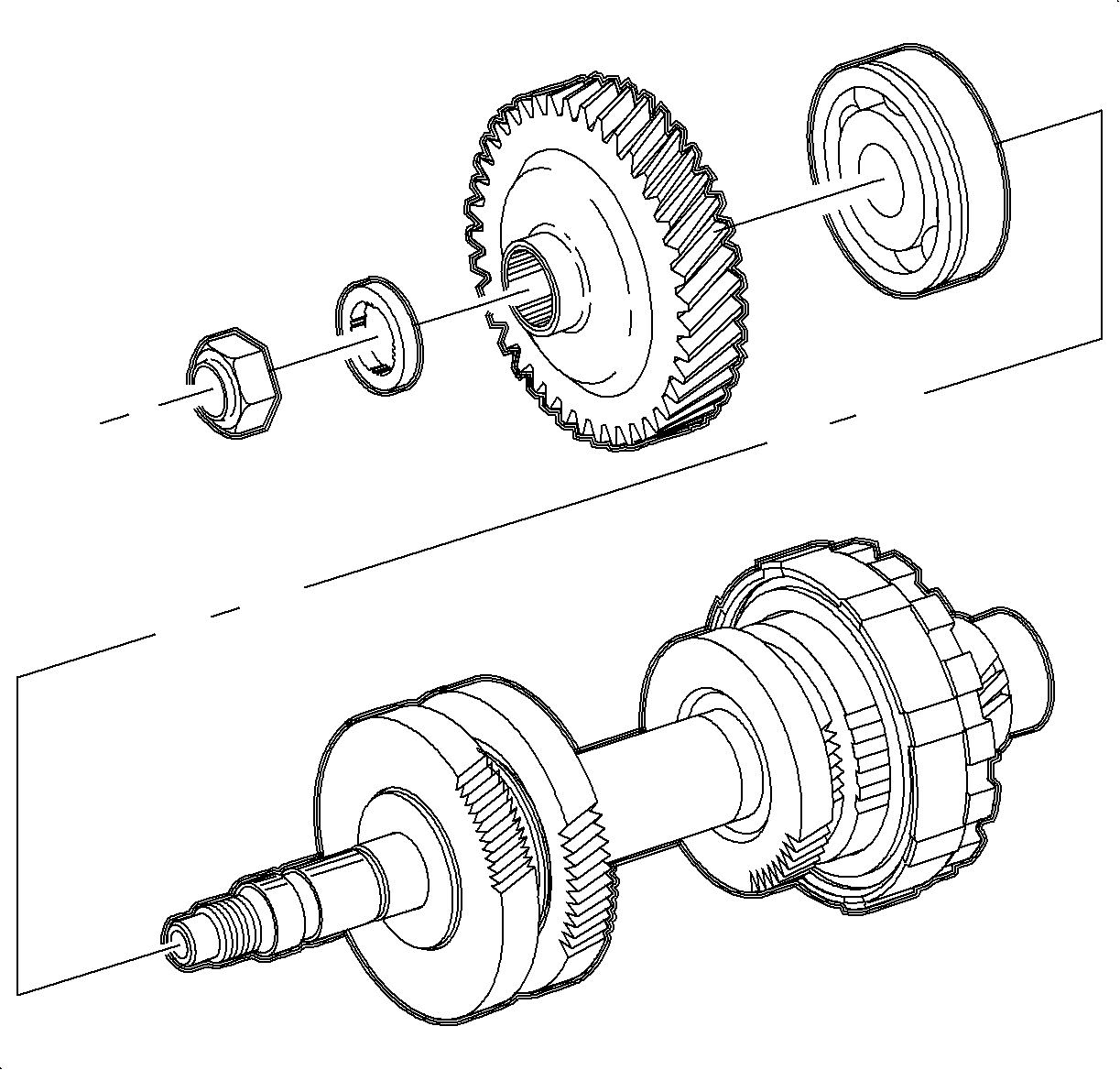
Important: To aid in holding output shaft, install the shaft into the converter housing and engage park pawl.
Tighten
Tighten the output shaft clamp nut to 150 N·m (111 lb ft).
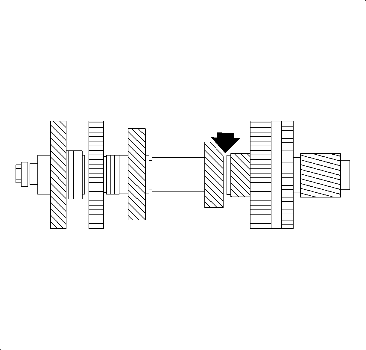
Clearance
| • | Clearance 0.464 mm (0.018 in) max. |
| • | Minimum -- the gear must rotate freely on the shaft. |
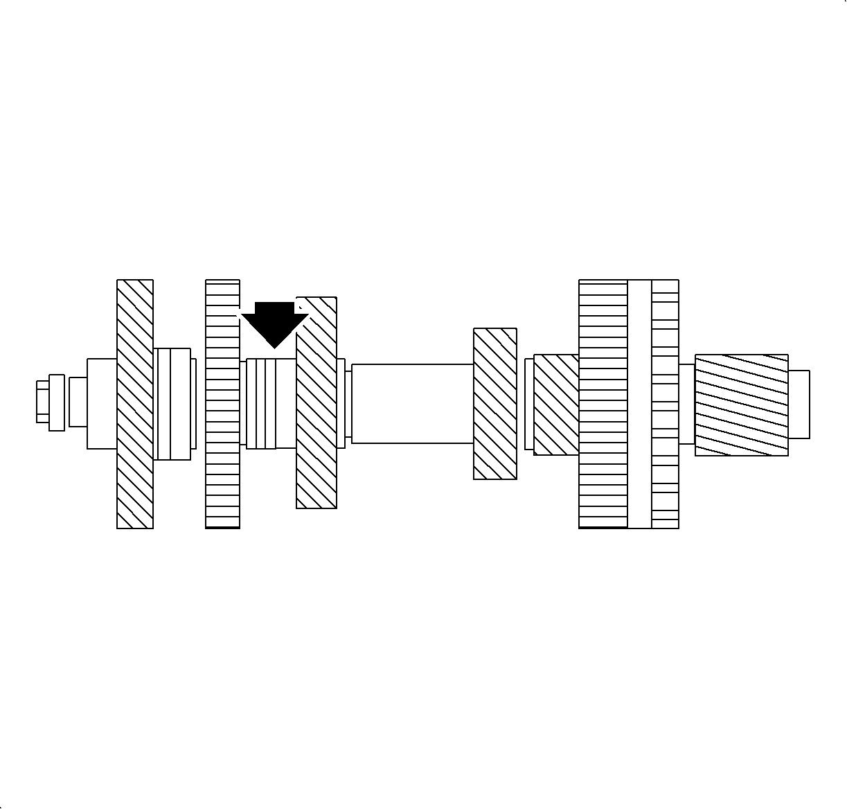
Important: Move the dog clutch sleeve as necessary to gain access for measurements.
Clearance
Standard 0.050-0.150 mm (0.002-0.006 in)
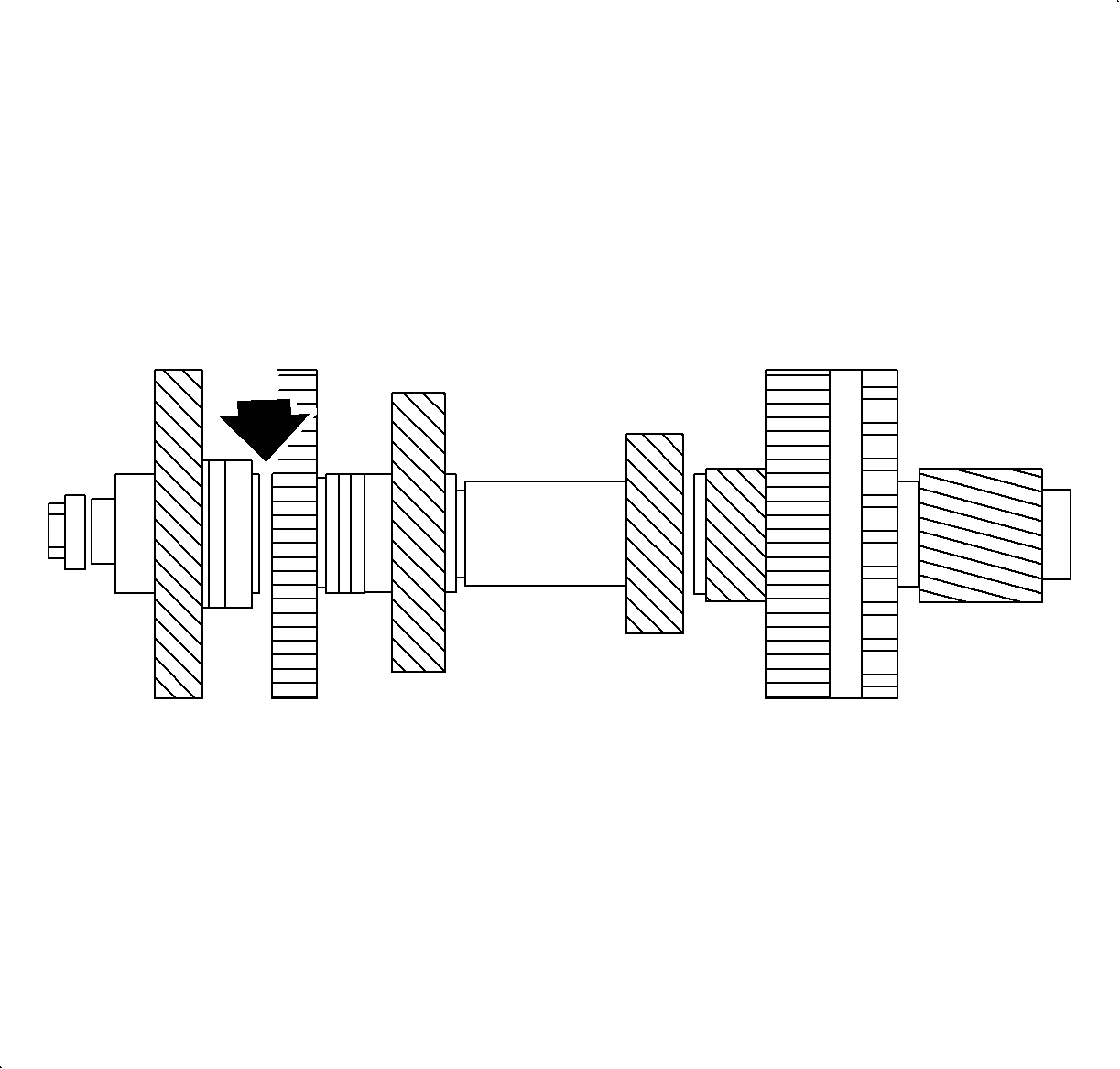
Clearance
| • | Standard 0.066-0.172 mm (0.003-0.007 in) |
| • | Minimum -- the gear must rotate freely on the shaft. |
Clearance
Standard 0.100-0.400 mm (0.004-0.016 in)

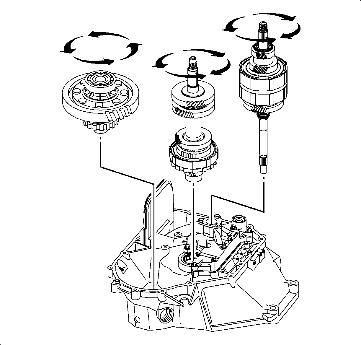
Notice: Input shaft, output shaft, and differential must be installed at same time or damage will result to output shaft roller bearing inner race. Bearing failure will result.
Important: If the stator shaft needle bearing assembly and input shaft to convertor O-ring were not installed during the input shaft assembly, make sure to lubricate and install the stator shaft needle bearing assembly on the input shaft or in the stator shaft prior to installing the shafts into the convertor housing.
