There are 5 inputs the PCM uses that influence TCC lockup, shift timing, shift feel and gear position. These include the input speed sensor (ISS), output speed sensor (OSS), stop lamp switch, transaxle fluid temperature (TFT) sensor and transaxle range switch.
Input Speed Sensor (ISS)
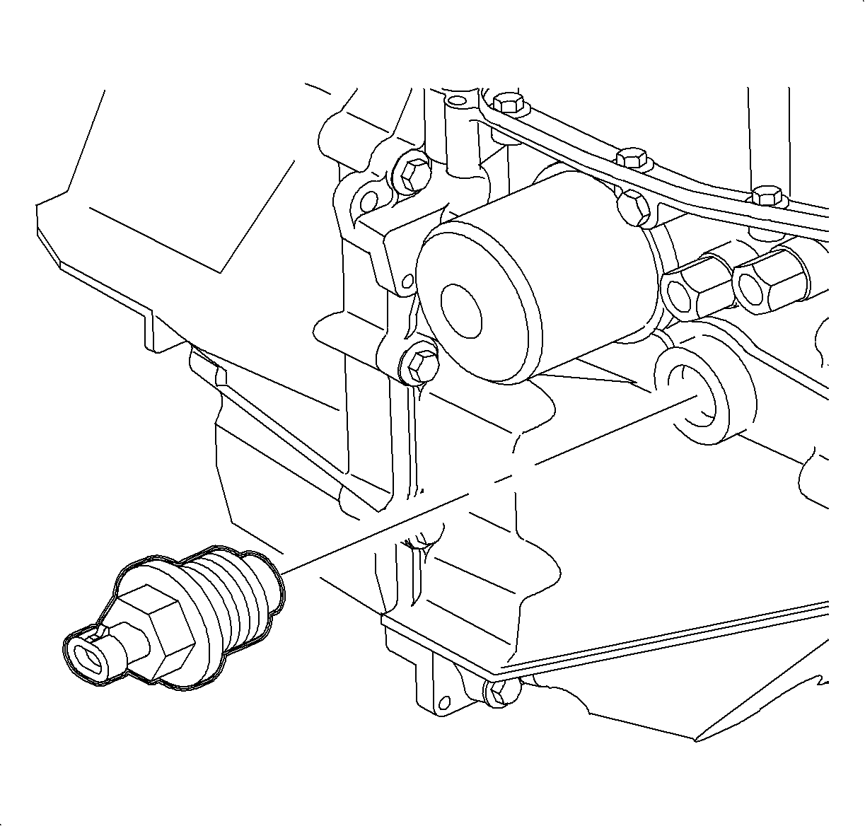
The input speed sensor (ISS) is threaded into the transaxle case located near the transaxle fluid filter. The ISS produces an AC voltage of different amplitude and frequency depending on the velocity of the input shaft. The ISS uses 8 total machined notches off the 2nd gear clutch to produce different AC voltage signals. This ISS signal is sent to the PCM, which is used to determine the velocity of the input shaft. A readable input occurs when the input shaft speed is greater than 250 RPM.
The PCM uses the ISS to monitor the speed of the input shaft. In conjunction with the crankshaft position (CKP) sensor, the PCM can determine the slip across the torque converter. In conjunction with the output speed sensor (OSS), the PCM can determine the slip across the commanded gear clutch pack. The PCM can use this information to determine the torque converter slippage, clutch gear slippage, actual gear ratio or lack of main line hydraulic pressure.
Output Speed Sensor (OSS)
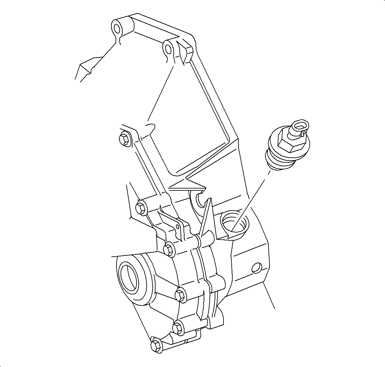
The output speed sensor (OSS) produces an AC voltage of different amplitude and frequency depending on the velocity of the output shaft. The OSS produces the signal from 16 evenly spaced machined notches on the transaxle differential carrier. The OSS produces a readable AC voltage signal when vehicle speed is above 5 km/h (3 mph). This OSS signal is sent to the PCM, which is used to determine the velocity of the output shaft.
The PCM uses the OSS to monitor the speed of the output shaft. In conjunction with the ISS, the PCM can determine the slip across the commanded gear clutch pack. The PCM can use this information to determine the actual gear ratio, gear slippage or lack of main line hydraulic pressure.
Stop Lamp Switch
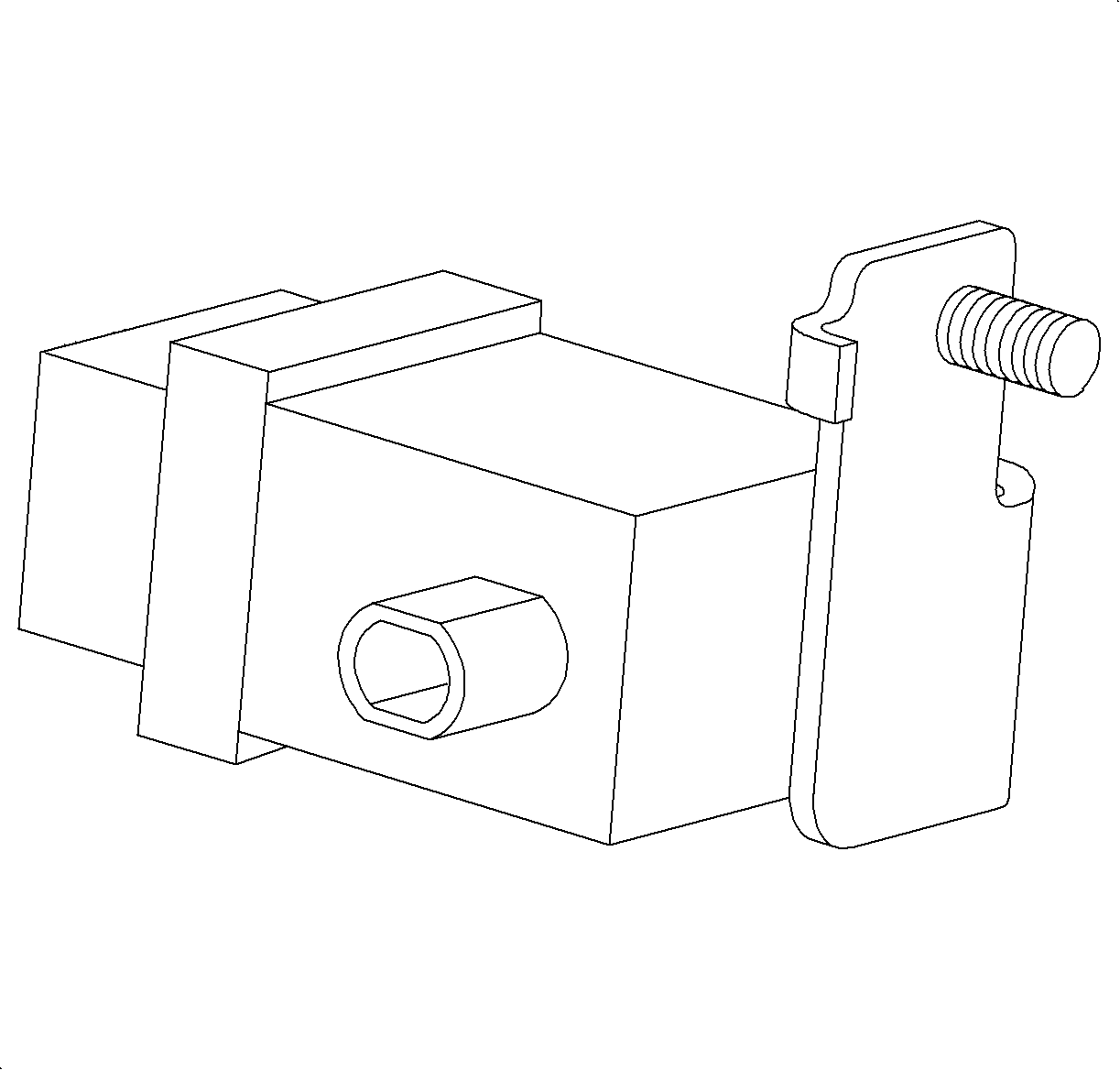
The stoplamp switch is a normally closed switch that allows battery voltage to be present at the PCM whenever the brake pedal is released. If the brake pedal is applied, the voltage at the PCM goes low indicating the pedal is being depressed. The PCM uses the brake input to determine TCC lockup and shift timing under different driving conditions. For example, if the transaxle is in 2nd gear and the engine speed is low with the brake pedal depressed, the PCM will unlock the torque converter. The stoplamp switch can also aid in determining if a downshift should occur while going down a hill.
Transaxle Fluid Temperature (TFT) Sensor
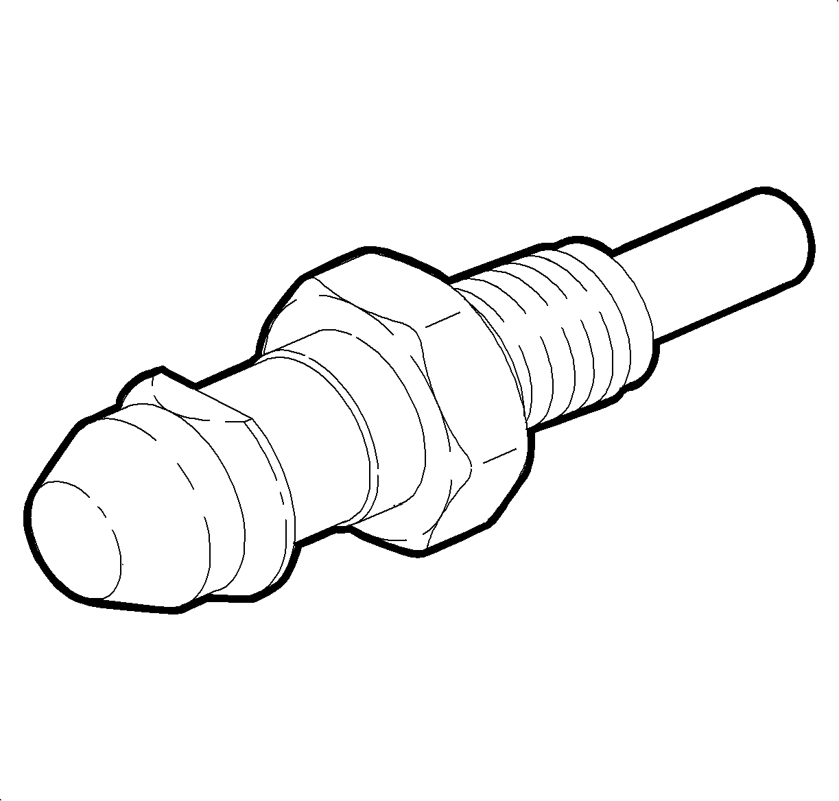
The transaxle fluid temperature (TFT) sensor is a thermistor that varies resistance according to changes in transaxle fluid temperature. The PCM supplies a five volt reference through a pull-up resistor to the sensor, which is connected to ground. When the sensor is cold it has high resistance (high signal voltage at PCM). As the sensor temperature increases, its resistance decreases (lower signal voltage at PCM). The PCM uses the signal voltage to determine transaxle fluid temperature.
The PCM uses transaxle fluid temperature to calculate enable/disable functions and shift feel. When the TFT sensor is below -13°C (9°F), the PCM will only command 1st and 3rd gears. Once this temperature is reached, the PCM will command normal shift scheduling.
The PCM also uses the TFT sensor input to enable TCC operation. The PCM will only allow TCC operation above 10-20°C (50-68°F) based on the intake air temperature (IAT) sensor input.
When the TFT sensor input is above 25°C (77°F) the PCM will begin adapting 1st, 3rd and 4th gears. Above 40°C (104°F) the PCM will begin adapting 2nd gear. The PCM uses the TFT sensor input to disable all transaxle adaptive functions below 25°C (77°F) and above 140°C (284°F).
Transaxle Range Switch
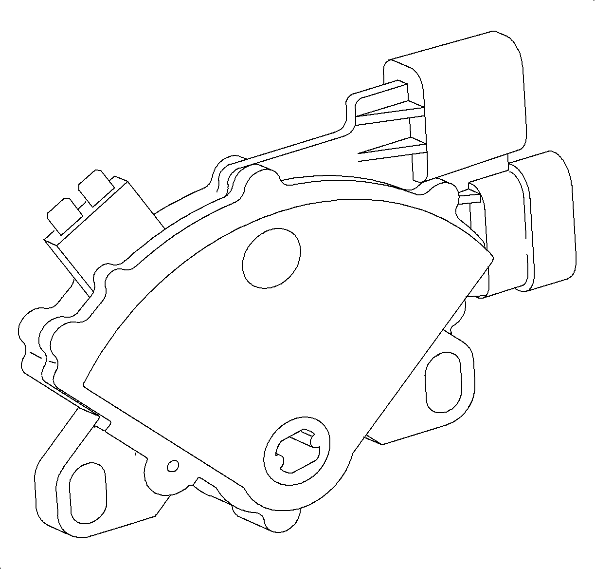
The transaxle range switch determines which gear position has been manually selected. The PCM determines this gear selection by detecting a combination of opens and grounds at the four switch (A, B, C and D) inputs of the transaxle range switch. When a switch is open, the PCM code input will be high (near ignition voltage). When the switch is closed, the PCM code input will be low (0 volts). The specific combinations of highs and lows (opens and grounds at switch) for the four code inputs at the PCM denote which gear position has been selected. Only one combination is possible for each manual gear selected. The PCM uses the gear selection to determine which gear to command On and how much main line pressure is needed to hold the gear being selected.
Transaxle Outputs
Solenoid Control Valve
There are five solenoids which have normally open valves. With no voltage applied to the terminals, a return spring holds the valve open and the solenoid allows oil to flow from the supply port to the control pressure port. When current is applied through the coil, the magnetic field is energized pulling the sliding armature against the return spring. When the armature is in this position, the valve is closed, the pressure supply port is blocked and the control port is connected to the exhaust port.
The solenoids are located in the transaxle valvebody and may be completely energized (closed), de-energized (open), or pulse width modulated (PWM). When a solenoid is being modulated, the valve opens and closes up to 70 times per second. This allows a percentage of the oil pressure available at the supply port to pass to the control port. The actual percentage is determined by an electrically controlled duty cycle from the powertrain control module (PCM). This is the ratio of the length of time the valve remains open (pulse width) to the total length of time of each cycle (one on and off cycle). These solenoids are the:
| • | Pressure Control (PC) Solenoid |
| • | Torque Converter Clutch (TCC) Solenoid |
| • | Shift Solenoid 2 |
| • | Shift Solenoid 3 |
| • | Shift Solenoid 4 |
Under normal transaxle operation, the PCM will only pulse width modulate the TCC and PC solenoids. The shift solenoids will be either On or Off.
