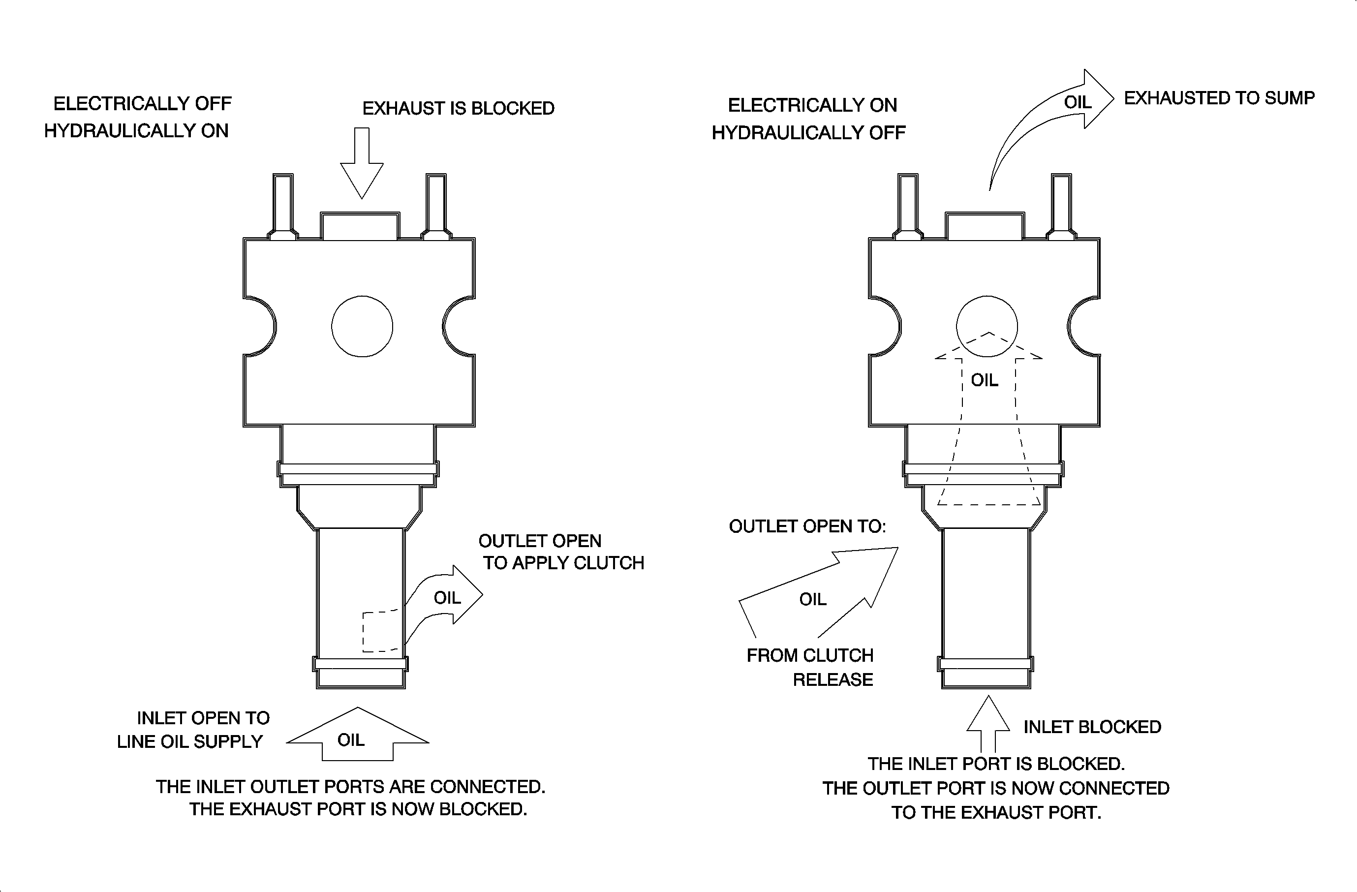
Solenoid Control Valve
The transaxle control solenoids are electrohydraulic solenoid valves consisting of a housing, valvebody, sliding armature and electromagnetic coil. They are a three port design with a pressure supply port, a pressure outlet or control pressure port, and an exhaust port.
The solenoids have normally open valves. When no voltage is applied to the terminals, a return spring holds the valve open and the solenoid will allow oil to flow from the supply port to the outlet pressure port. When current flows through the coil, the magnetic field is energized pulling the sliding armature against the return spring. When the armature is in this position, the valve is closed, the pressure supply port is blocked, and the control port is connected to the exhaust port.
The solenoids are located in the transaxle valvebody. A solenoid may be completely energized (closed), de-energized (open), or pulse width modulated (PWM). When it is being modulated, the valve opens and closes up to 70 times per second. This allows a percentage of the oil pressure available at the supply port to pass to the control port. The actual percentage is determined by an electrically controlled duty cycle from the PCM. This is the ratio of the length of time the valve remains open (pulse width) to the total length of time of each cycle, one ON and OFF cycle.
The five solenoids are the:
| • | The pressure control solenoid |
| • | The torque converter clutch (TCC) solenoid |
| • | The shift solenoid 2 |
| • | The shift solenoid 3 |
| • | The shift solenoid 4 |
Torque Converter Assembly
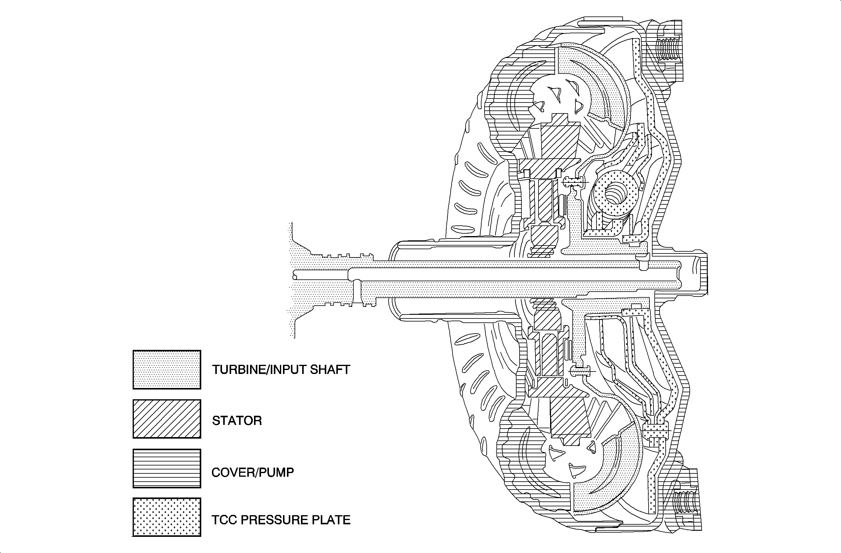
The torque converter assembly serves 3 primary functions. First, the torque converter is a fluid coupling that smoothly transmits engine torque to the transaxle gear train. This fluid coupling also allows the vehicle to stop without stalling the engine. Secondly, it multiplies torque from the engine to the transaxle for additional vehicle performance. Finally, the torque converter assembly provides a mechanical, for direct drive, link from the engine to the transaxle with the use of a torque converter clutch (TCC).
The torque converter assembly is a four element torque converter. It consists of a converter pump assembly, driving member, a turbine assembly, driven or output member, a clutch pressure plate assembly splined to the turbine to provide direct drive, and a stator assembly, reaction member. The converter cover is welded to the pump to seal all four members in a fluid filled housing.
The converter pump acts as a centrifugal pump, picking up fluid at its center and discharging this fluid at its rim between the blades. It is the force of this fluid from the pump hitting the turbine blades that causes the turbine to rotate. When the engine is idling in gear, the converter pump is not spinning fast and the force of the fluid leaving the pump is not great enough to turn the turbine and move the vehicle.
As engine speed increases, the fluid force increases and more engine power is transmitted to the gear train. Turbine speed does not reach engine speed until the torque converter clutch (pressure plate) is applied.
The pressure plate is splined to the turbine hub. It applies against the converter cover to provide a mechanical, direct drive, coupling of the engine to the transaxle. This mechanical coupling provides a more efficient transfer of engine torque to the drive wheels by eliminating the small amount of slippage that occurs in a fluid coupling. Thus, with the pressure plate (TCC) applied, the turbine assembly turns at engine speed.
To keep the pressure plate in the released position, TCC release fluid is fed through the turbine shaft in the release circuit. This release fluid then builds up pressure to counteract the converter clutch apply fluid and releases the pressure plate away from the cover. Fluid then leaves the converter by flowing between the turbine and stator shafts, and into the cooler and lubrication circuits.
In the apply position, converter clutch apply fluid flows between the stator shaft and converter hub to feed into the converter. This apply fluid fills the converter and applies the TCC pressure plate against the converter cover.
As the pressure plate applies, fluid between the converter cover and pressure plate is forced into the turbine shaft. The rate of exhausting TCC release fluid is controlled by the converter clutch solenoid to control the feel of the converter clutch. The fluid then flows back through the TCC release circuit.
To aid in controlling torsional shock during converter clutch apply, a damper assembly is incorporated in the converter clutch pressure plate. The spring loaded damper assembly is splined to the converter turbine assembly. The converter clutch pressure plate is attached to the pivoting mechanism of the damper assembly. This pivoting action allows the pressure plate to rotate independent of the damper assembly, up to approximately 18 degrees. The rate of independent rotation is controlled by the pivoting mechanism acting on the springs in the damper assembly. The cushioning effect of the damper assembly springs, aids in reducing converter clutch apply feel, and irregular torque pulses from the engine or road.
TCC Apply
| • | Engine temperature above 50°C (122°F). |
| • | Vehicle speed above 26 km/h (16 mph). |
| • | Transaxle fluid temperature above 20°C (68°F). |
TCC Release
| • | Low engine speed down shift, e.g., light throttle, or steady, throttle with load increase. |
| • | Low end of 3rd gear speed range, brake on = TCC OFF. |
| • | Fast deceleration, i.e., brake lock on ice = TCC OFF, gear = manual. |
Stator
The purpose of the stator is to redirect the flow of fluid returning from the turbine to assist the engine in turning the converter pump. This redirection increases the force of the fluid driving the turbine and, as a result, multiplies torque from the engine.
At low vehicle speeds, when greater torque is required, fluid from the turbine hits the front side of the stator blades, converter multiplying torque. Because the roller clutch holds the stator from moving in that direction, fluid is redirected to assist the engine in turning the converter pump. Fluid from the converter pump then has more force to turn the turbine assembly and multiply engine torque.
As vehicle speed increases, centrifugal force changes the direction of fluid from the turbine. The direction of this fluid is such that it hits the back side of the stator blades, converter at coupling speed. This causes the roller clutch to overrun and allow the stator to rotate freely, Fluid is no longer redirected and engine torque is not being multiplied.
Manual Valve
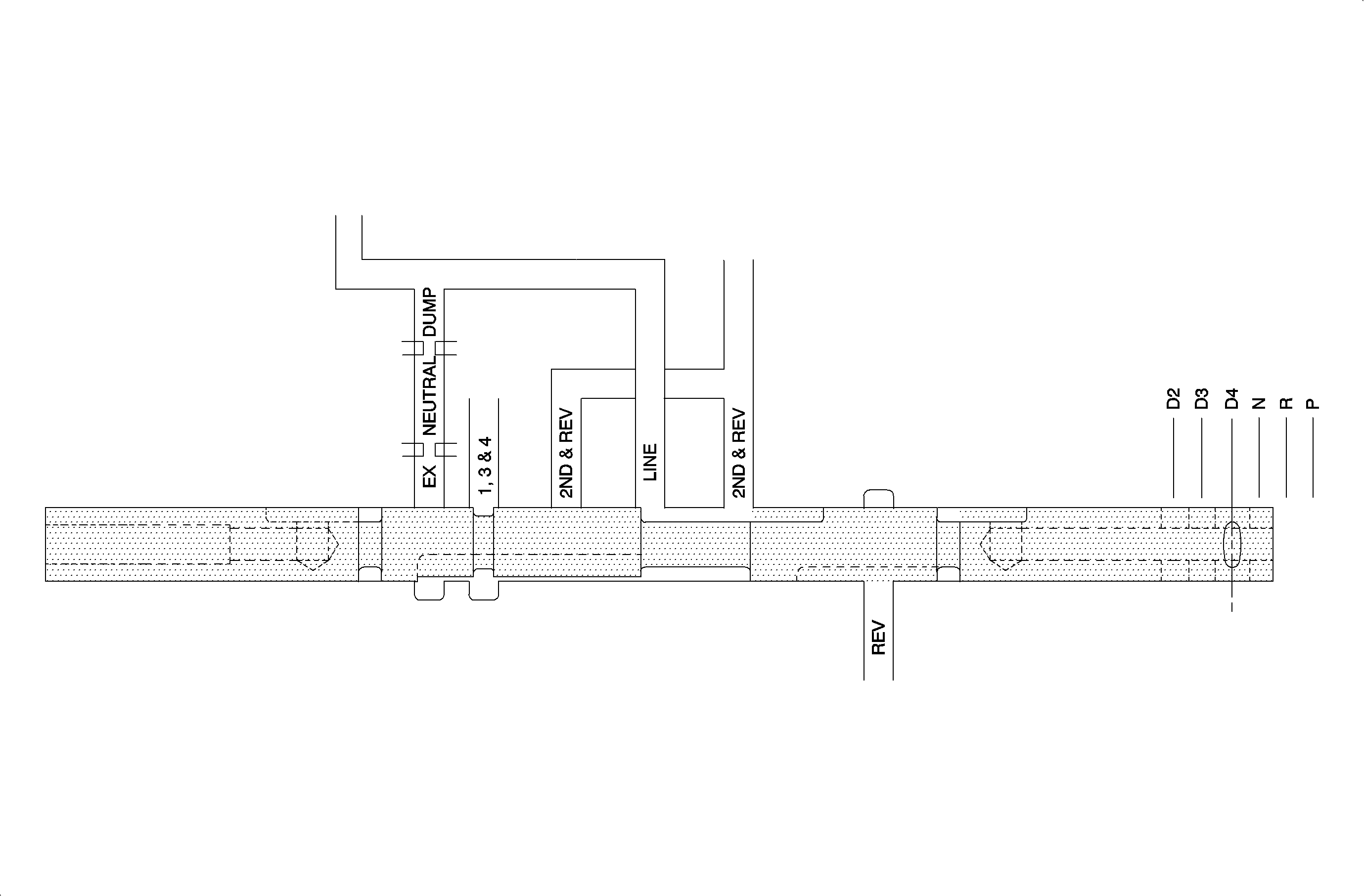
The manual valve controls oil routing to all clutches and solenoids in manual gear selections.
Park: The manual valve blocks line pressure from being routed to solenoids and 1st clutch. Solenoids and first clutch are exhausted. In park, lube pressure goes to maximum, controlled by the lube relief valve.Reverse: Line pressure is directed to the servo apply valve. All other circuits are exhausted.
Neutral: Pressure is exhausted out one end of the valve bore.
D4: Line pressure is directed to 1st, 2nd/reverse, and 3rd/4th supply circuits. Reverse is exhausted.
D3: Line pressure is directed to 1st, 2nd/reverse, and 3rd/4th supply circuits. Reverse is exhausted.
D2: Line pressure is directed to 1st, 2nd/reverse, and 3rd/4th supply circuits. Reverse is exhausted.
Clutch Priority Valve
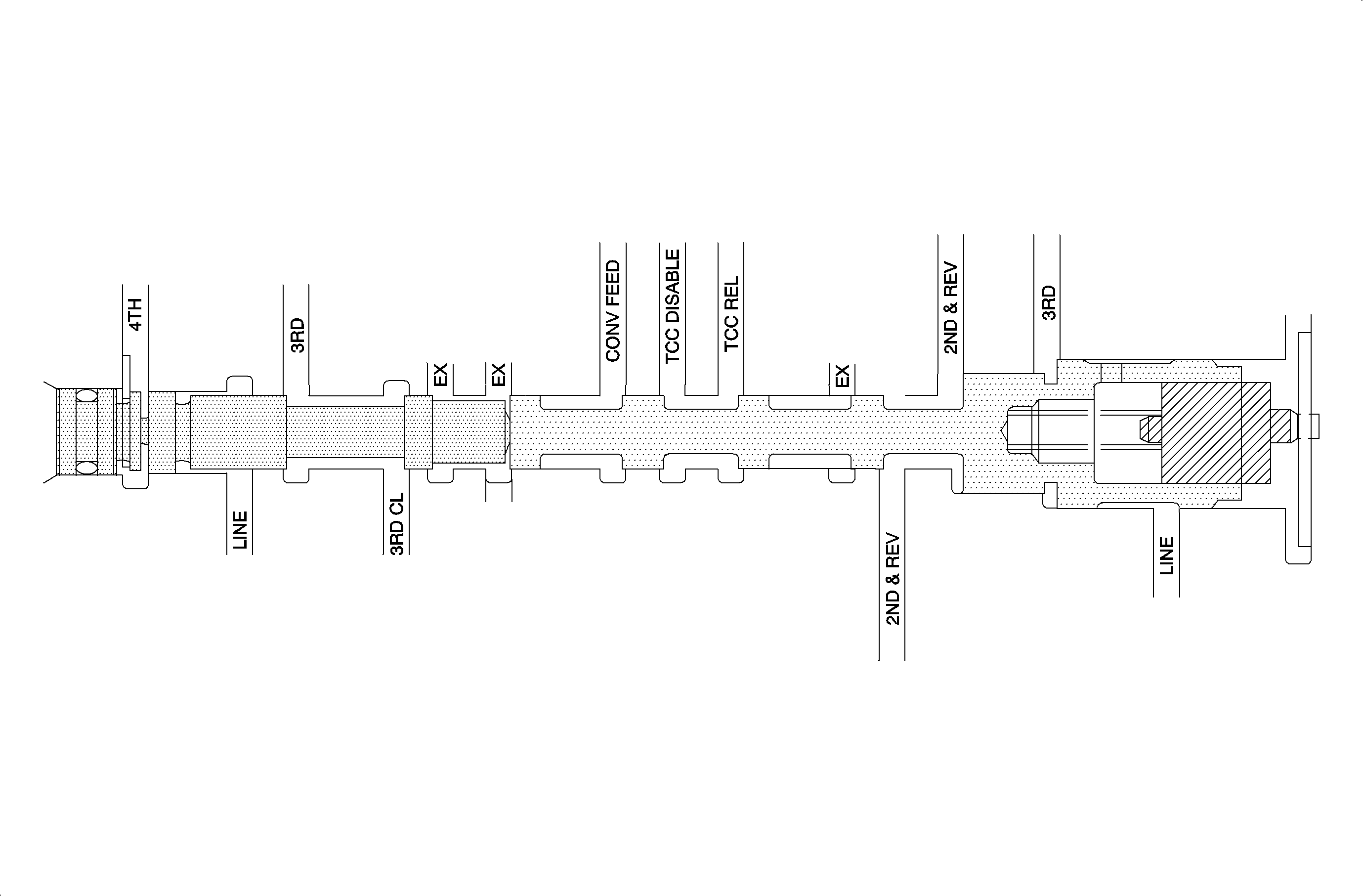
The clutch priority valve prevents 2 gears from being applied at the same time. Its main function is to provide a back-up system in the event of an electrical failure. If solenoid power is lost or battery voltage drops below 8 volts, the clutch priority valve and manual valve will provide reverse, and manual 4th.
During normal operation in 2nd, 3rd, and 4th, the clutch priority and 3rd clutch exhaust valves are held to the plug end of the 3rd exhaust valve by spring and line pressure. This position allows for normal operation of clutches by the solenoids.
2nd Gear Stuck ON: If the shift solenoid 2 electrical circuit fails, open, causing 2nd clutch to stay applied, the result will be a 2nd gear start. When a 2nd to 3rd shift is made, the combined pressure of 2nd and 3rd apply will act on the priority valve. The valve will move against the spring and line pressure. 2nd apply pressure will be blocked OFF, and 2nd clutch will be exhausted. When the transaxle shifts to 4th, the 3rd clutch pressure is exhausted at the 3rd actuator and 2nd will remain exhausted as 4th clutch pressure is applied to the end of the 3rd clutch exhaust valve.3rd Gear Stuck ON: If the shift solenoid 3 electrical circuit fails, open, causing 3rd clutch to stay applied, the result will be a 3rd gear start. When 2nd gear is attempted, 2nd clutch will be exhausted as 2nd and 3rd apply pressures are applied to the clutch priority valve at the same time. When vehicle speed reaches the point for a shift to 4th, 4th apply pressure is applied to the 3rd clutch exhaust valve which will cause it to move against line pressure toward the clutch priority valve. 3rd apply pressure is blocked and 3rd clutch is exhausted.
TCC Disable: Any time the priority valve moves toward the plunger and a clutch is exhausted, TCC is disabled. Converter feed, TCC apply, oil is valved to TCC disable causing equal pressure on both sides of the torque converter clutch which results in clutch release.
Hydraulic Back-up: During low battery voltage conditions the PCM will shut down, opening all solenoids electrically, ON hydraulically. During system failures back-up is provided by the manual valve supplying 2nd apply oil in D2 and 3rd/4th oil in D3 and D4. At the same time that line pressure begins to act against spring pressure, line pressure control from the pressure control solenoid is applied to the line pressure control plunger to increase force on the regulator valve in the same direction as the spring. Line pressure is increased as pressure to the pressure control plunger is increased by the pressure control solenoid.
Pressure Regulator Valve
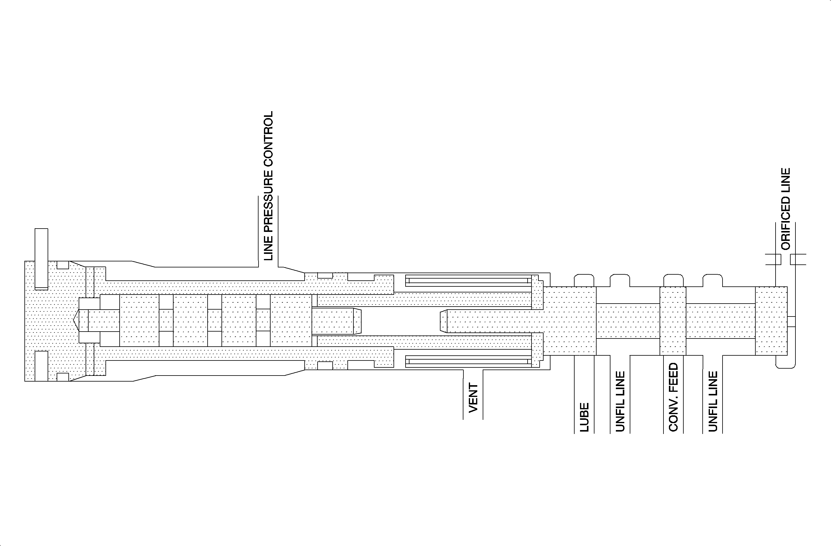
The pressure regulator valve controls line pressure to provide the correct pressure to apply clutches, supply lube and converter feed. The valve exhausts line pressure to the lube or converter feed circuit to reduce line pressure to a required operating pressure. If operating conditions require a higher pressure, as in high load, the regulator will exhaust less and line pressure will increase.
The pressure regulator contains the pressure regulator valve, line pressure control plunger, and pressure regulator spring which are the main components that control line pressure.
On initial start up the pressure regulator is bottomed in the bore by spring and line pressure control pressure. At this time no pressure is being exhausted until orificed line pressure increases enough to cause the regulator valve to move against spring pressure. As the regulator valve moves against spring pressure, line pressure is exhausted to lube and converter feed to control pressure.
At the same time that line pressure begins to act against spring pressure, line pressure control from the pressure control solenoid is applied to the line pressure control plunger. This increases force on the regulator valve in the same direction as the spring. Line pressure is increased as pressure to the pressure control plunger is increased by the pressure control solenoid.
When engine RPM is raised and lowered, the regulator valve and control plunger float back and forth against spring pressure and line pressure control as a single unit. As RPM begins to rise, pump output increases. The resulting line pressure increase acting on the pressure regulator valve forces the valve against spring and line pressure control to the point where line pressure is exhausted. Line pressure drops and the spring and line pressure control force the valve back, blocking off exhaust. During normal operation the valve continually maintains line pressure by moving back and forth to exhaust.
Servo Apply Valve
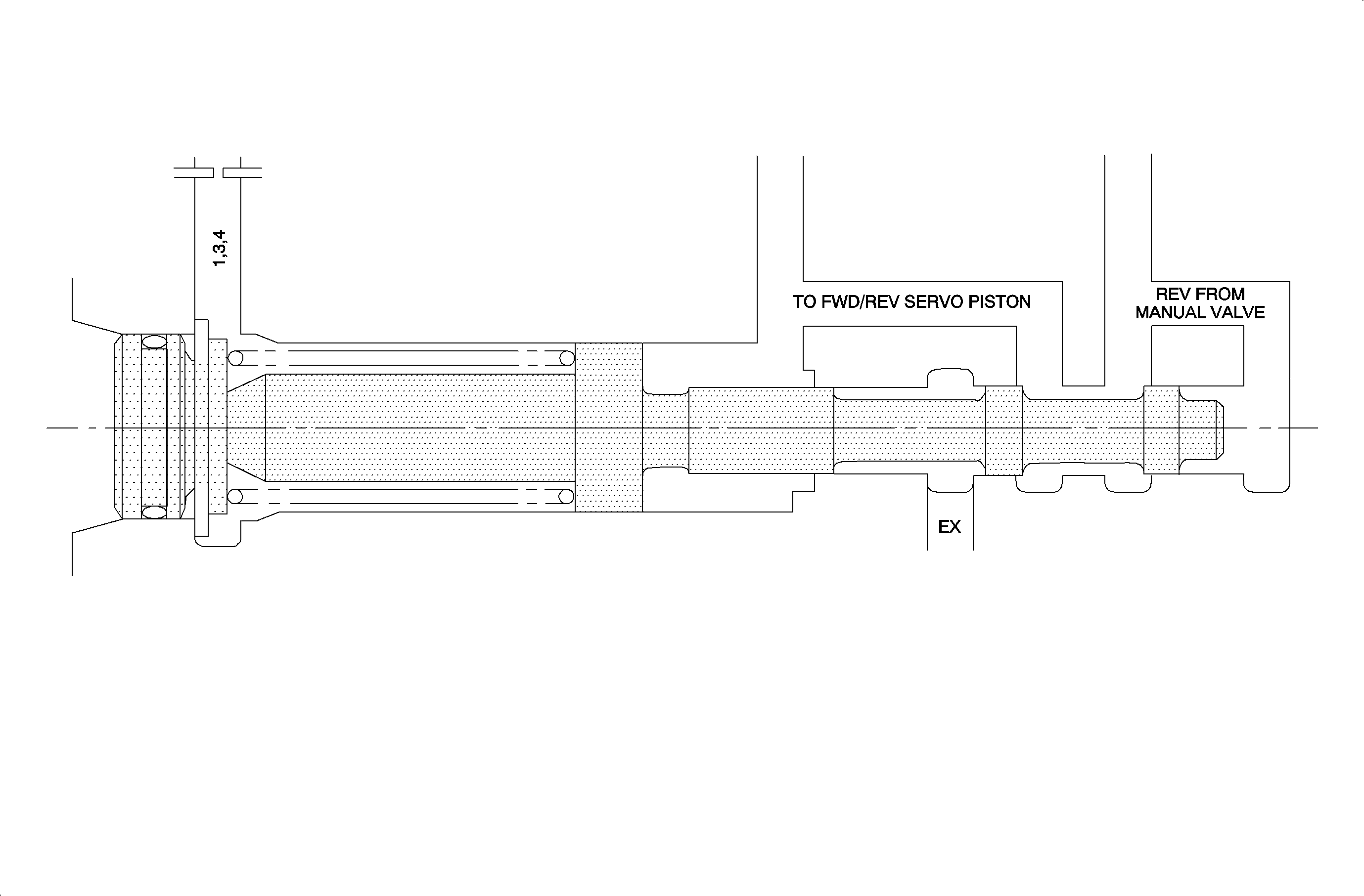
The servo apply valve, located in the valvebody, is used to control reverse apply oil to the forward/reverse servo piston. When reverse is selected, the manual valve will allow oil to be applied to the servo apply valve. If vehicle speed input to the PCM indicates the vehicle is less than 8 km/h (5 mph) then the dog clutch can be moved to the reverse direction without causing damage. With the vehicle speed less than 8 km/h (5 mph), and reverse selected, the PCM will command high-line pressure. When high-line pressure is commanded, the pressure will move the servo apply valve against the spring which opens up the passage allowing oil to pass through the servo apply valve to the forward/reverse servo piston.
If reverse is selected when vehicle speed is greater than 8 km (5 mph), the PCM will command low-line pressure causing the servo apply spring to keep the passage in the servo apply valve closed, preventing oil to reach the forward/reverse servo piston. This action does not allow the dog clutch to move, thus preventing internal damage to the transaxle.
Converter Limiting Valve
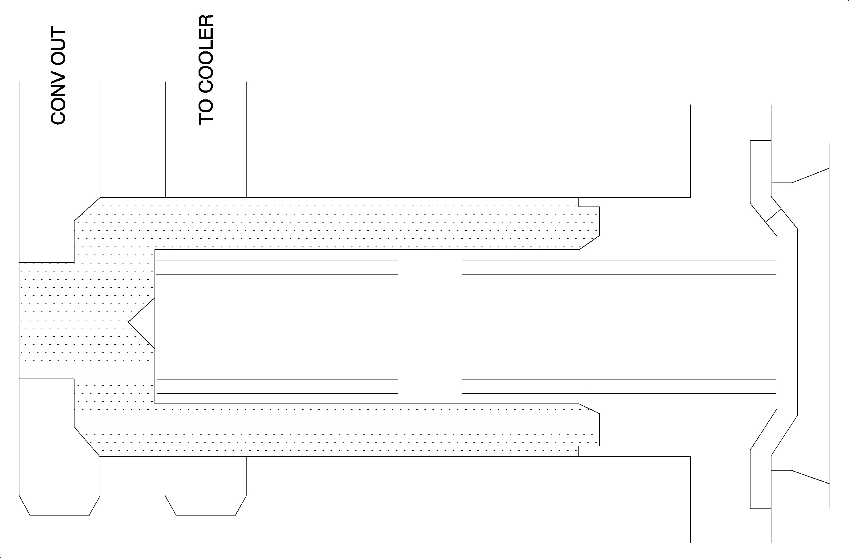
The converter limiting valve exhausts oil to keep the converter pressure in a normal operating range. Excess pressure is exhausted through the transaxle oil cooler to sump.
Converter Charge Valve
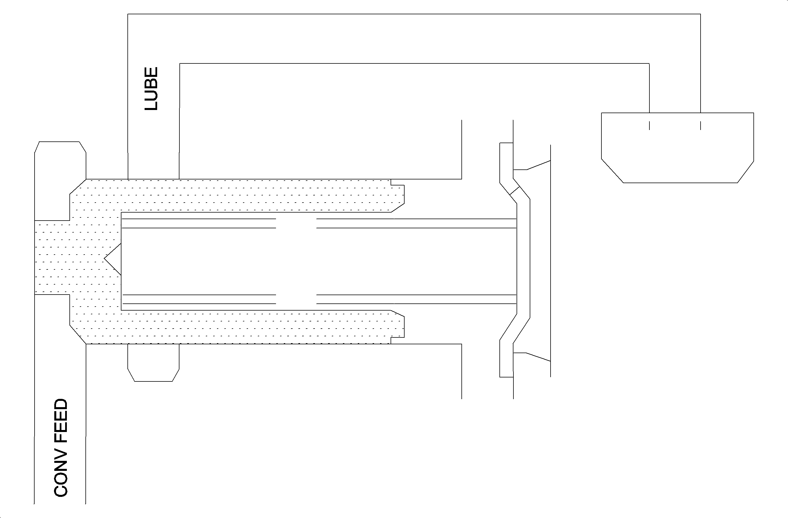
The converter charge valve limits converter feed pressure to prevent torque converter damage from over-pressure. During cold operation the converter limiting valve can not exhaust enough oil to keep converter pressure in a normal operating range. When converter feed pressure goes above normal operating pressure, the valve will unseat and dump excess oil pressure to the transaxle sump.
Lube Relief Valve
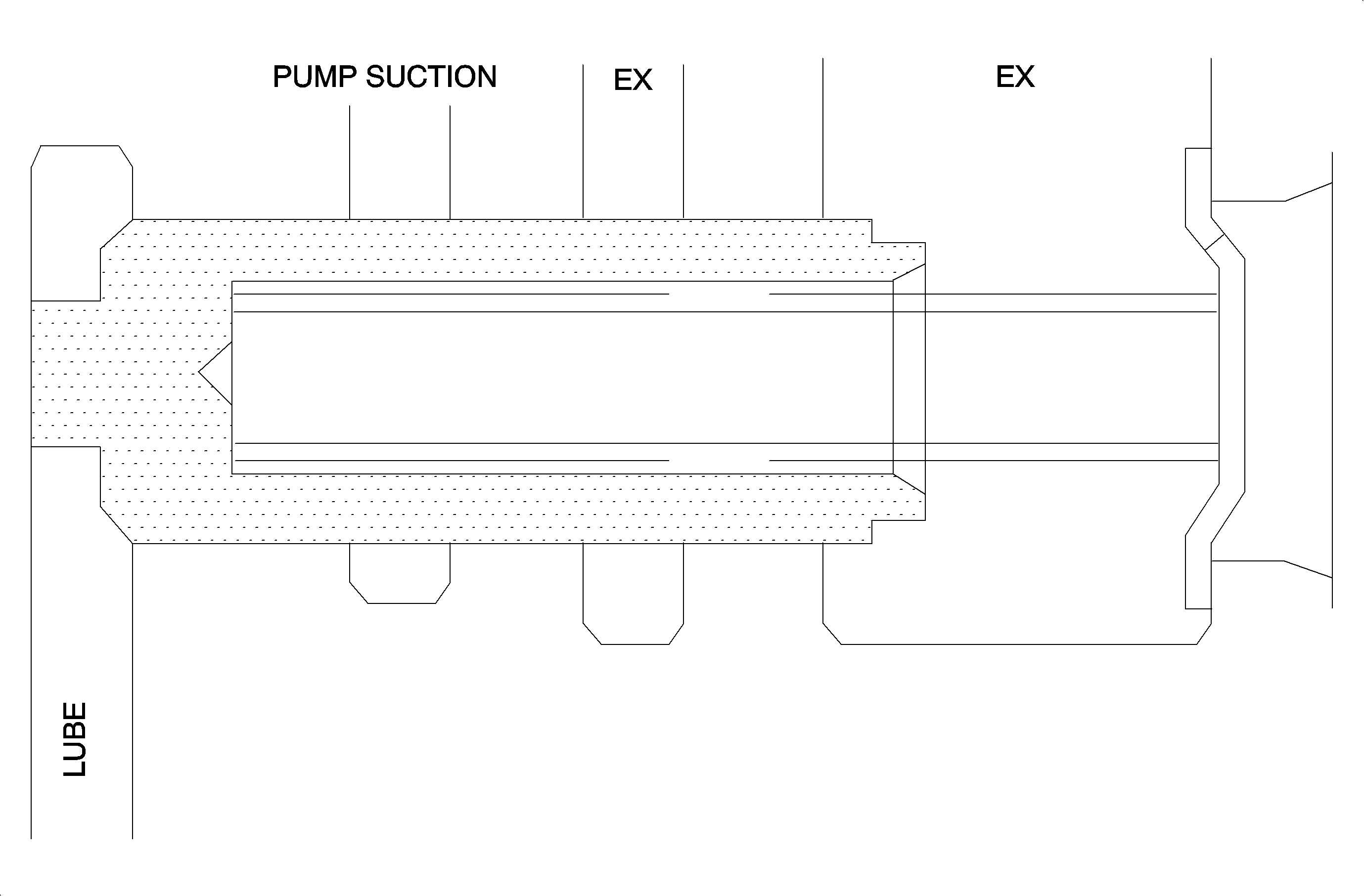
The lube relief valve is located in the pump and exhausts excess lube pressure to the suction side of the pump.
