For 1990-2009 cars only
Tools Required
| • | J 44015 Steering Linkage Installer |
| • | SA91100C Tie Rod Separator |
| • | SA9140E Torque Angle Gage |
Removal Procedure
- Raise vehicle on hoist.
- Remove wheel and tire.
- Remove tie rod end-to-knuckle nut and discard.
- Loosen tie rod lock nut.
- Using SA91100C (or equivalent), separate outer tie rod from steering knuckle.
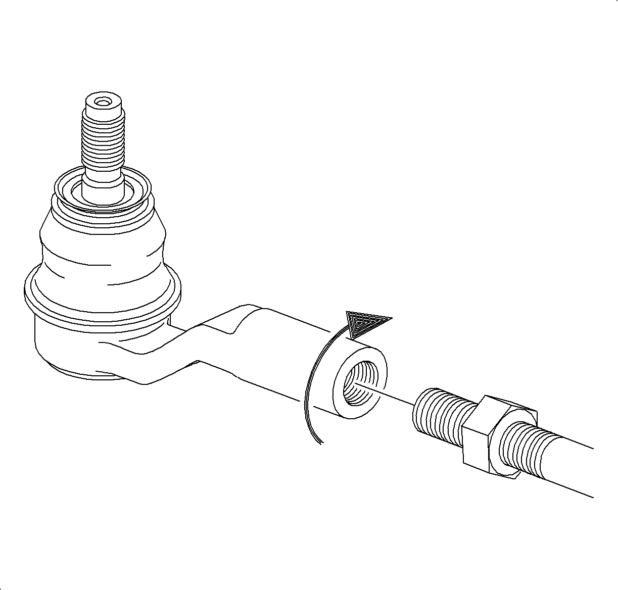
- Unthread outer tie rod from inner tie rod and remove from vehicle.
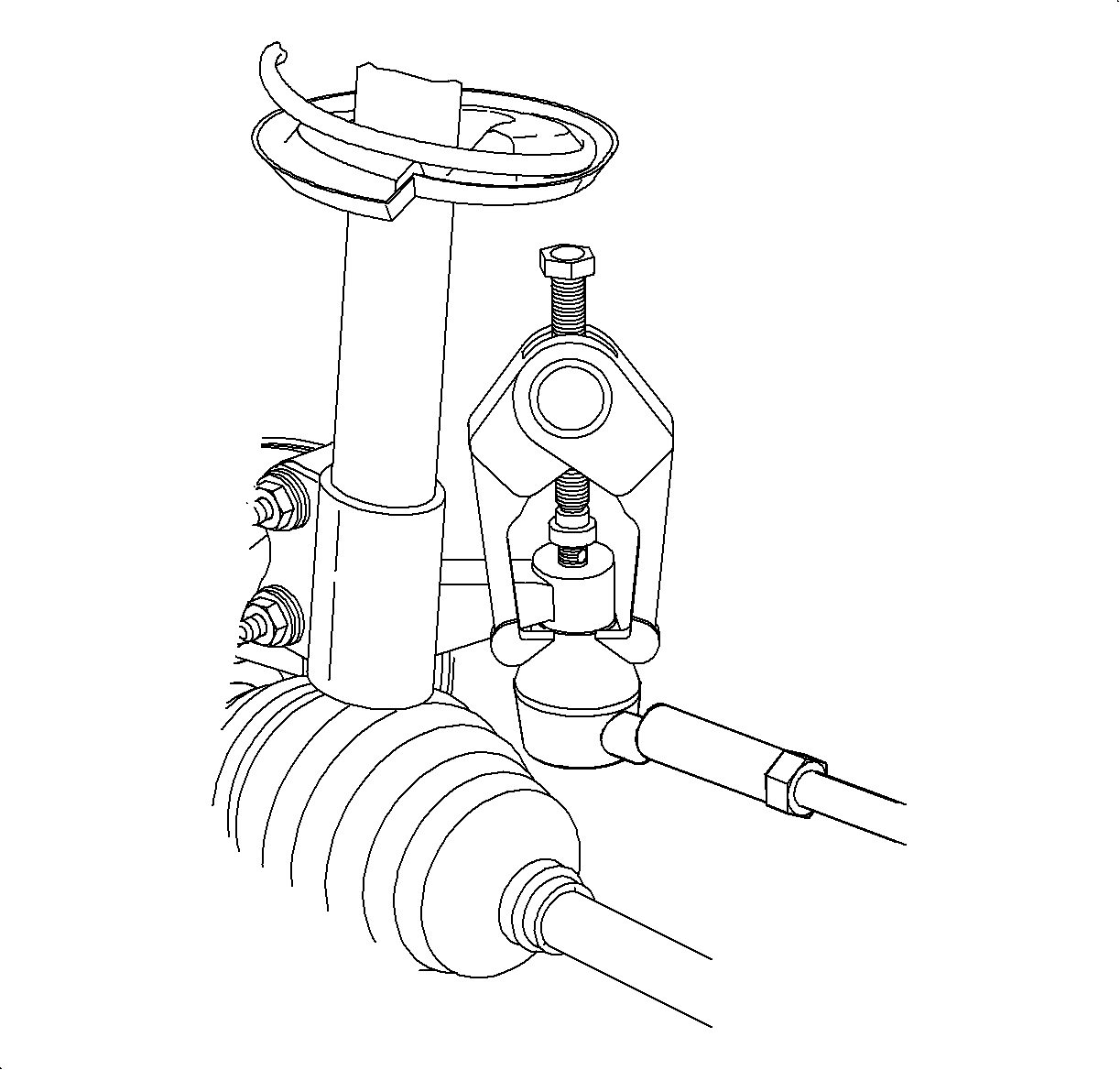
Notice: Do not attempt to separate the joint using a wedge-type tool because seal may be damaged.
Installation Procedure
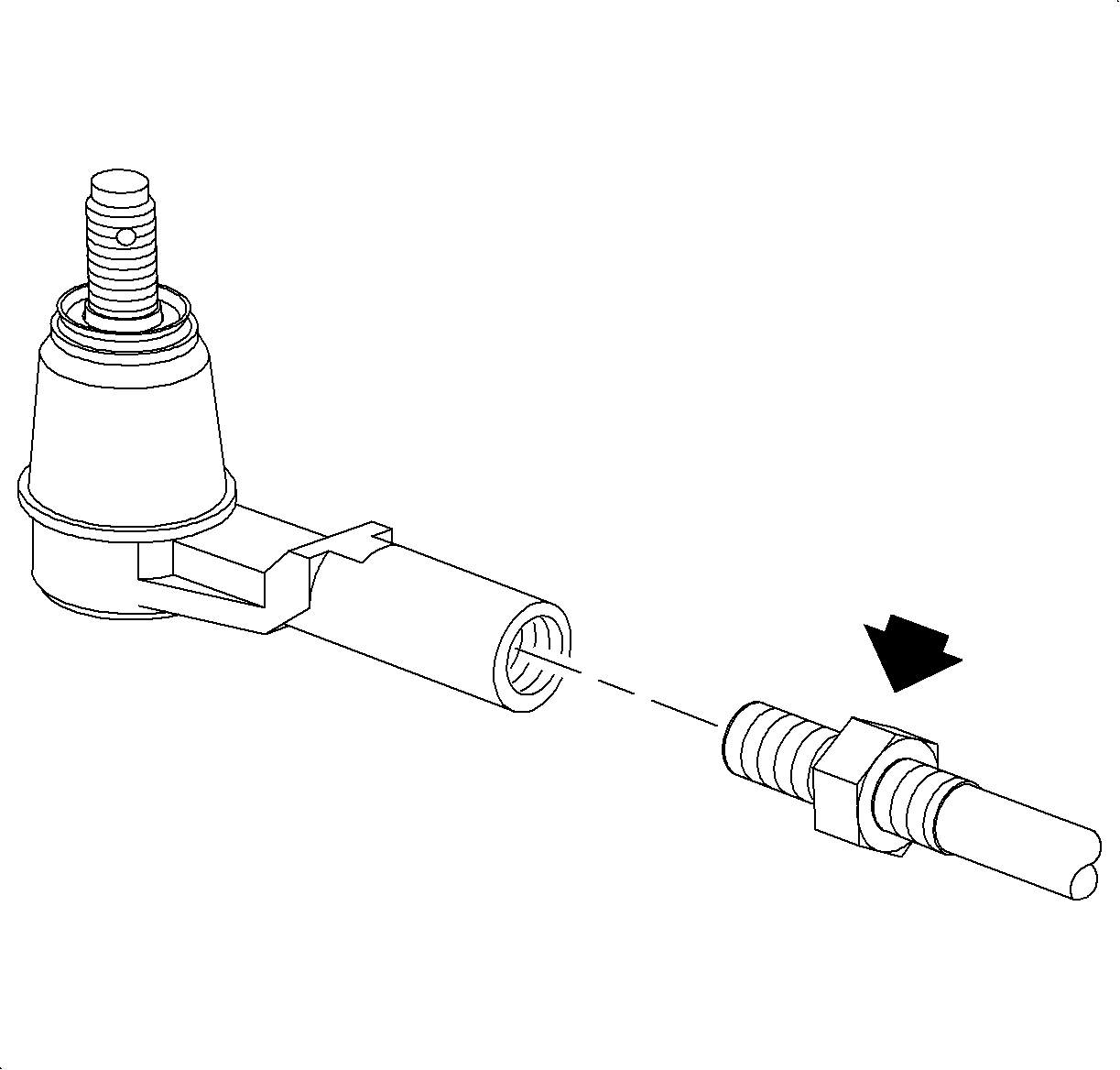
- Thread outer tie rod onto inner tie rod.
- Seat tie rod end into steering knuckle by using J 44015 or equivalent.
- Remove linkage installer and install new tie rod end nut.
- Hand tighten tie rod lock nut.
- Position wheel onto hub.
- Install wheel nuts and tighten in a crisscross pattern. Repeat tightening pattern to make sure torque is correct.
- Set toe. Refer to Wheel Alignment Specifications in Wheel Alignment.

Important: Tie rod end threads must be thoroughly cleaned before tightening nut. Do not lubricate any portion of the stud.
Important: Use new nut, torque retention of old nut may not be sufficient.
Tighten
Tighten Tie Rod Linkage Installer 45 N·m (33 lbs ft).
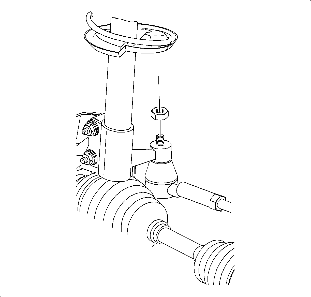
Important: This procedure requiresSA9140E (or equivalent).
Tighten
Tighten Tie Rod-to-Steering Knuckle Nut 25 N·m (19 lbs ft)
+134°.
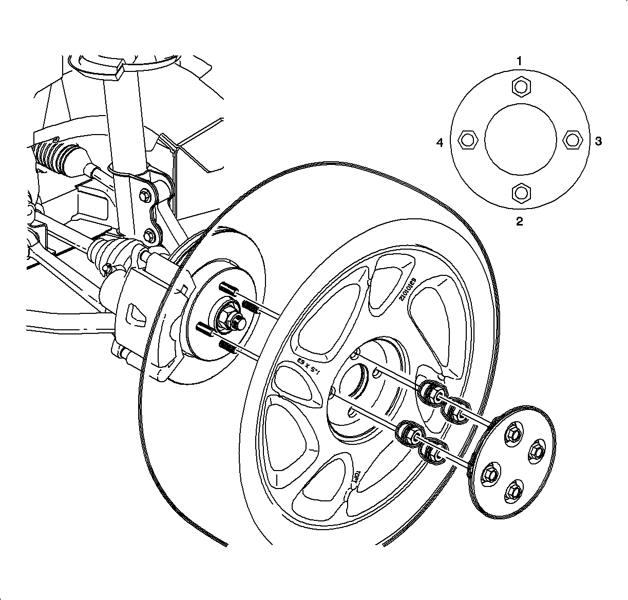
Notice: Before installing wheels, remove rust or corrosion from wheel mounting surfaces and brake rotors/drums. Failure to do so can cause wheel nuts to loosen in service.
Tighten
Tighten Wheel Nuts 140 N·m (103 lbs ft).
